2001 NISSAN ALMERA N16 fuel filter
[x] Cancel search: fuel filterPage 816 of 2493
Fuel Filter
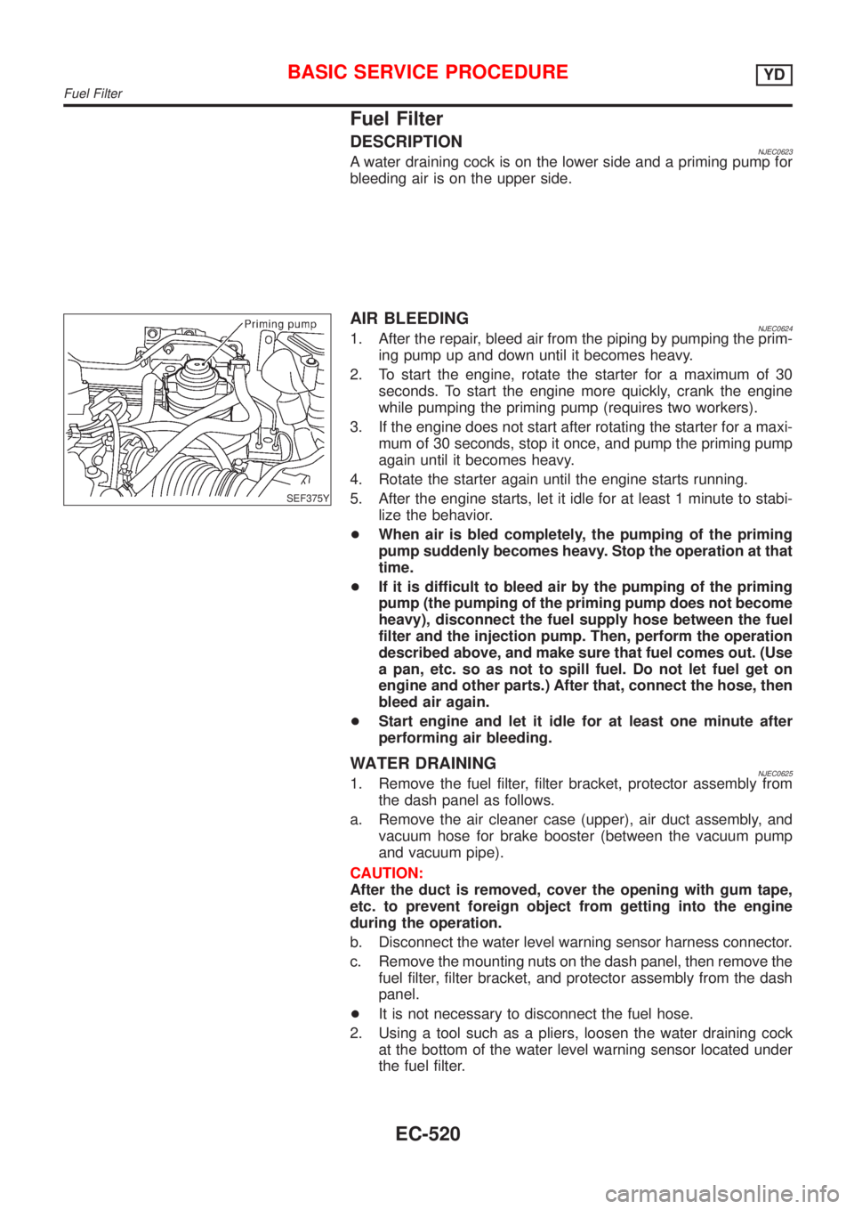
DESCRIPTIONNJEC0623A water draining cock is on the lower side and a priming pump for
bleeding air is on the upper side.
SEF375Y
AIR BLEEDINGNJEC06241. After the repair, bleed air from the piping by pumping the prim-
ing pump up and down until it becomes heavy.
2. To start the engine, rotate the starter for a maximum of 30
seconds. To start the engine more quickly, crank the engine
while pumping the priming pump (requires two workers).
3. If the engine does not start after rotating the starter for a maxi-
mum of 30 seconds, stop it once, and pump the priming pump
again until it becomes heavy.
4. Rotate the starter again until the engine starts running.
5. After the engine starts, let it idle for at least 1 minute to stabi-
lize the behavior.
+When air is bled completely, the pumping of the priming
pump suddenly becomes heavy. Stop the operation at that
time.
+If it is difficult to bleed air by the pumping of the priming
pump (the pumping of the priming pump does not become
heavy), disconnect the fuel supply hose between the fuel
filter and the injection pump. Then, perform the operation
described above, and make sure that fuel comes out. (Use
a pan, etc. so as not to spill fuel. Do not let fuel get on
engine and other parts.) After that, connect the hose, then
bleed air again.
+Start engine and let it idle for at least one minute after
performing air bleeding.
WATER DRAININGNJEC06251. Remove the fuel filter, filter bracket, protector assembly from
the dash panel as follows.
a. Remove the air cleaner case (upper), air duct assembly, and
vacuum hose for brake booster (between the vacuum pump
and vacuum pipe).
CAUTION:
After the duct is removed, cover the opening with gum tape,
etc. to prevent foreign object from getting into the engine
during the operation.
b. Disconnect the water level warning sensor harness connector.
c. Remove the mounting nuts on the dash panel, then remove the
fuel filter, filter bracket, and protector assembly from the dash
panel.
+It is not necessary to disconnect the fuel hose.
2. Using a tool such as a pliers, loosen the water draining cock
at the bottom of the water level warning sensor located under
the fuel filter.
BASIC SERVICE PROCEDUREYD
Fuel Filter
EC-520
Page 817 of 2493
3. Install the fuel filter, filter bracket, and protector assembly tem-
porarily. Then, drain the water by pumping the priming pump
with the filter standing straight.
+Extend the drain hose if necessary.
Water amount when the MI lights up:
65 - 100 m!(2.3 - 3.5 Imp fl oz)
CAUTION:
When the water is drained, the fuel is also drained. Use a pan,
etc. to avoid fuel adherence to the rubber parts such as the
engine mount insulator.
4. Tighten the water draining cock, then install the fuel filter, filter
bracket, protector assembly in the reverse order of removal.
CAUTION:
Do not over-tighten the water draining cock. This will damage
the cock thread, resulting in water or fuel leak.
5. Bleed air of the fuel filter. Refer to EC-520.
+Start engine and let it idle for at least one minute after
performing air bleeding.
BASIC SERVICE PROCEDUREYD
Fuel Filter (Cont'd)
EC-521
Page 819 of 2493
+Erasing the emission-related diagnostic information using CONSULT-II is easier and quicker than
switching the diagnostic test mode using the data link connector.
Malfunction Indicator (MI)
DESCRIPTIONNJEC0628
SAT652J
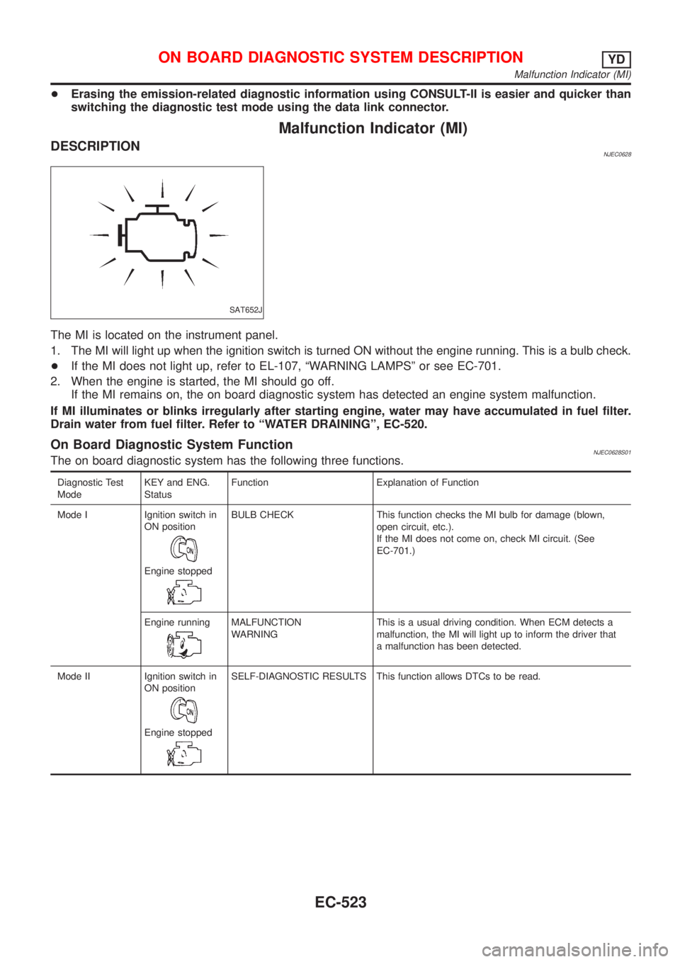
The MI is located on the instrument panel.
1. The MI will light up when the ignition switch is turned ON without the engine running. This is a bulb check.
+If the MI does not light up, refer to EL-107, ªWARNING LAMPSº or see EC-701.
2. When the engine is started, the MI should go off.
If the MI remains on, the on board diagnostic system has detected an engine system malfunction.
If MI illuminates or blinks irregularly after starting engine, water may have accumulated in fuel filter.
Drain water from fuel filter. Refer to ªWATER DRAININGº, EC-520.
On Board Diagnostic System FunctionNJEC0628S01The on board diagnostic system has the following three functions.
Diagnostic Test
ModeKEY and ENG.
StatusFunction Explanation of Function
Mode I Ignition switch in
ON position
Engine stopped
BULB CHECK This function checks the MI bulb for damage (blown,
open circuit, etc.).
If the MI does not come on, check MI circuit. (See
EC-701.)
Engine running
MALFUNCTION
WARNINGThis is a usual driving condition. When ECM detects a
malfunction, the MI will light up to inform the driver that
a malfunction has been detected.
Mode II Ignition switch in
ON position
Engine stopped
SELF-DIAGNOSTIC RESULTS This function allows DTCs to be read.
ON BOARD DIAGNOSTIC SYSTEM DESCRIPTIONYD
Malfunction Indicator (MI)
EC-523
Page 832 of 2493
Basic InspectionNJEC0632Precaution:
Perform Basic Inspection without electrical or mechanical
loads applied;
+Headlamp switch is OFF,
+On vehicles equipped with daytime light systems, set
lighting switch to the 1st position to light only small
lamps.
+Air conditioner switch is OFF,
+Rear defogger switch is OFF,
+Steering wheel is in the straight-ahead position, etc.
1 INSPECTION START
1. Check service records for any recent repairs that may indicate a related problem.
2. Check the current need for scheduled maintenance, especially for fuel filter and air cleaner filter. Refer to MA-4, ªPeri-
odic Maintenanceº.
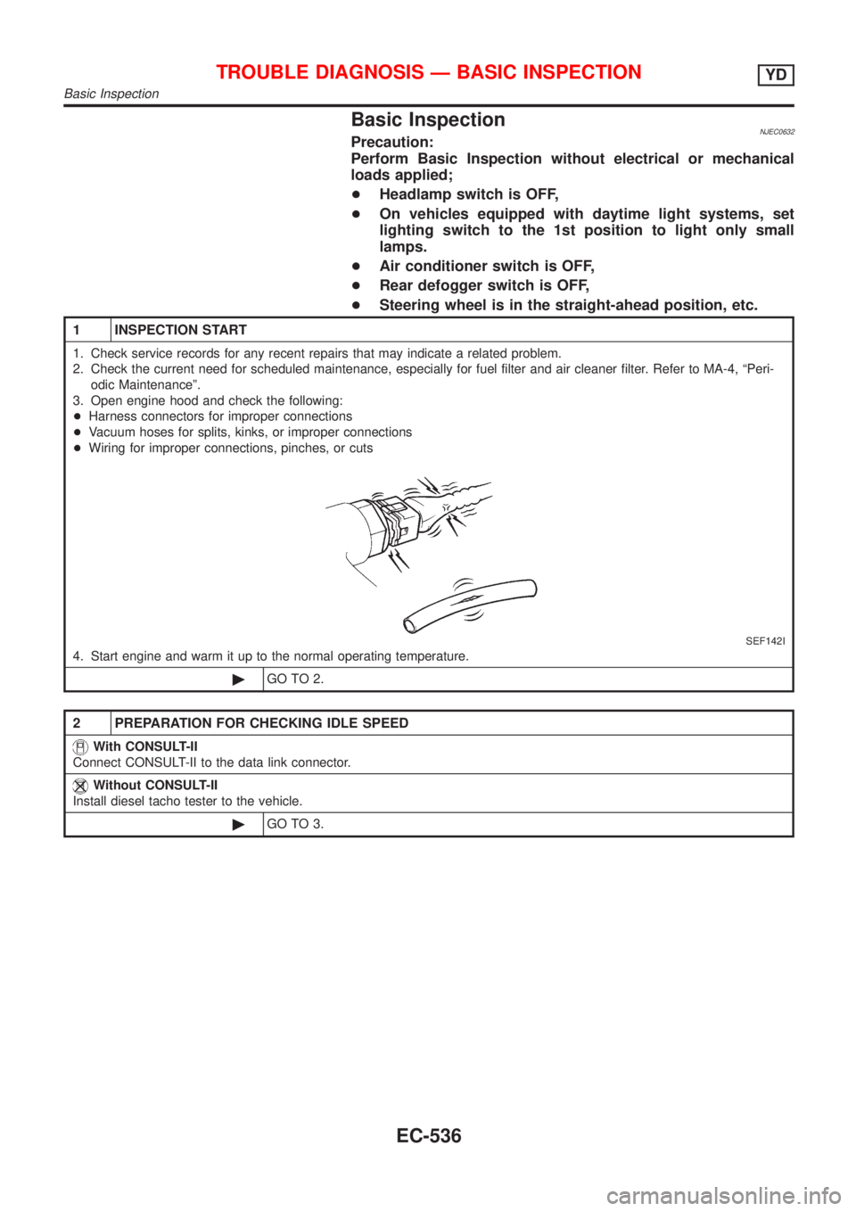
3. Open engine hood and check the following:
+Harness connectors for improper connections
+Vacuum hoses for splits, kinks, or improper connections
+Wiring for improper connections, pinches, or cuts
SEF142I
4. Start engine and warm it up to the normal operating temperature.
©GO TO 2.
2 PREPARATION FOR CHECKING IDLE SPEED
With CONSULT-II
Connect CONSULT-II to the data link connector.
Without CONSULT-II
Install diesel tacho tester to the vehicle.
©GO TO 3.
TROUBLE DIAGNOSIS Ð BASIC INSPECTIONYD
Basic Inspection
EC-536
Page 834 of 2493
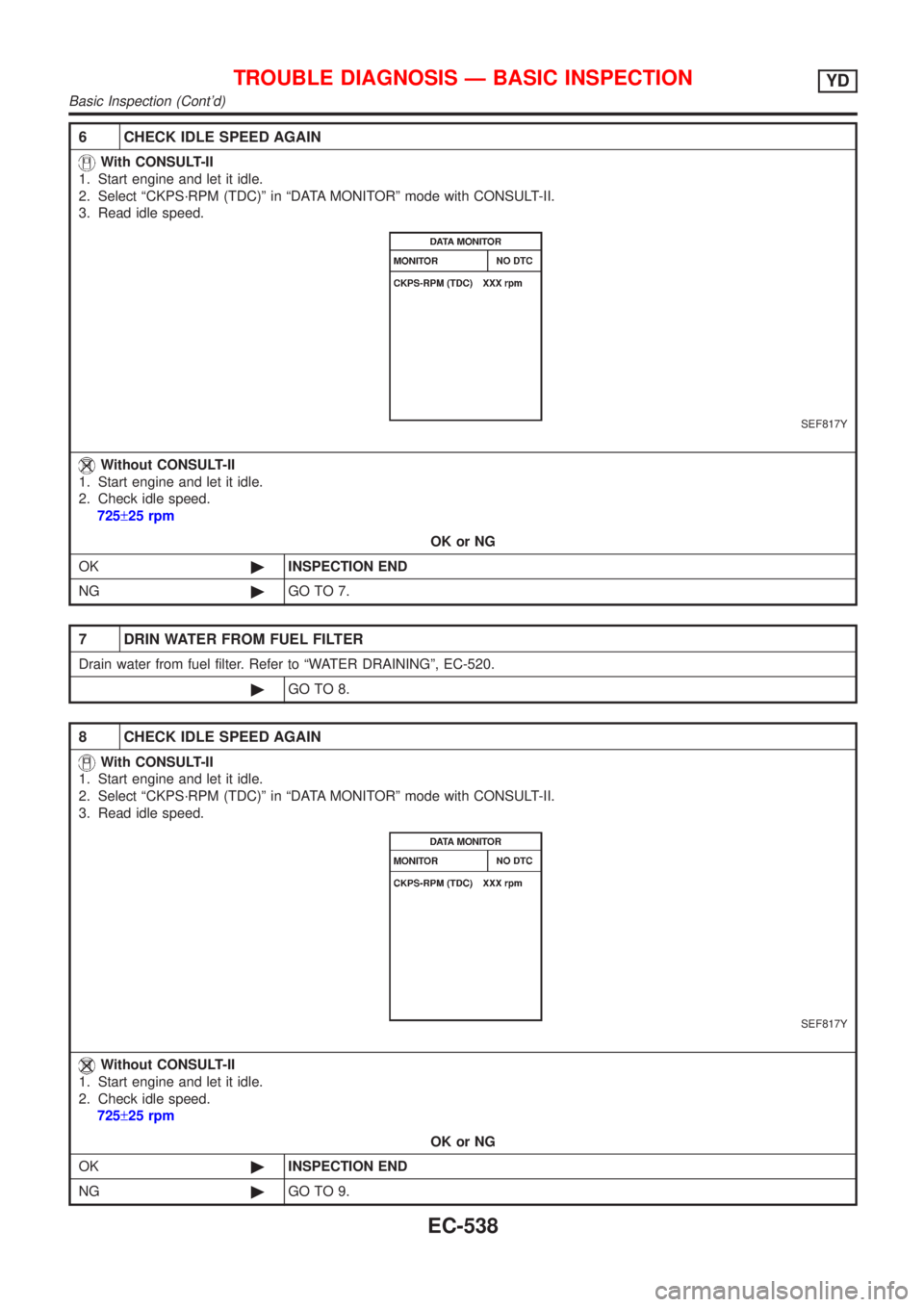
6 CHECK IDLE SPEED AGAIN
With CONSULT-II
1. Start engine and let it idle.
2. Select ªCKPS´RPM (TDC)º in ªDATA MONITORº mode with CONSULT-II.
3. Read idle speed.
SEF817Y
Without CONSULT-II
1. Start engine and let it idle.
2. Check idle speed.
725±25 rpm
OK or NG
OK©INSPECTION END
NG©GO TO 7.
7 DRIN WATER FROM FUEL FILTER
Drain water from fuel filter. Refer to ªWATER DRAININGº, EC-520.
©GO TO 8.
8 CHECK IDLE SPEED AGAIN
With CONSULT-II
1. Start engine and let it idle.
2. Select ªCKPS´RPM (TDC)º in ªDATA MONITORº mode with CONSULT-II.
3. Read idle speed.
SEF817Y
Without CONSULT-II
1. Start engine and let it idle.
2. Check idle speed.
725±25 rpm
OK or NG
OK©INSPECTION END
NG©GO TO 9.
TROUBLE DIAGNOSIS Ð BASIC INSPECTIONYD
Basic Inspection (Cont'd)
EC-538
Page 835 of 2493
9 CHECK AIR CLEANER FILTER
Check air cleaner filter for clogging or braks.
OK or NG
OK©GO TO 10.
NG©Replace air cleaner filter.
10 CHECK FUEL INJECTION NOZZLE
Check fuel injection nozzle opening pressure. Refer to ªInjection Pressure Testº, EC-512.
OK or NG
OK©GO TO 11.
NG©Replace fuel injection nozzle assembly.
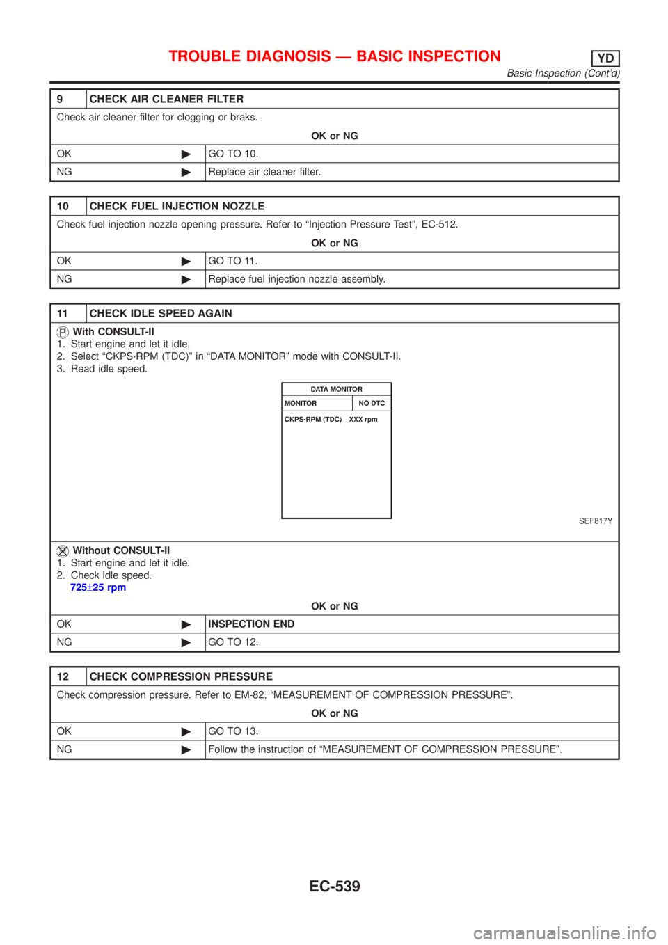
11 CHECK IDLE SPEED AGAIN
With CONSULT-II
1. Start engine and let it idle.
2. Select ªCKPS´RPM (TDC)º in ªDATA MONITORº mode with CONSULT-II.
3. Read idle speed.
SEF817Y
Without CONSULT-II
1. Start engine and let it idle.
2. Check idle speed.
725±25 rpm
OK or NG
OK©INSPECTION END
NG©GO TO 12.
12 CHECK COMPRESSION PRESSURE
Check compression pressure. Refer to EM-82, ªMEASUREMENT OF COMPRESSION PRESSUREº.
OK or NG
OK©GO TO 13.
NG©Follow the instruction of ªMEASUREMENT OF COMPRESSION PRESSUREº.
TROUBLE DIAGNOSIS Ð BASIC INSPECTIONYD
Basic Inspection (Cont'd)
EC-539
Page 999 of 2493
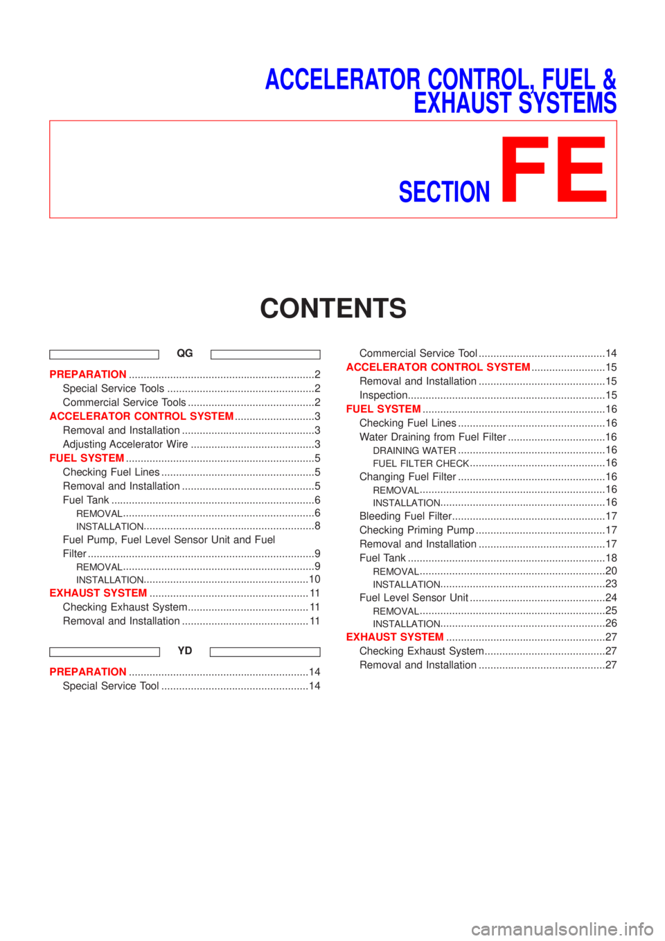
ACCELERATOR CONTROL, FUEL &
EXHAUST SYSTEMS
SECTION
FE
CONTENTS
QG
PREPARATION...............................................................2
Special Service Tools ..................................................2
Commercial Service Tools ...........................................2
ACCELERATOR CONTROL SYSTEM...........................3
Removal and Installation .............................................3
Adjusting Accelerator Wire ..........................................3
FUEL SYSTEM................................................................5
Checking Fuel Lines ....................................................5
Removal and Installation .............................................5
Fuel Tank .....................................................................6
REMOVAL.................................................................6
INSTALLATION..........................................................8
Fuel Pump, Fuel Level Sensor Unit and Fuel
Filter .............................................................................9
REMOVAL.................................................................9
INSTALLATION........................................................10
EXHAUST SYSTEM...................................................... 11
Checking Exhaust System......................................... 11
Removal and Installation ........................................... 11
YD
PREPARATION.............................................................14
Special Service Tool ..................................................14Commercial Service Tool ...........................................14
ACCELERATOR CONTROL SYSTEM.........................15
Removal and Installation ...........................................15
Inspection...................................................................15
FUEL SYSTEM..............................................................16
Checking Fuel Lines ..................................................16
Water Draining from Fuel Filter .................................16
DRAINING WATER..................................................16
FUEL FILTER CHECK..............................................16
Changing Fuel Filter ..................................................16
REMOVAL...............................................................16
INSTALLATION........................................................16
Bleeding Fuel Filter....................................................17
Checking Priming Pump ............................................17
Removal and Installation ...........................................17
Fuel Tank ...................................................................18
REMOVAL...............................................................20
INSTALLATION........................................................23
Fuel Level Sensor Unit ..............................................24
REMOVAL...............................................................25
INSTALLATION........................................................26
EXHAUST SYSTEM......................................................27
Checking Exhaust System.........................................27
Removal and Installation ...........................................27
Page 1007 of 2493
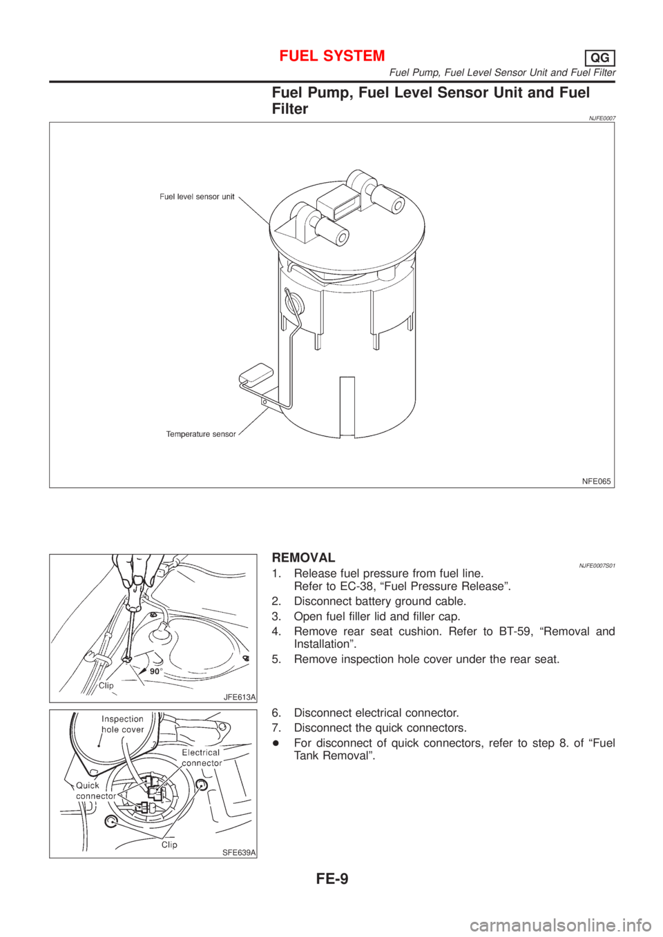
Fuel Pump, Fuel Level Sensor Unit and Fuel
Filter
NJFE0007
NFE065
JFE613A
REMOVALNJFE0007S011. Release fuel pressure from fuel line.
Refer to EC-38, ªFuel Pressure Releaseº.
2. Disconnect battery ground cable.
3. Open fuel filler lid and filler cap.
4. Remove rear seat cushion. Refer to BT-59, ªRemoval and
Installationº.
5. Remove inspection hole cover under the rear seat.
SFE639A
6. Disconnect electrical connector.
7. Disconnect the quick connectors.
+For disconnect of quick connectors, refer to step 8. of ªFuel
Tank Removalº.
FUEL SYSTEMQG
Fuel Pump, Fuel Level Sensor Unit and Fuel Filter
FE-9