2001 NISSAN ALMERA N16 fuel filter
[x] Cancel search: fuel filterPage 74 of 2493

Maintenance Under Severe Driving Conditions
(Annual Driving Distance > 30,000 km/year)
=NJMA0043S06The maintenance intervals shown on the preceding pages are for normal operating conditions. If the vehicle
is mainly operated under severe driving conditions as shown below, more frequent maintenance must be per-
formed on the following items as shown in the table.
A Ð Driving under dusty conditions
B Ð Driving repeatedly short distances
C Ð Towing a trailer or caravan
D Ð Extensive idling
E Ð Driving in extremely adverse weather conditions or in areas where ambient temperatures are either
extremely low or extremely high
F Ð Driving in high humidity areas or in mountainous areas
G Ð Driving in areas using salt or other corrosive materials
H Ð Driving on rough and/or muddy roads or in the desert
I Ð Driving with frequent use of braking or in mountainous areas
J Ð Frequent off road use or driving in water
K Ð Sustained high speed driving
L Ð For models without Euro-OBD system
Driving conditionMaintenance
itemMaintenance
operationMaintenance interval
ABCD........Engine oil & engine oil filter
Petrol models Replace Every 7,500 km (4,500 miles)
Diesel models Replace Every 10,000 km (6,000 miles)
A...........Air cleaner filter
Petrol models Replace Every 30,000 km (18,000 miles)
Diesel models Replace Every 30,000 km (18,000 miles)
A...E.......Fuel filter
Diesel models Replace Every 30,000 km (18,000 miles)
...........LHeated Oxygen Sensor 1 (Front)
Petrol models Inspect Every 60,000 km (36,000 miles)
...........LHeated Oxygen Sensor 2 (Rear)
Petrol models Inspect Every 60,000 km (36,000 miles)
A...........Ventilation air filter
Petrol models Replace Every 15,000 km (9,000 miles)
Diesel models Replace Every 10,000 km (6,000 miles)
.....F......Brake fluid
Petrol models Replace Every 30,000 km (18,000 miles)
Diesel models Replace Every 30,000 km (18,000 miles)
..C....H....Automatic transaxle fluid
Petrol models Replace Every 60,000 km (36,000 miles)
A.C...GHI...Brake pads, rotors & other brake system components
Petrol models Inspect Every 15,000 km (9,000 miles)
Diesel models Inspect Every 10,000 km (6,000 miles)
PERIODIC MAINTENANCE (FOR EUROPE)
Maintenance Under Severe Driving Conditions (Annual Driving Distance > 30,000 km/year)
MA-18
Page 80 of 2493

REPLACEMENT OF CONNECTING ROD
BUSHING (SMALL END)
..........................................60
FLYWHEEL/DRIVE PLATE RUNOUT........................60
Assembly ...................................................................60
PISTON..................................................................60
CRANKSHAFT.........................................................61
SERVICE DATA AND SPECIFICATIONS (SDS).........64
General Specifications ...............................................64
Compression Pressure ..............................................64
Belt Deflection............................................................64
Spark Plug .................................................................65
Cylinder Head ............................................................65
Valve ..........................................................................66
VALVE....................................................................66
VALVE SPRING.......................................................66
VALVE LIFTER........................................................66
VALVE CLEARANCE................................................67
VALVE GUIDE.........................................................67
AVAILABLE SHIMS..................................................67
VALVE SEAT...........................................................70
VALVE SEAT RESURFACE LIMIT.............................71
Camshaft and Camshaft Bearing ..............................71
Cylinder Block ............................................................72
Piston, Piston Ring and Piston Pin ...........................73
PISTON..................................................................73
PISTON RING.........................................................73
PISTON PIN............................................................73
Connecting Rod .........................................................74
Crankshaft..................................................................74
Main Bearing..............................................................74
STANDARD.............................................................74
UNDERSIZE............................................................74
Connecting Rod Bearing ...........................................75
STANDARD SIZE....................................................75
UNDERSIZE............................................................75
Bearing Clearance .....................................................75
Miscellaneous Components.......................................75
YD
PRECAUTIONS.............................................................76
Parts Requiring Angular Tightening ...........................76
Liquid Gasket Application Procedure ........................76
PREPARATION.............................................................77
Special Service Tools ................................................77
Commercial Service Tools .........................................79
NOISE, VIBRATION AND HARSHNESS (NVH)
TROUBLESHOOTING...................................................81
NVH Troubleshooting - Engine Noise .......................81
MEASUREMENT OF COMPRESSION PRESSURE....82
DRIVE BELTS................................................................84
Inspection...................................................................84
Adjustment .................................................................84
AIR CONDITIONER COMPRESSOR BELT................85
ALTERNATOR & WATER PUMP BELT.....................85
Removal .....................................................................85
Installation ..................................................................86
AIR CLEANER...............................................................87
Changing Air Cleaner Filter .......................................87
VISCOUS PAPER TYPE...........................................87
OIL PAN.........................................................................88
Components...............................................................88
Removal .....................................................................88
Installation ..................................................................90
TIMING CHAIN..............................................................93
Secondary Timing Chain ...........................................93
REMOVAL...............................................................93
INSPECTION...........................................................95
INSTALLATION........................................................95
Primary Timing Chain ................................................98
REMOVAL...............................................................99
INSPECTION.........................................................101
INSTALLATION......................................................101
INTAKE MANIFOLD....................................................106
Removal and Installation .........................................106
PREPARATIVE WORK...........................................106
FUEL PIPING........................................................107
INTAKE MANIFOLD...............................................107
EGR VOLUME CONTROL VALVE...........................107
WATER HOSE.......................................................107
Inspection.................................................................108
INTAKE MANIFOLD...............................................108
CATALYST..................................................................109
Removal and Installation .........................................109
PREPARATIVE WORK...........................................109
CATALYST............................................................109
GUSSET............................................................... 110
EXHAUST MANIFOLD, TURBOCHARGER............... 111
Removal and Installation ......................................... 111
PREPARATIVE WORK........................................... 111
EXHAUST MANIFOLD AND TURBOCHARGER....... 111
EXHAUST MANIFOLD GASKET............................. 112
Disassembly and Assembly ..................................... 112
TURBOCHARGER................................................. 112
Inspection................................................................. 113
EXHAUST MANIFOLD........................................... 113
TURBOCHARGER................................................. 113
ROCKER COVER........................................................ 116
Removal and Installation ......................................... 116
PREPARATIVE WORK........................................... 116
ROCKER COVER.................................................. 116
CYLINDER HEAD........................................................ 118
Components............................................................. 118
Removal ................................................................... 119
PREPARATIVE WORK........................................... 119
CAMSHAFT........................................................... 119
CYLINDER HEAD..................................................120
Disassembly.............................................................120
Inspection.................................................................121
CONTENTS(Cont'd)
EM-2
Page 303 of 2493

YD
TROUBLE DIAGNOSIS - INDEX................................492
Alphabetical & P No. Index for DTC .......................492
PRECAUTIONS...........................................................494
Supplemental Restraint System (SRS)²AIR
BAG²and²SEAT BELT PRE-TENSIONER²...........494
Engine Fuel & Emission Control System ................495
Precautions ..............................................................496
Wiring Diagrams and Trouble Diagnosis .................497
PREPARATION...........................................................498
Special Service Tools ..............................................498
ENGINE AND EMISSION CONTROL OVERALL
SYSTEM.......................................................................499
Engine Control Component Parts Location .............499
Circuit Diagram ........................................................502
System Diagram ......................................................503
System Chart ...........................................................504
ENGINE AND EMISSION BASIC CONTROL
SYSTEM DESCRIPTION.............................................505
Fuel Injection Control System .................................505
Fuel Injection Timing Control System......................506
Air Conditioning Cut Control ....................................507
Fuel Cut Control (at no load & high engine
speed) ......................................................................507
Crankcase Ventilation System .................................508
BASIC SERVICE PROCEDURE.................................509
Injection Tube and Injection Nozzle ........................509
Electronic Control Fuel Injection Pump ...................513
Fuel Filter .................................................................520
ON BOARD DIAGNOSTIC SYSTEM
DESCRIPTION.............................................................522
DTC and MI Detection Logic ...................................522
Diagnostic Trouble Code (DTC) ..............................522
Malfunction Indicator (MI) ........................................523
CONSULT-II .............................................................527
TROUBLE DIAGNOSIS - INTRODUCTION................532
Introduction ..............................................................532
Work Flow ................................................................534
TROUBLE DIAGNOSIS - BASIC INSPECTION.........536
Basic Inspection.......................................................536
TROUBLE DIAGNOSIS - GENERAL
DESCRIPTION.............................................................541
Symptom Matrix Chart .............................................541
CONSULT-II Reference Value in Data Monitor
Mode ........................................................................551
Major Sensor Reference Graph in Data Monitor
Mode ........................................................................553
ECM Terminals and Reference Value .....................554
TROUBLE DIAGNOSIS FOR INTERMITTENT
INCIDENT.....................................................................559
Description ...............................................................559
Diagnostic Procedure ..............................................559TROUBLE DIAGNOSIS FOR POWER SUPPLY........560
Main Power Supply and Ground Circuit ..................560
DTC P0100 MASS AIR FLOW SEN...........................566
Component Description ...........................................566
CONSULT-II Reference Value in Data Monitor
Mode ........................................................................566
ECM Terminals and Reference Value .....................566
On Board Diagnosis Logic.......................................566
DTC Confirmation Procedure ..................................566
Wiring Diagram ........................................................568
Diagnostic Procedure ..............................................569
DTC P0115 COOLANT TEMP SEN............................572
Description ...............................................................572
On Board Diagnosis Logic.......................................572
DTC Confirmation Procedure ..................................572
Wiring Diagram ........................................................574
Diagnostic Procedure ..............................................575
DTC P0120 ACCEL POS SENSOR............................577
Description ...............................................................577
CONSULT-II Reference Value in Data Monitor
Mode ........................................................................577
ECM Terminals and Reference Value .....................577
On Board Diagnosis Logic.......................................578
DTC Confirmation Procedure ..................................578
Wiring Diagram ........................................................579
Diagnostic Procedure ..............................................580
DTC P0335 CRANK POS SEN (TDC)........................587
Description ...............................................................587
CONSULT-II Reference Value in Data Monitor
Mode ........................................................................587
ECM Terminals and Reference Value .....................587
On Board Diagnosis Logic.......................................587
DTC Confirmation Procedure ..................................588
Wiring Diagram ........................................................589
Diagnostic Procedure ..............................................590
DTC P0500 VEHICLE SPEED SEN............................593
Description ...............................................................593
ECM Terminals and Reference Value .....................593
On Board Diagnosis Logic.......................................593
Overall Function Check ...........................................593
Wiring Diagram ........................................................595
Diagnostic Procedure ..............................................596
DTC P0571 BRAKE SW..............................................597
Description ...............................................................597
ECM Terminals and Reference Value .....................597
On Board Diagnosis Logic.......................................597
DTC Confirmation Procedure ..................................597
Wiring Diagram ........................................................599
Diagnostic Procedure ..............................................600
DTC P1107 ECM 10....................................................604
Description ...............................................................604
On Board Diagnosis Logic.......................................604
CONTENTS(Cont'd)
EC-7
Page 334 of 2493

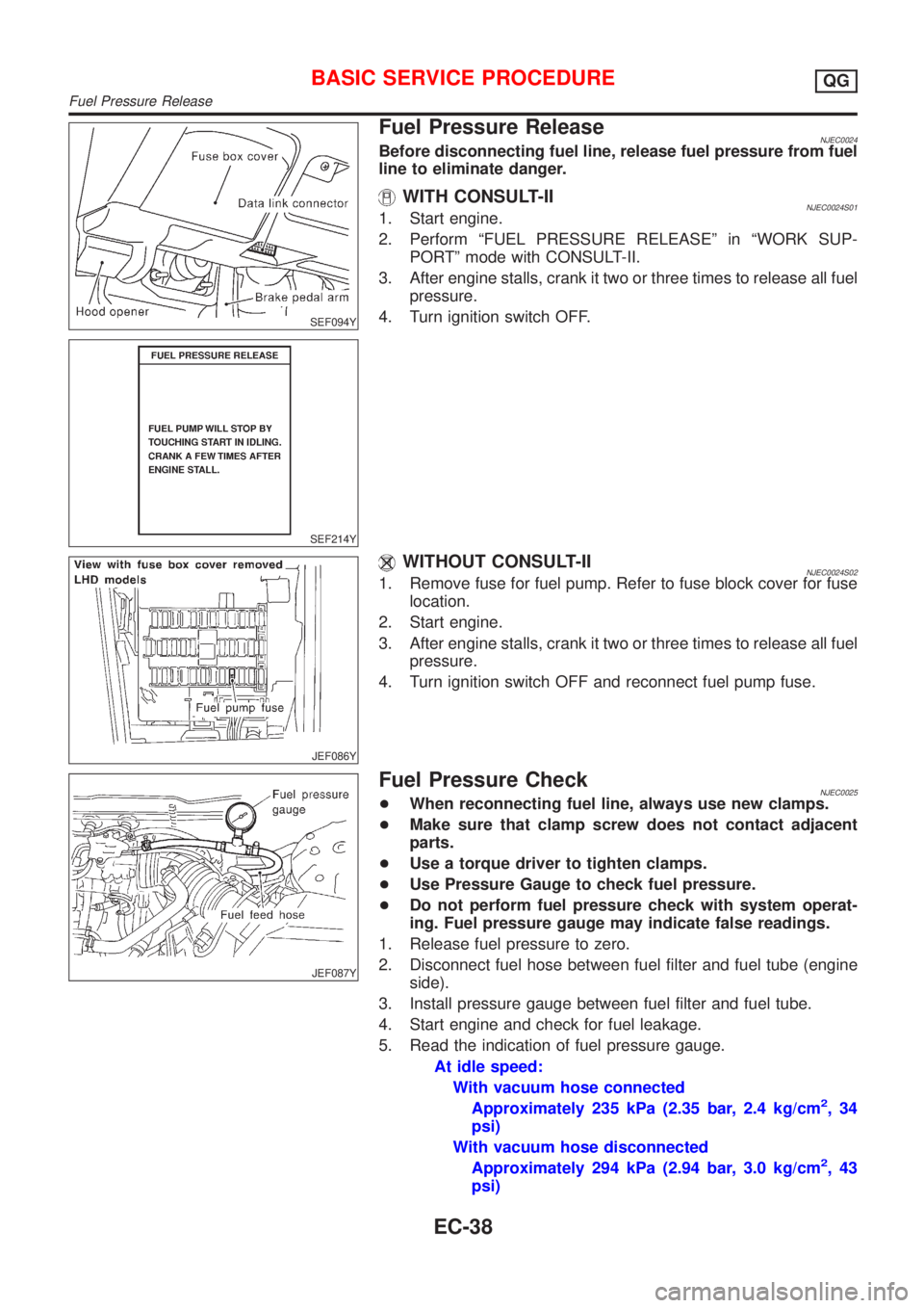
SEF094Y
SEF214Y
Fuel Pressure ReleaseNJEC0024Before disconnecting fuel line, release fuel pressure from fuel
line to eliminate danger.
WITH CONSULT-IINJEC0024S011. Start engine.
2. Perform ªFUEL PRESSURE RELEASEº in ªWORK SUP-
PORTº mode with CONSULT-II.
3. After engine stalls, crank it two or three times to release all fuel
pressure.
4. Turn ignition switch OFF.
JEF086Y
WITHOUT CONSULT-IINJEC0024S021. Remove fuse for fuel pump. Refer to fuse block cover for fuse
location.
2. Start engine.
3. After engine stalls, crank it two or three times to release all fuel
pressure.
4. Turn ignition switch OFF and reconnect fuel pump fuse.
JEF087Y
Fuel Pressure CheckNJEC0025+When reconnecting fuel line, always use new clamps.
+Make sure that clamp screw does not contact adjacent
parts.
+Use a torque driver to tighten clamps.
+Use Pressure Gauge to check fuel pressure.
+Do not perform fuel pressure check with system operat-
ing. Fuel pressure gauge may indicate false readings.
1. Release fuel pressure to zero.
2. Disconnect fuel hose between fuel filter and fuel tube (engine
side).
3. Install pressure gauge between fuel filter and fuel tube.
4. Start engine and check for fuel leakage.
5. Read the indication of fuel pressure gauge.
At idle speed:
With vacuum hose connected
Approximately 235 kPa (2.35 bar, 2.4 kg/cm
2,34
psi)
With vacuum hose disconnected
Approximately 294 kPa (2.94 bar, 3.0 kg/cm
2,43
psi)
BASIC SERVICE PROCEDUREQG
Fuel Pressure Release
EC-38
Page 423 of 2493

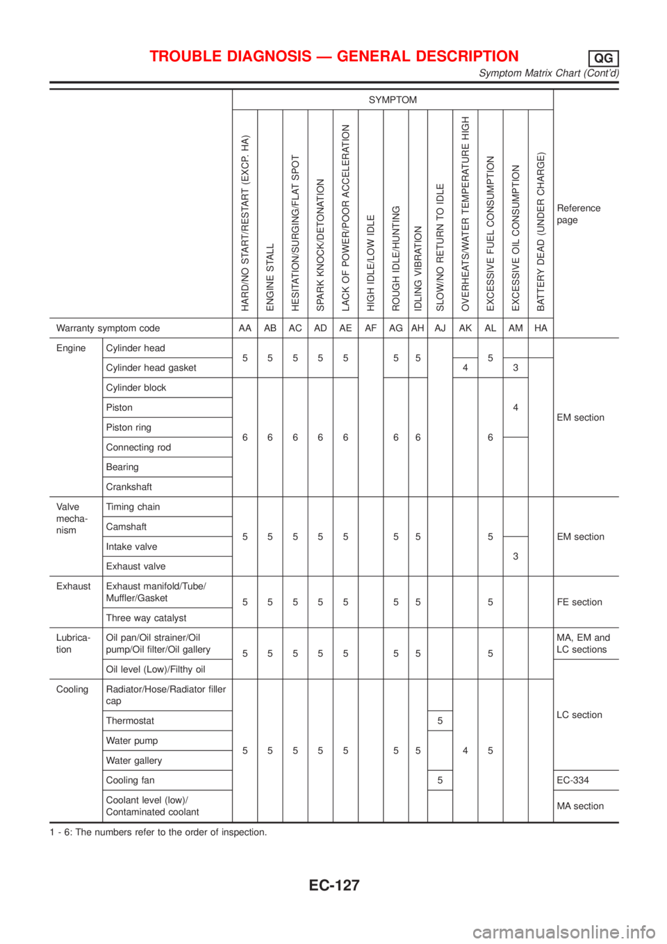
SYMPTOM
Reference
page
HARD/NO START/RESTART (EXCP. HA)
ENGINE STALL
HESITATION/SURGING/FLAT SPOT
SPARK KNOCK/DETONATION
LACK OF POWER/POOR ACCELERATION
HIGH IDLE/LOW IDLE
ROUGH IDLE/HUNTING
IDLING VIBRATION
SLOW/NO RETURN TO IDLE
OVERHEATS/WATER TEMPERATURE HIGH
EXCESSIVE FUEL CONSUMPTION
EXCESSIVE OIL CONSUMPTION
BATTERY DEAD (UNDER CHARGE)
Warranty symptom code AA AB AC AD AE AF AG AH AJ AK AL AM HA
Engine Cylinder head
55555 55 5
EM section Cylinder head gasket 4 3
Cylinder block
66666 66 64 Piston
Piston ring
Connecting rod
Bearing
Crankshaft
Valve
mecha-
nismTiming chain
55555 55 5 EMsection Camshaft
Intake valve
3
Exhaust valve
Exhaust Exhaust manifold/Tube/
Muffler/Gasket
55555 55 5 FEsection
Three way catalyst
Lubrica-
tionOil pan/Oil strainer/Oil
pump/Oil filter/Oil gallery
55555 55 5MA, EM and
LC sections
Oil level (Low)/Filthy oil
LC section Cooling Radiator/Hose/Radiator filler
cap
55555 55 45 Thermostat 5
Water pump
Water gallery
Cooling fan 5 EC-334
Coolant level (low)/
Contaminated coolantMA section
1 - 6: The numbers refer to the order of inspection.
TROUBLE DIAGNOSIS Ð GENERAL DESCRIPTIONQG
Symptom Matrix Chart (Cont'd)
EC-127
Page 548 of 2493

4 CHECK FUEL PRESSURE
1. Release fuel pressure to zero.
Refer to EC-38.
2. Install fuel pressure gauge and check fuel pressure.
At idling:
When fuel pressure regulator valve vacuum hose is connected.
235 kPa (2.35 bar, 2.4 kg/cm
2, 34 psi)
When fuel pressure regulator valve vacuum hose is disconnected.
294 kPa (2.94 bar, 3.0 kg/cm
2, 43 psi)
OK or NG
OK©GO TO 6.
NG©GO TO 5.
5 DETECT MALFUNCTIONING PART
Check the following.
+Fuel pump and circuit (Refer to EC-464.)
+Fuel pressure regulator (Refer to EC-39.)
+Fuel lines (Refer to ªENGINE MAINTENANCEº in MA section.)
+Fuel filter for clogging
©Repair or replace.
6 CHECK MASS AIR FLOW SENSOR
With CONSULT-II
Check ªMASS AIR FLOWº in ªDATA MONITORº mode with CONSULT-II.
at idling: 1.0 - 4.0 g´m/sec
at 2,500 rpm: 5.0 - 10.0 g´m/sec
With GST
Check mass air flow sensor signal in MODE 1 with GST.
at idling: 1.0 - 4.0 g´m/sec
at 2,500 rpm: 5.0 - 10.0 g´m/sec
OK or NG
OK©GO TO 7.
NG©Check connectors for rusted terminals or loose connections in the mass air flow sensor
circuit or engine grounds. Refer to EC-152.
DTC P0171 FUEL INJECTION SYSTEM FUNCTION (LEAN SIDE)QG
Diagnostic Procedure (Cont'd)
EC-252
Page 562 of 2493

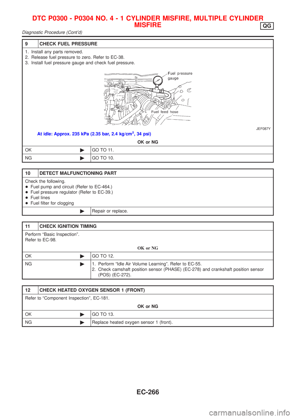
9 CHECK FUEL PRESSURE
1. Install any parts removed.
2. Release fuel pressure to zero. Refer to EC-38.
3. Install fuel pressure gauge and check fuel pressure.
JEF087Y
At idle: Approx. 235 kPa (2.35 bar, 2.4 kg/cm2, 34 psi)
OK or NG
OK©GO TO 11.
NG©GO TO 10.
10 DETECT MALFUNCTIONING PART
Check the following.
+Fuel pump and circuit (Refer to EC-464.)
+Fuel pressure regulator (Refer to EC-39.)
+Fuel lines
+Fuel filter for clogging
©Repair or replace.
11 CHECK IGNITION TIMING
Perform ªBasic Inspectionº.
Refer to EC-98.
OK or NG
OK©GO TO 12.
NG©1. Perform ªIdle Air Volume Learningº. Refer to EC-55.
2. Check camshaft position sensor (PHASE) (EC-278) and crankshaft position sensor
(POS) (EC-272).
12 CHECK HEATED OXYGEN SENSOR 1 (FRONT)
Refer to ªComponent Inspectionº, EC-181.
OK or NG
OK©GO TO 13.
NG©Replace heated oxygen sensor 1 (front).
DTC P0300 - P0304 NO.4-1CYLINDER MISFIRE, MULTIPLE CYLINDER
MISFIRE
QG
Diagnostic Procedure (Cont'd)
EC-266
Page 792 of 2493

SEF289H
PrecautionsNJEC0603+Before connecting or disconnecting the ECM harness
connector, turn ignition switch OFF and disconnect nega-
tive battery terminal. Failure to do so may damage the
ECM because battery voltage is applied to ECM even if
ignition switch is turned off.
SEF881Y
+When connecting ECM harness connectors, push in both
sides of the connector until you hear a click. Maneuver the
lever until you hear the three connectors on the inside
click. Refer to the figure at left.
SEF291H
+When connecting or disconnecting pin connectors into or
from ECM, take care not to damage pin terminals (bend or
break).
Make sure that there are not any bends or breaks on ECM
pin terminal, when connecting pin connectors.
MEF040D
+Before replacing ECM, perform Terminals and Reference
Value inspection and make sure ECM functions properly.
Refer to EC-554.
SAT652J
+If MI illuminates or blinks irregularly when engine is
running, water may have accumulated in fuel filter. Drain
water from fuel filter. If this does not correct the problem,
perform specified trouble diagnostic procedures.
+After performing each TROUBLE DIAGNOSIS, perform
ªDTC Confirmation Procedureº or ªOverall Function
Checkº.
The DTC should not be displayed in the ª DTC Confirma-
tion Procedureº if the repair is completed. The ªOverall
Function Checkº should be a good result if the repair is
completed.
PRECAUTIONSYD
Precautions
EC-496