2001 NISSAN ALMERA N16 Gauge
[x] Cancel search: GaugePage 1793 of 2493
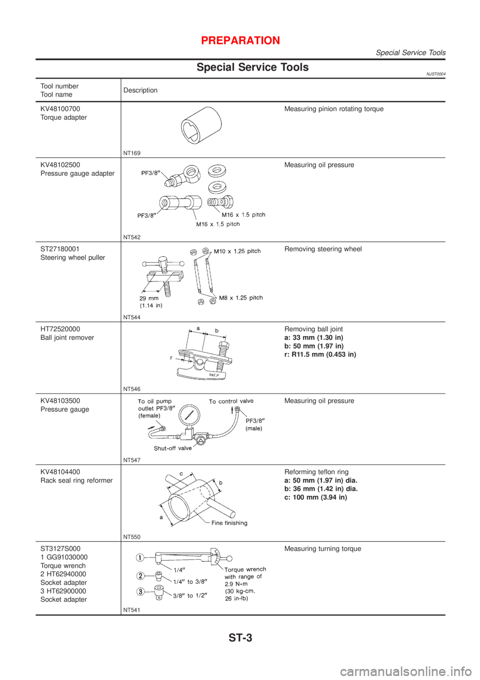
Special Service ToolsNJST0004
Tool number
Tool nameDescription
KV48100700
Torque adapter
NT169
Measuring pinion rotating torque
KV48102500
Pressure gauge adapter
NT542
Measuring oil pressure
ST27180001
Steering wheel puller
NT544
Removing steering wheel
HT72520000
Ball joint remover
NT546
Removing ball joint
a: 33 mm (1.30 in)
b: 50 mm (1.97 in)
r: R11.5 mm (0.453 in)
KV48103500
Pressure gauge
NT547
Measuring oil pressure
KV48104400
Rack seal ring reformer
NT550
Reforming teflon ring
a: 50 mm (1.97 in) dia.
b: 36 mm (1.42 in) dia.
c: 100 mm (3.94 in)
ST3127S000
1 GG91030000
Torque wrench
2 HT62940000
Socket adapter
3 HT62900000
Socket adapter
NT541
Measuring turning torque
PREPARATION
Special Service Tools
ST-3
Page 1968 of 2493
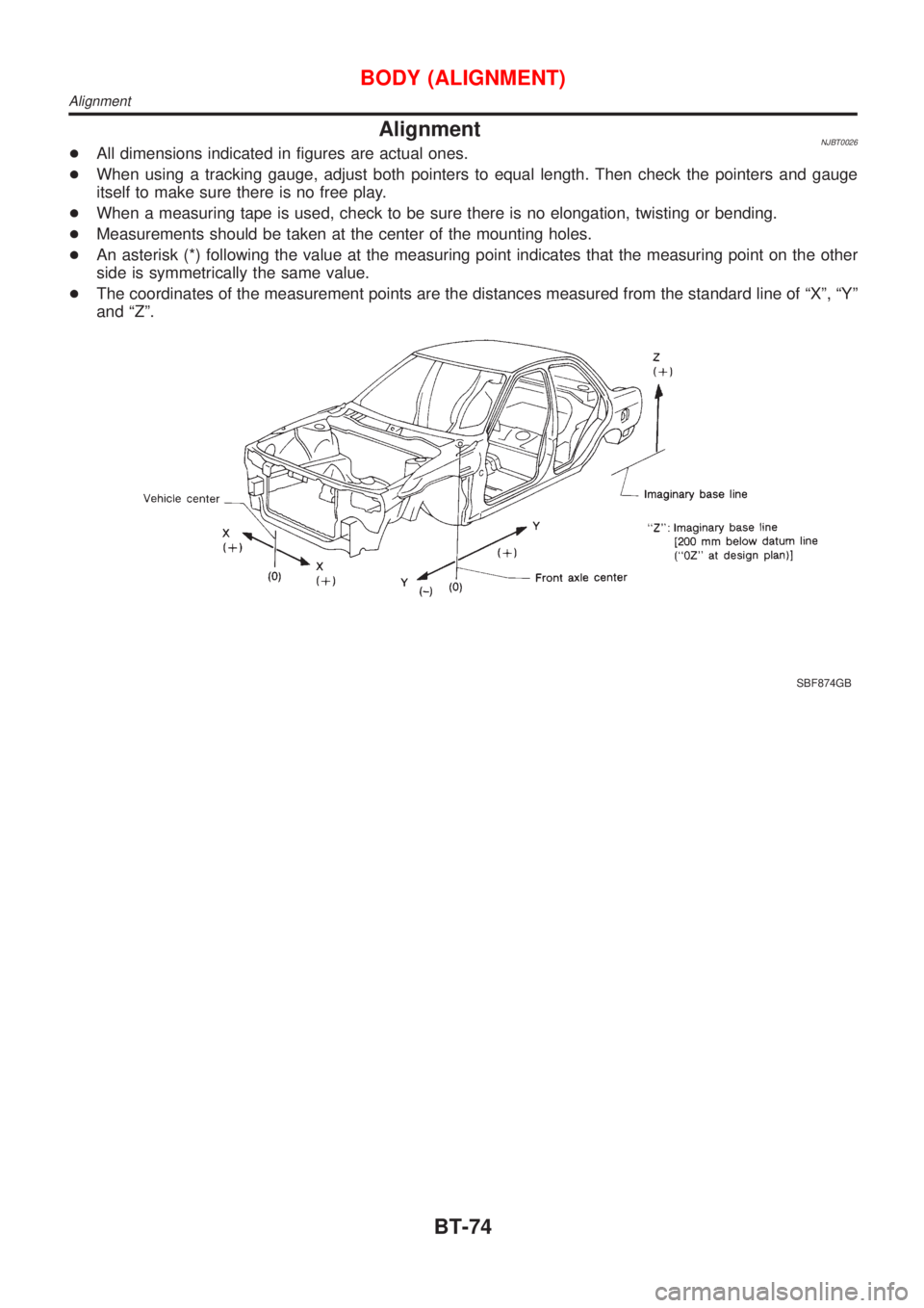
AlignmentNJBT0026+All dimensions indicated in figures are actual ones.
+When using a tracking gauge, adjust both pointers to equal length. Then check the pointers and gauge
itself to make sure there is no free play.
+When a measuring tape is used, check to be sure there is no elongation, twisting or bending.
+Measurements should be taken at the center of the mounting holes.
+An asterisk (*) following the value at the measuring point indicates that the measuring point on the other
side is symmetrically the same value.
+The coordinates of the measurement points are the distances measured from the standard line of ªXº, ªYº
and ªZº.
SBF874GB
BODY (ALIGNMENT)
Alignment
BT-74
Page 1978 of 2493
Precautions for Service EquipmentNJHA0117RECOVERY/RECYCLING EQUIPMENTNJHA0117S01Follow the manufacturer's instructions for machine operation and
machine maintenance. Never introduce any refrigerant other than
that specified into the machine.
ELECTRONIC LEAK DETECTORNJHA0117S02Follow the manufacture's instructions for tester operation and
tester maintenance.
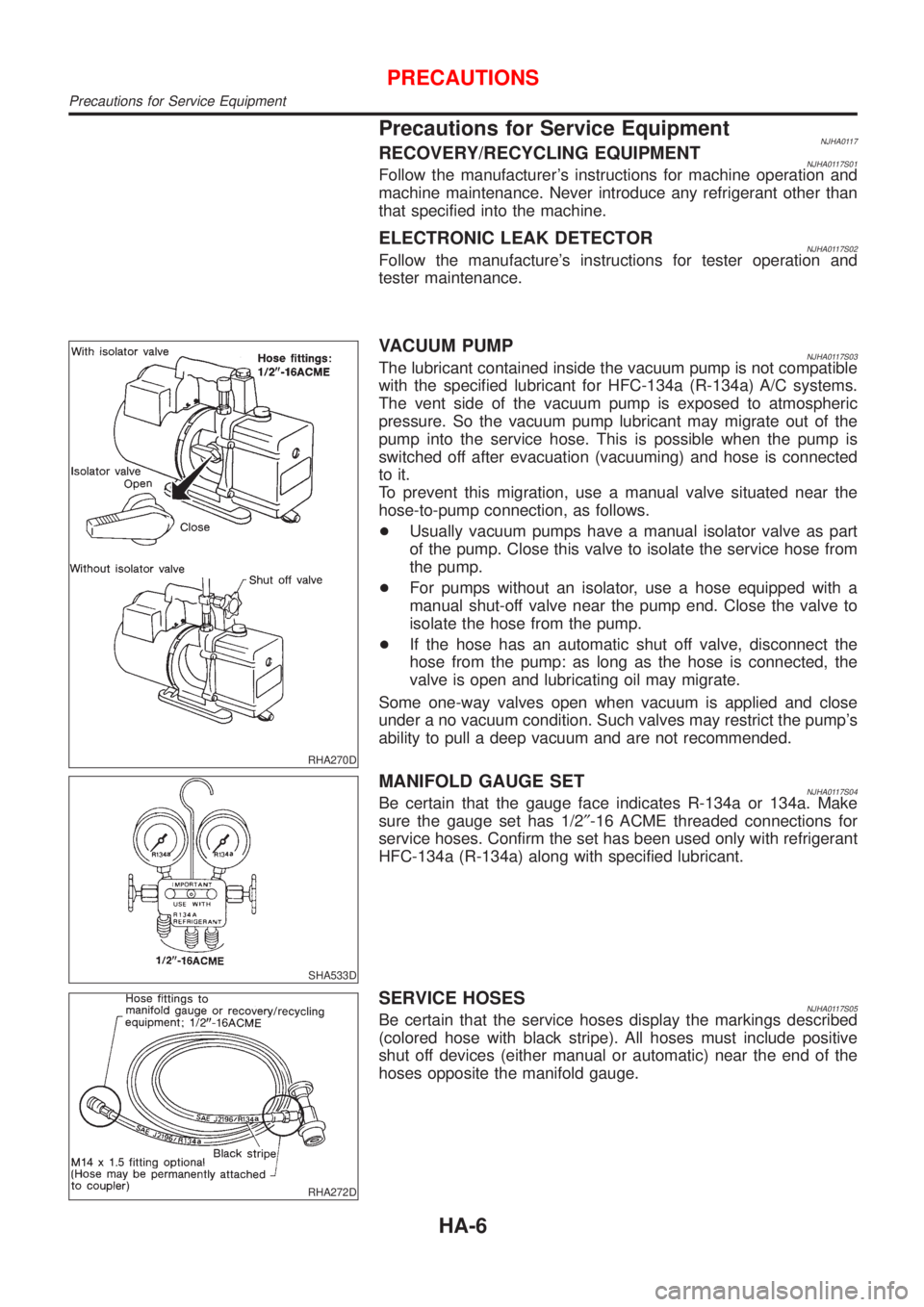
RHA270D
VACUUM PUMPNJHA0117S03The lubricant contained inside the vacuum pump is not compatible
with the specified lubricant for HFC-134a (R-134a) A/C systems.
The vent side of the vacuum pump is exposed to atmospheric
pressure. So the vacuum pump lubricant may migrate out of the
pump into the service hose. This is possible when the pump is
switched off after evacuation (vacuuming) and hose is connected
to it.
To prevent this migration, use a manual valve situated near the
hose-to-pump connection, as follows.
+Usually vacuum pumps have a manual isolator valve as part
of the pump. Close this valve to isolate the service hose from
the pump.
+For pumps without an isolator, use a hose equipped with a
manual shut-off valve near the pump end. Close the valve to
isolate the hose from the pump.
+If the hose has an automatic shut off valve, disconnect the
hose from the pump: as long as the hose is connected, the
valve is open and lubricating oil may migrate.
Some one-way valves open when vacuum is applied and close
under a no vacuum condition. Such valves may restrict the pump's
ability to pull a deep vacuum and are not recommended.
SHA533D
MANIFOLD GAUGE SETNJHA0117S04Be certain that the gauge face indicates R-134a or 134a. Make
sure the gauge set has 1/2²-16 ACME threaded connections for
service hoses. Confirm the set has been used only with refrigerant
HFC-134a (R-134a) along with specified lubricant.
RHA272D
SERVICE HOSESNJHA0117S05Be certain that the service hoses display the markings described
(colored hose with black stripe). All hoses must include positive
shut off devices (either manual or automatic) near the end of the
hoses opposite the manifold gauge.
PRECAUTIONS
Precautions for Service Equipment
HA-6
Page 1983 of 2493
HFC-134a (R-134a) Service Tools and
Equipment
=NJHA0120Never mix HFC-134a refrigerant and/or its specified lubricant with CFC-12 (R-12) refrigerant and/or its lubri-
cant.
Separate and non-interchangeable service equipment must be used for handling each type of refrigerant/
lubricant.
Refrigerant container fittings, service hose fittings and service equipment fittings (equipment which handles
refrigerant and/or lubricant) are different between CFC-12 (R-12) and HFC-134a (R-134a). This is to avoid
mixed use of the refrigerants/lubricant.
Adapters that convert one size fitting to another must never be used: refrigerant/lubricant contamination will
occur and compressor failure will result.
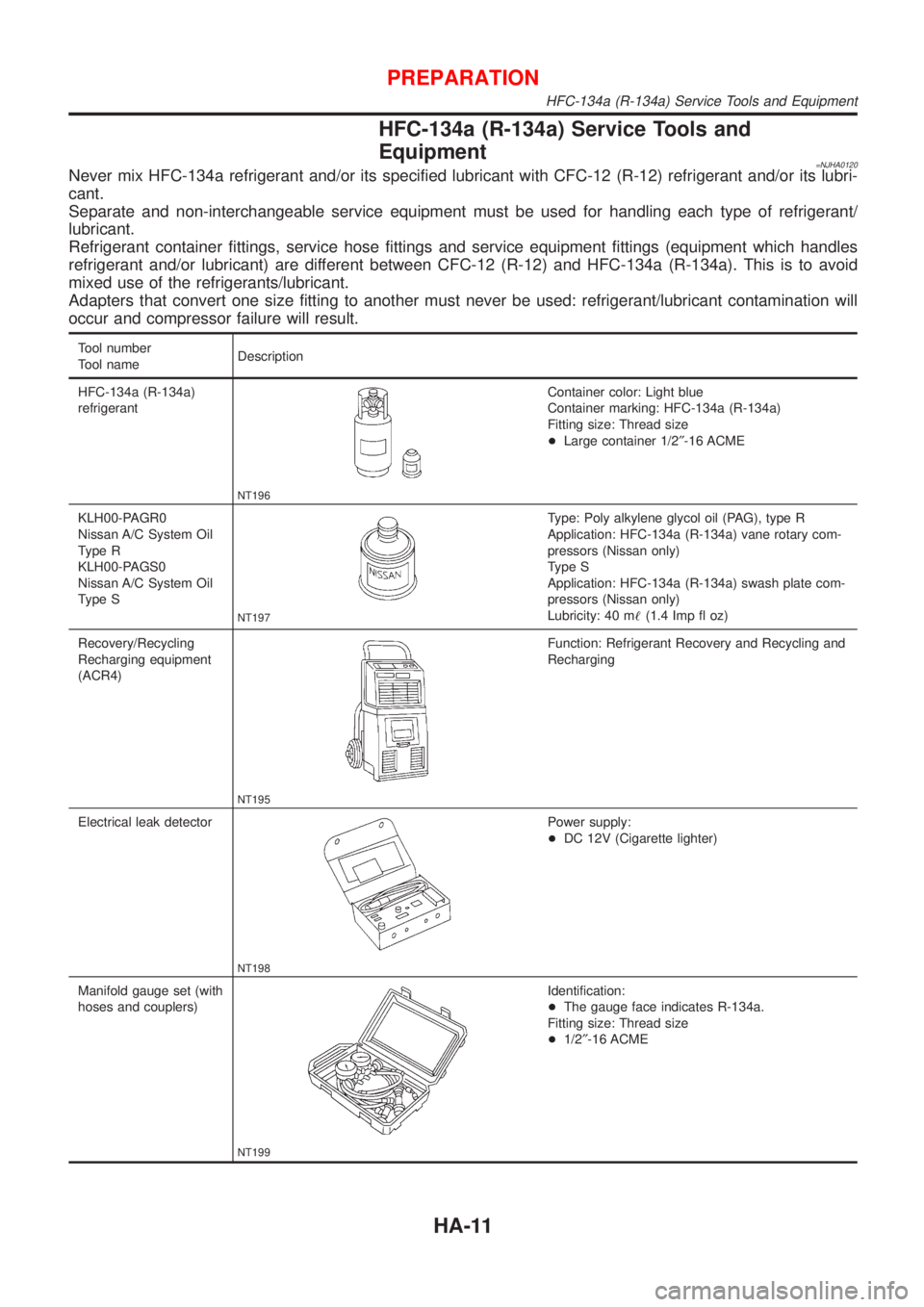
Tool number
Tool nameDescription
HFC-134a (R-134a)
refrigerant
NT196
Container color: Light blue
Container marking: HFC-134a (R-134a)
Fitting size: Thread size
+Large container 1/2²-16 ACME
KLH00-PAGR0
Nissan A/C System Oil
Type R
KLH00-PAGS0
Nissan A/C System Oil
Type S
NT197
Type: Poly alkylene glycol oil (PAG), type R
Application: HFC-134a (R-134a) vane rotary com-
pressors (Nissan only)
Type S
Application: HFC-134a (R-134a) swash plate com-
pressors (Nissan only)
Lubricity: 40 m!(1.4 Imp fl oz)
Recovery/Recycling
Recharging equipment
(ACR4)
NT195
Function: Refrigerant Recovery and Recycling and
Recharging
Electrical leak detector
NT198
Power supply:
+DC 12V (Cigarette lighter)
Manifold gauge set (with
hoses and couplers)
NT199
Identification:
+The gauge face indicates R-134a.
Fitting size: Thread size
+1/2²-16 ACME
PREPARATION
HFC-134a (R-134a) Service Tools and Equipment
HA-11
Page 1984 of 2493
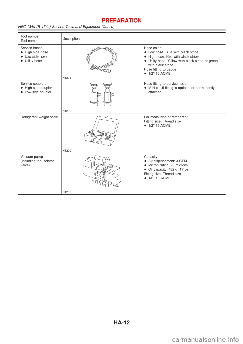
Tool number
Tool nameDescription
Service hoses
+High side hose
+Low side hose
+Utility hose
NT201
Hose color:
+Low hose: Blue with black stripe
+High hose: Red with black stripe
+Utility hose: Yellow with black stripe or green
with black stripe
Hose fitting to gauge:
+1/2²-16 ACME
Service couplers
+High side coupler
+Low side coupler
NT202
Hose fitting to service hose:
+M14 x 1.5 fitting is optional or permanently
attached.
Refrigerant weight scale
NT200
For measuring of refrigerant
Fitting size: Thread size
+1/2²-16 ACME
Vacuum pump
(Including the isolator
valve)
NT203
Capacity:
+Air displacement: 4 CFM
+Micron rating: 20 microns
+Oil capacity: 482 g (17 oz)
Fitting size: Thread size
+1/2²-16 ACME
PREPARATION
HFC-134a (R-134a) Service Tools and Equipment (Cont'd)
HA-12
Page 2050 of 2493
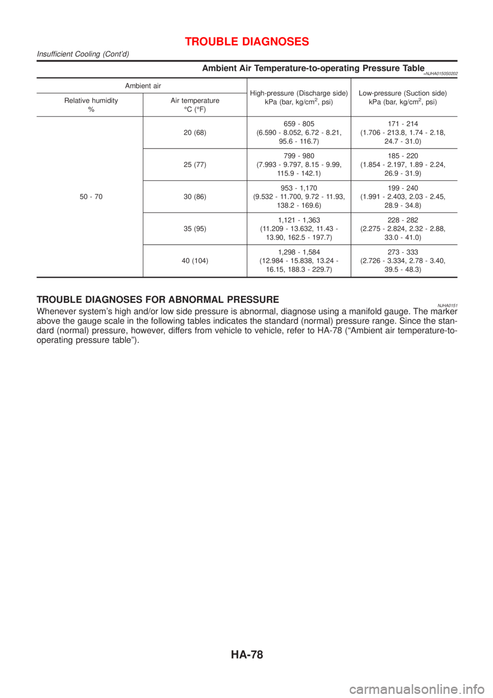
Ambient Air Temperature-to-operating Pressure Table=NJHA0150S0202
Ambient air
High-pressure (Discharge side)
kPa (bar, kg/cm
2, psi)Low-pressure (Suction side)
kPa (bar, kg/cm2, psi) Relative humidity
%Air temperature
ÉC (ÉF)
50-7020 (68)659 - 805
(6.590 - 8.052, 6.72 - 8.21,
95.6 - 116.7)171 - 214
(1.706 - 213.8, 1.74 - 2.18,
24.7 - 31.0)
25 (77)799 - 980
(7.993 - 9.797, 8.15 - 9.99,
115.9 - 142.1)185 - 220
(1.854 - 2.197, 1.89 - 2.24,
26.9 - 31.9)
30 (86)953 - 1,170
(9.532 - 11.700, 9.72 - 11.93,
138.2 - 169.6)199 - 240
(1.991 - 2.403, 2.03 - 2.45,
28.9 - 34.8)
35 (95)1,121 - 1,363
(11.209 - 13.632, 11.43 -
13.90, 162.5 - 197.7)228 - 282
(2.275 - 2.824, 2.32 - 2.88,
33.0 - 41.0)
40 (104)1,298 - 1,584
(12.984 - 15.838, 13.24 -
16.15, 188.3 - 229.7)273 - 333
(2.726 - 3.334, 2.78 - 3.40,
39.5 - 48.3)
TROUBLE DIAGNOSES FOR ABNORMAL PRESSURENJHA0151Whenever system's high and/or low side pressure is abnormal, diagnose using a manifold gauge. The marker
above the gauge scale in the following tables indicates the standard (normal) pressure range. Since the stan-
dard (normal) pressure, however, differs from vehicle to vehicle, refer to HA-78 (ªAmbient air temperature-to-
operating pressure tableº).
TROUBLE DIAGNOSES
Insufficient Cooling (Cont'd)
HA-78
Page 2051 of 2493
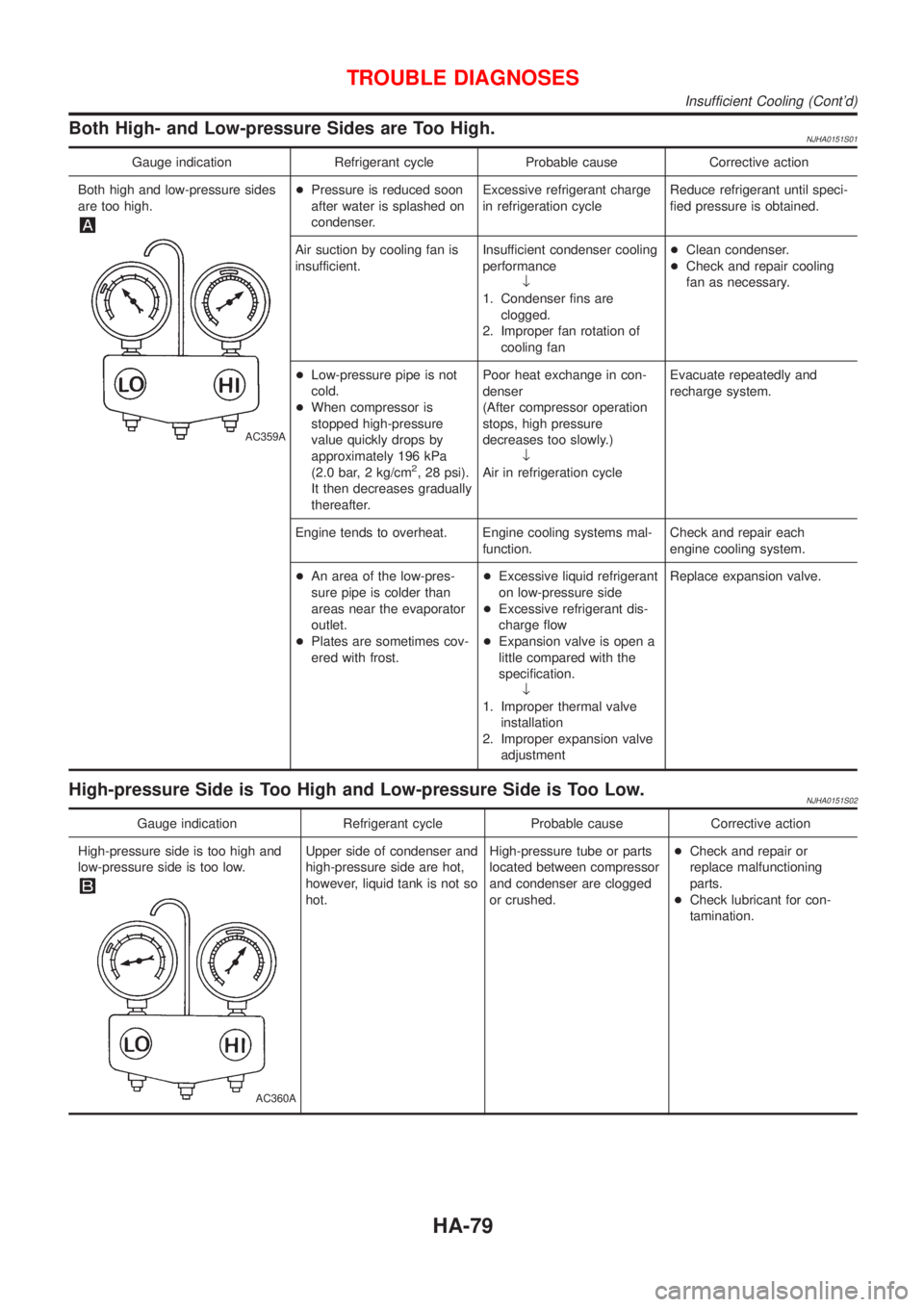
Both High- and Low-pressure Sides are Too High.NJHA0151S01
Gauge indication Refrigerant cycle Probable cause Corrective action
Both high and low-pressure sides
are too high.
AC359A
+Pressure is reduced soon
after water is splashed on
condenser.Excessive refrigerant charge
in refrigeration cycleReduce refrigerant until speci-
fied pressure is obtained.
Air suction by cooling fan is
insufficient.Insufficient condenser cooling
performance
¯
1. Condenser fins are
clogged.
2. Improper fan rotation of
cooling fan+Clean condenser.
+Check and repair cooling
fan as necessary.
+Low-pressure pipe is not
cold.
+When compressor is
stopped high-pressure
value quickly drops by
approximately 196 kPa
(2.0 bar, 2 kg/cm
2, 28 psi).
It then decreases gradually
thereafter.Poor heat exchange in con-
denser
(After compressor operation
stops, high pressure
decreases too slowly.)
¯
Air in refrigeration cycleEvacuate repeatedly and
recharge system.
Engine tends to overheat. Engine cooling systems mal-
function.Check and repair each
engine cooling system.
+An area of the low-pres-
sure pipe is colder than
areas near the evaporator
outlet.
+Plates are sometimes cov-
ered with frost.+Excessive liquid refrigerant
on low-pressure side
+Excessive refrigerant dis-
charge flow
+Expansion valve is open a
little compared with the
specification.
¯
1. Improper thermal valve
installation
2. Improper expansion valve
adjustmentReplace expansion valve.
High-pressure Side is Too High and Low-pressure Side is Too Low.NJHA0151S02
Gauge indication Refrigerant cycle Probable cause Corrective action
High-pressure side is too high and
low-pressure side is too low.
AC360A
Upper side of condenser and
high-pressure side are hot,
however, liquid tank is not so
hot.High-pressure tube or parts
located between compressor
and condenser are clogged
or crushed.+Check and repair or
replace malfunctioning
parts.
+Check lubricant for con-
tamination.
TROUBLE DIAGNOSES
Insufficient Cooling (Cont'd)
HA-79
Page 2052 of 2493
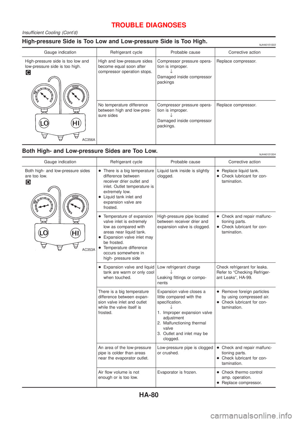
High-pressure Side is Too Low and Low-pressure Side is Too High.NJHA0151S03
Gauge indication Refrigerant cycle Probable cause Corrective action
High-pressure side is too low and
low-pressure side is too high.
AC356A
High and low-pressure sides
become equal soon after
compressor operation stops.Compressor pressure opera-
tion is improper.
¯
Damaged inside compressor
packingsReplace compressor.
No temperature difference
between high and low-pres-
sure sidesCompressor pressure opera-
tion is improper.
¯
Damaged inside compressor
packings.Replace compressor.
Both High- and Low-pressure Sides are Too Low.NJHA0151S04
Gauge indication Refrigerant cycle Probable cause Corrective action
Both high- and low-pressure sides
are too low.
AC353A
+There is a big temperature
difference between
receiver drier outlet and
inlet. Outlet temperature is
extremely low.
+Liquid tank inlet and
expansion valve are
frosted.Liquid tank inside is slightly
clogged.+Replace liquid tank.
+Check lubricant for con-
tamination.
+Temperature of expansion
valve inlet is extremely
low as compared with
areas near liquid tank.
+Expansion valve inlet may
be frosted.
+Temperature difference
occurs somewhere in
high- pressure sideHigh-pressure pipe located
between receiver drier and
expansion valve is clogged.+Check and repair malfunc-
tioning parts.
+Check lubricant for con-
tamination.
+Expansion valve and liquid
tank are warm or only cool
when touched.Low refrigerant charge
¯
Leaking fittings or compo-
nentsCheck refrigerant for leaks.
Refer to ªChecking Refriger-
ant Leaksº, HA-99.
There is a big temperature
difference between expan-
sion valve inlet and outlet
while the valve itself is
frosted.Expansion valve closes a
little compared with the
specification.
¯
1. Improper expansion valve
adjustment
2. Malfunctioning thermal
valve
3. Outlet and inlet may be
clogged.+Remove foreign particles
by using compressed air.
+Check lubricant for con-
tamination.
An area of the low-pressure
pipe is colder than areas
near the evaporator outlet.Low-pressure pipe is clogged
or crushed.+Check and repair malfunc-
tioning parts.
+Check lubricant for con-
tamination.
Air flow volume is not
enough or is too low.Evaporator is frozen.+Check thermo control
amp. operation.
+Replace compressor.
TROUBLE DIAGNOSES
Insufficient Cooling (Cont'd)
HA-80