Page 1619 of 2493

SAT438D
2. Install output shaft thrust needle bearing on bearing retainer.
SAT439D
3. Install output shaft on transmission case.
SAT874DA
4. Measure dimensions ª!1º and ª!2º at side cover and then cal-
culate dimension ªAº.
+Measure dimension ª!
1º and ª!2º in at least two places
ªAº: Distance between transmission case fitting surface
and adjusting shim mating surface
A=!
1þ!2
!2: Height of gauge
SAT875DA
5. Measure dimensions ª!2º and ª!3º and then calculate dimen-
sion ªBº.
Measure ª!
2º and ª!3º in at least two places.
ªBº: Distance between the end of output shaft bearing
outer race and the side cover fitting surface of transmis-
sion case
B=!
2þ!3
!2: Height of gauge
SAT440D
6. Select proper thickness of adjusting shim so that output shaft
end play (clearance between side cover and output shaft bear-
ing) is within specifications.
Output shaft end play (A þ B):
0 - 0.5 mm (0 - 0.020 in)
Output shaft end play adjusting shim:
Refer to SDS, AT-456.
7. Install adjusting shim on output shaft bearing.
ASSEMBLY
Adjustment (1) (Cont'd)
AT-433
Page 1626 of 2493
SAT379D
b. Measure dimension ªMº.
ªMº: Distance between transmission case fitting surface
and needle bearing on oil pump cover
ªM
1º: Indication of gauge
SAT443D
c. Measure thickness of straightedge ªtº.
M=M
1þt
3. Adjust total end play ªT
3º.
T
3=JþM
Total end play ªT
3º:
0.25 - 0.55 mm (0.0098 - 0.0217 in)
+Select proper thickness of bearing race so that total end play
is within specifications.
Bearing races: Refer to SDS, AT-457.
SAT380D
REVERSE CLUTCH END PLAYNJAT0176S02+Measure clearance between oil pump cover and thrust washer
for reverse clutch drum.
+Select proper thickness of thrust washer so that end play is
within specifications.
SAT381D
1. Measure dimensions ªOº and ªPº and then calculate dimension
ªNº.
ASSEMBLY
Adjustment (2) (Cont'd)
AT-440
Page 1679 of 2493

SFA975B
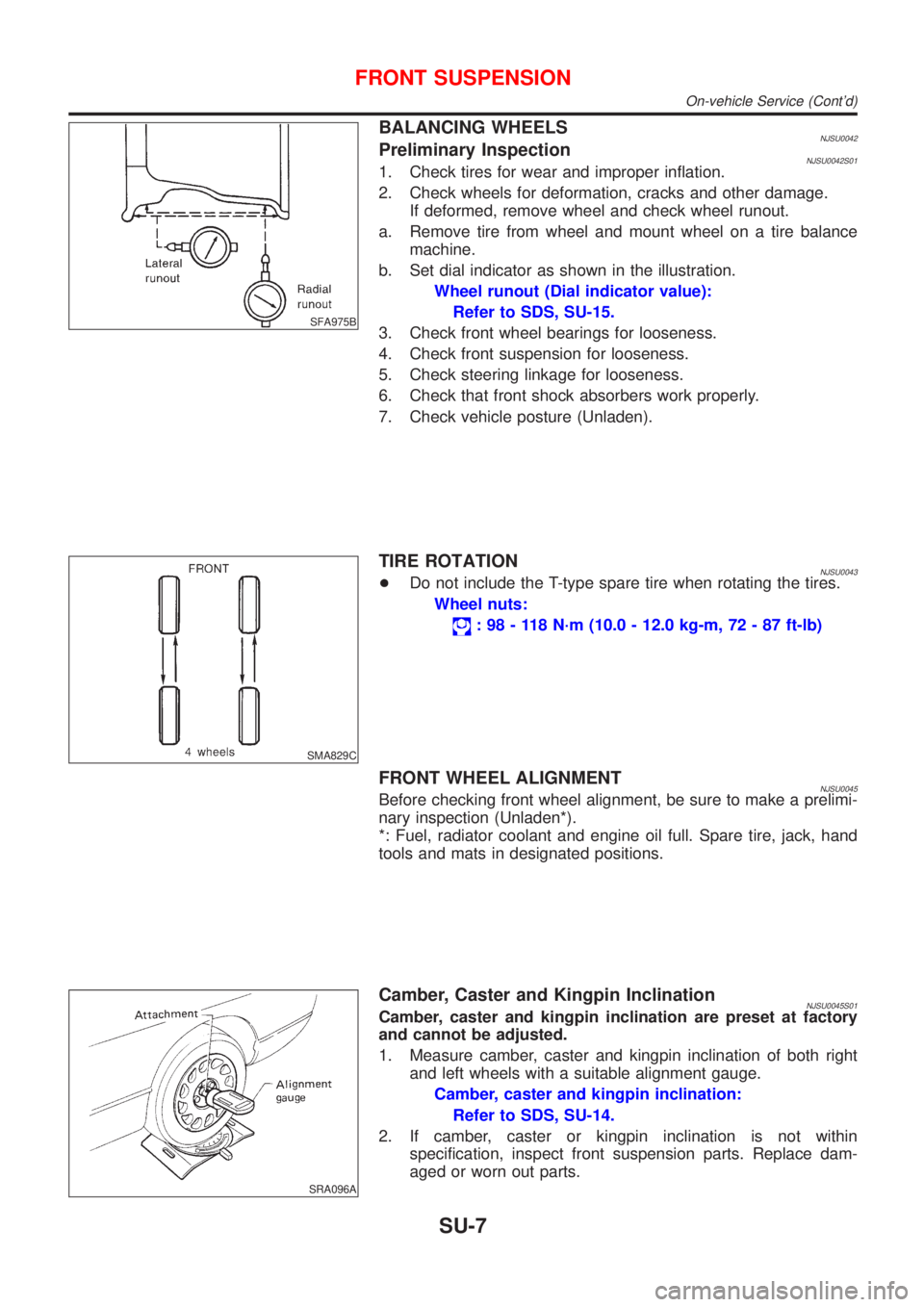
BALANCING WHEELSNJSU0042Preliminary InspectionNJSU0042S011. Check tires for wear and improper inflation.
2. Check wheels for deformation, cracks and other damage.
If deformed, remove wheel and check wheel runout.
a. Remove tire from wheel and mount wheel on a tire balance
machine.
b. Set dial indicator as shown in the illustration.
Wheel runout (Dial indicator value):
Refer to SDS, SU-15.
3. Check front wheel bearings for looseness.
4. Check front suspension for looseness.
5. Check steering linkage for looseness.
6. Check that front shock absorbers work properly.
7. Check vehicle posture (Unladen).
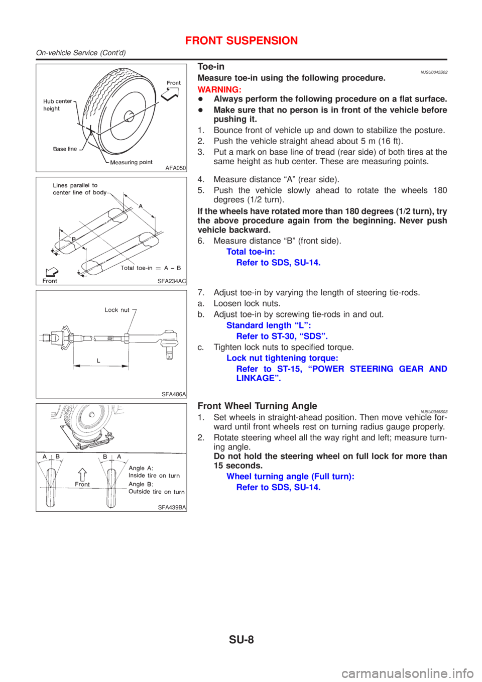
SMA829C
TIRE ROTATIONNJSU0043+Do not include the T-type spare tire when rotating the tires.
Wheel nuts:
: 98 - 118 N´m (10.0 - 12.0 kg-m, 72 - 87 ft-lb)
FRONT WHEEL ALIGNMENTNJSU0045Before checking front wheel alignment, be sure to make a prelimi-
nary inspection (Unladen*).
*: Fuel, radiator coolant and engine oil full. Spare tire, jack, hand
tools and mats in designated positions.
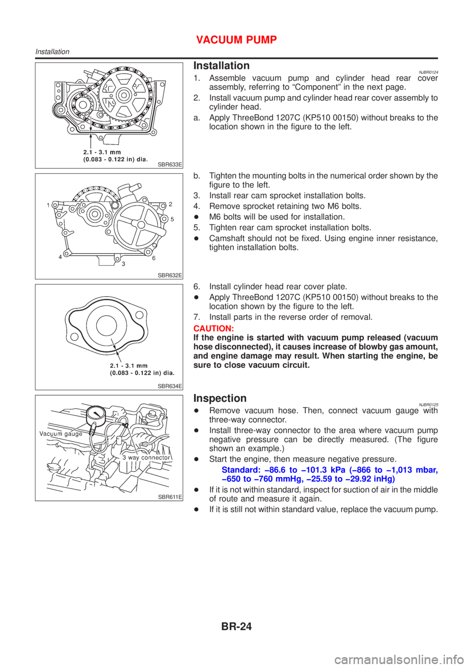
SRA096A
Camber, Caster and Kingpin InclinationNJSU0045S01Camber, caster and kingpin inclination are preset at factory
and cannot be adjusted.
1. Measure camber, caster and kingpin inclination of both right
and left wheels with a suitable alignment gauge.
Camber, caster and kingpin inclination:
Refer to SDS, SU-14.
2. If camber, caster or kingpin inclination is not within
specification, inspect front suspension parts. Replace dam-
aged or worn out parts.
FRONT SUSPENSION
On-vehicle Service (Cont'd)
SU-7
Page 1680 of 2493

AFA050
Toe-inNJSU0045S02Measure toe-in using the following procedure.
WARNING:
+Always perform the following procedure on a flat surface.
+Make sure that no person is in front of the vehicle before
pushing it.
1. Bounce front of vehicle up and down to stabilize the posture.
2. Push the vehicle straight ahead about 5 m (16 ft).
3. Put a mark on base line of tread (rear side) of both tires at the
same height as hub center. These are measuring points.
SFA234AC
4. Measure distance ªAº (rear side).
5. Push the vehicle slowly ahead to rotate the wheels 180
degrees (1/2 turn).
If the wheels have rotated more than 180 degrees (1/2 turn), try
the above procedure again from the beginning. Never push
vehicle backward.
6. Measure distance ªBº (front side).
Total toe-in:
Refer to SDS, SU-14.
SFA486A
7. Adjust toe-in by varying the length of steering tie-rods.
a. Loosen lock nuts.
b. Adjust toe-in by screwing tie-rods in and out.
Standard length ªLº:
Refer to ST-30, ªSDSº.
c. Tighten lock nuts to specified torque.
Lock nut tightening torque:
Refer to ST-15, ªPOWER STEERING GEAR AND
LINKAGEº.
SFA439BA
Front Wheel Turning AngleNJSU0045S031. Set wheels in straight-ahead position. Then move vehicle for-
ward until front wheels rest on turning radius gauge properly.
2. Rotate steering wheel all the way right and left; measure turn-
ing angle.
Do not hold the steering wheel on full lock for more than
15 seconds.
Wheel turning angle (Full turn):
Refer to SDS, SU-14.
FRONT SUSPENSION
On-vehicle Service (Cont'd)
SU-8
Page 1703 of 2493
Commercial Service ToolsNJBR0004
Tool name Description
1 Flare nut crowfoot
2 Torque wrench
NT360
Removing and installing each brake piping
a: 10 mm (0.39 in)
Brake fluid pressure
gauge
NT151
Measuring brake fluid pressure
PREPARATION
Commercial Service Tools
BR-5
Page 1722 of 2493

SBR633E
InstallationNJBR01241. Assemble vacuum pump and cylinder head rear cover
assembly, referring to ªComponentº in the next page.
2. Install vacuum pump and cylinder head rear cover assembly to
cylinder head.
a. Apply ThreeBond 1207C (KP510 00150) without breaks to the
location shown in the figure to the left.
SBR632E
b. Tighten the mounting bolts in the numerical order shown by the
figure to the left.
3. Install rear cam sprocket installation bolts.
4. Remove sprocket retaining two M6 bolts.
+M6 bolts will be used for installation.
5. Tighten rear cam sprocket installation bolts.
+Camshaft should not be fixed. Using engine inner resistance,
tighten installation bolts.
SBR634E
6. Install cylinder head rear cover plate.
+Apply ThreeBond 1207C (KP510 00150) without breaks to the
location shown by the figure to the left.
7. Install parts in the reverse order of removal.
CAUTION:
If the engine is started with vacuum pump released (vacuum
hose disconnected), it causes increase of blowby gas amount,
and engine damage may result. When starting the engine, be
sure to close vacuum circuit.
SBR611E
InspectionNJBR0125+Remove vacuum hose. Then, connect vacuum gauge with
three-way connector.
+Install three-way connector to the area where vacuum pump
negative pressure can be directly measured. (The figure
shown an example.)
+Start the engine, then measure negative pressure.
Standard: þ86.6 to þ101.3 kPa (þ866 to þ1,013 mbar,
þ650 to þ760 mmHg, þ25.59 to þ29.92 inHg)
+If it is not within standard, inspect for suction of air in the middle
of route and measure it again.
+If it is still not within standard value, replace the vacuum pump.
VACUUM PUMP
Installation
BR-24
Page 1723 of 2493
ComponentNJBR0126
SBR612E
SBR613E
DisassemblyNJBR0136Disassemble the components, referring to the ªComponentº, then
remove vacuum pump.
CAUTION:
Do not disassemble vacuum pump. (Do not loosen three M6
bolts.)
AssemblyNJBR0127Install all parts to cylinder head rear cover as follows.
1. Install vacuum pump.
2. Install chain guide temporarily.
+Adjust the chain guide position by the method explained in step
5.
SBR614E
3. Install rear cam sprocket.
+Installation direction of sprocket is not specified.
+Insert 2 thickness gauges [3.0 mm (0.118 in)] between cover
and rear cam sprocket (shown in the figure). Insert 2 bolts [M6,
thread length: 35 - 40 mm (1.38 - 1.57 in)] into sprocket to
retain it to cover.
+Use thickness gauges [3.0 mm (0.118 in)] for chain alignment
between vacuum pump sprocket and cam sprocket.
4. Attach drive chain to rear cam sprocket and vacuum pump
sprocket.
5. Tighten chain guide installation bolt while pressing chain guide
VACUUM PUMP
Component
BR-25
Page 1724 of 2493
lightly [approximately 9.8 N (1.0 kg, 2.2 lb)].
6. Remove thickness gauges (2).
+Leave sprocket retaining bolts (M6) until installation.
VACUUM PUMP
Assembly (Cont'd)
BR-26