Page 1140 of 2493

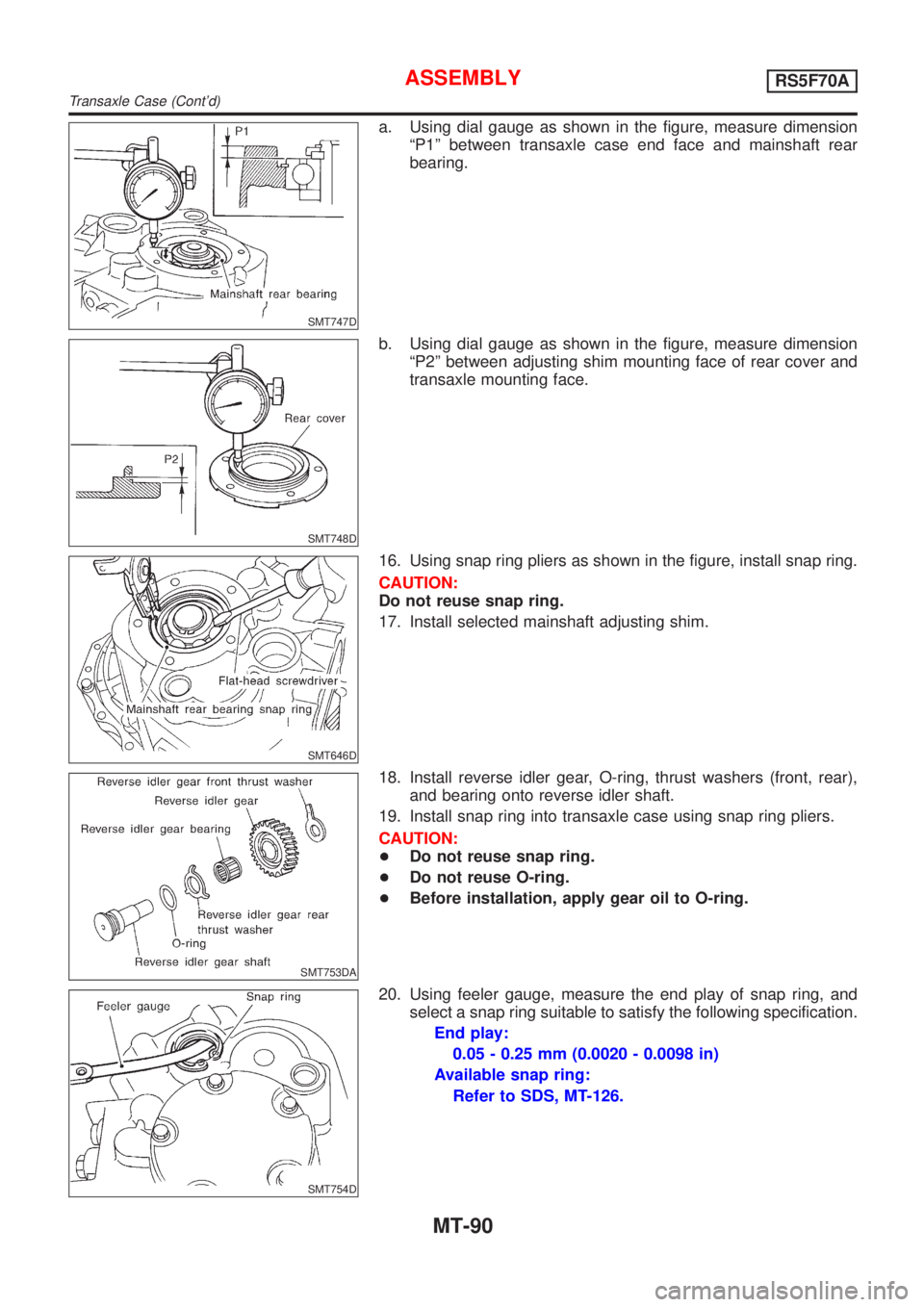
SMT747D
a. Using dial gauge as shown in the figure, measure dimension
ªP1º between transaxle case end face and mainshaft rear
bearing.
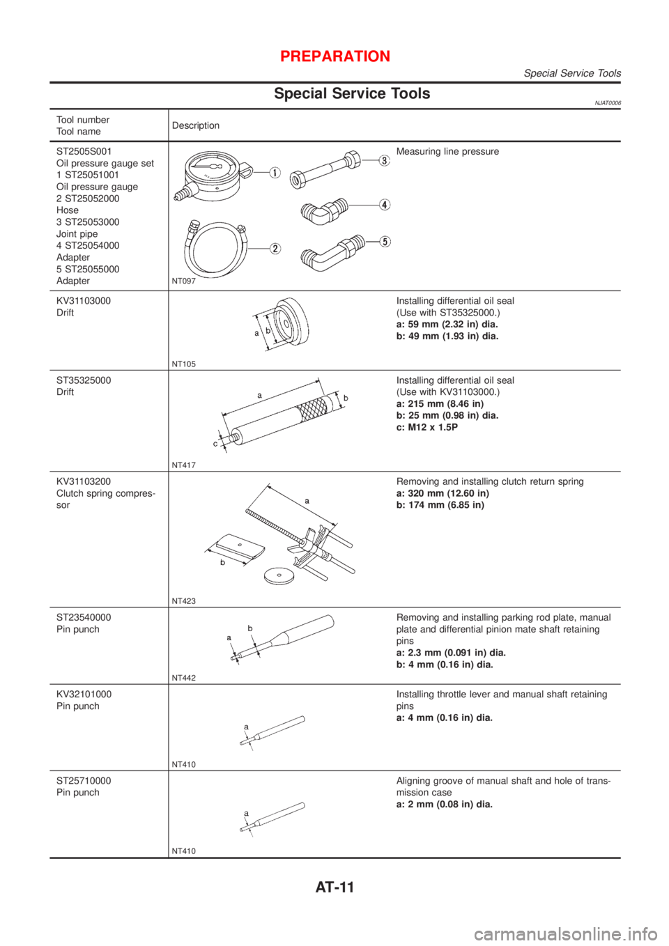
SMT748D
b. Using dial gauge as shown in the figure, measure dimension
ªP2º between adjusting shim mounting face of rear cover and
transaxle mounting face.
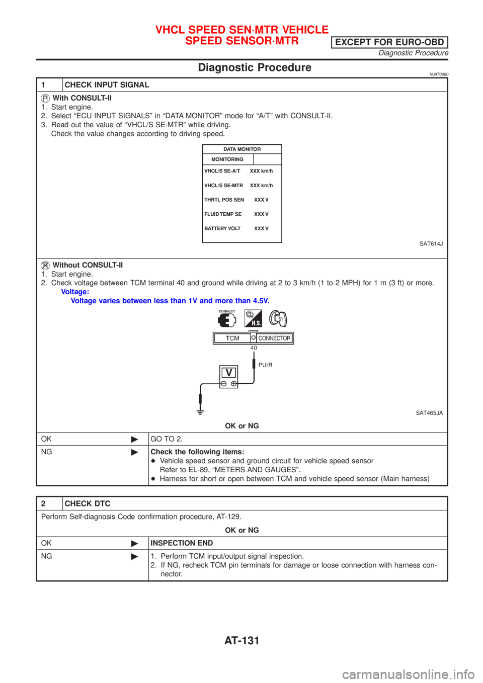
SMT646D
16. Using snap ring pliers as shown in the figure, install snap ring.
CAUTION:
Do not reuse snap ring.
17. Install selected mainshaft adjusting shim.
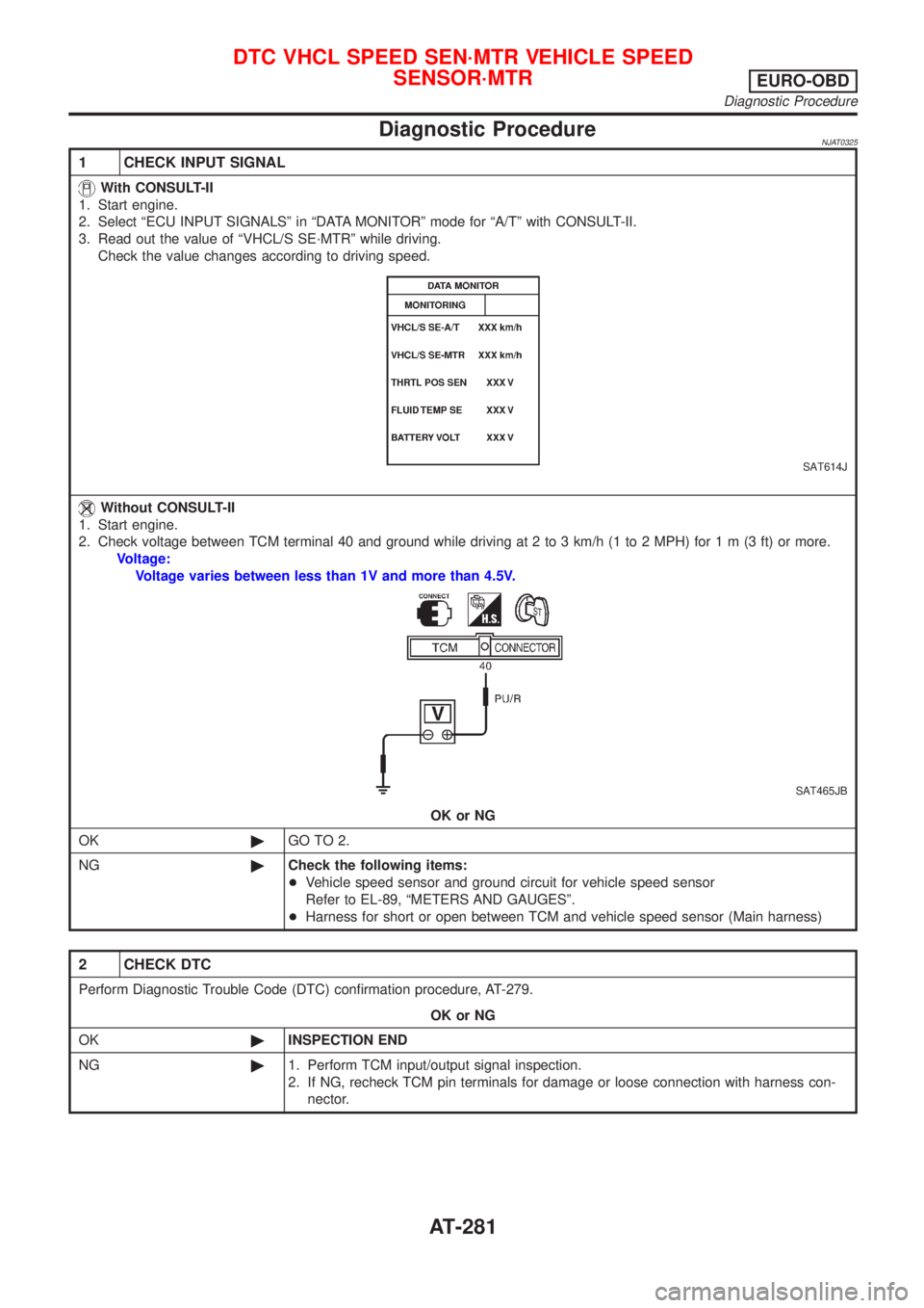
SMT753DA
18. Install reverse idler gear, O-ring, thrust washers (front, rear),
and bearing onto reverse idler shaft.
19. Install snap ring into transaxle case using snap ring pliers.
CAUTION:
+Do not reuse snap ring.
+Do not reuse O-ring.
+Before installation, apply gear oil to O-ring.
SMT754D
20. Using feeler gauge, measure the end play of snap ring, and
select a snap ring suitable to satisfy the following specification.
End play:
0.05 - 0.25 mm (0.0020 - 0.0098 in)
Available snap ring:
Refer to SDS, MT-126.
ASSEMBLYRS5F70A
Transaxle Case (Cont'd)
MT-90
Page 1197 of 2493

Special Service ToolsNJAT0006
Tool number
Tool nameDescription
ST2505S001
Oil pressure gauge set
1 ST25051001
Oil pressure gauge
2 ST25052000
Hose
3 ST25053000
Joint pipe
4 ST25054000
Adapter
5 ST25055000
Adapter
NT097
Measuring line pressure
KV31103000
Drift
NT105
Installing differential oil seal
(Use with ST35325000.)
a: 59 mm (2.32 in) dia.
b: 49 mm (1.93 in) dia.
ST35325000
Drift
NT417
Installing differential oil seal
(Use with KV31103000.)
a: 215 mm (8.46 in)
b: 25 mm (0.98 in) dia.
c: M12 x 1.5P
KV31103200
Clutch spring compres-
sor
NT423
Removing and installing clutch return spring
a: 320 mm (12.60 in)
b: 174 mm (6.85 in)
ST23540000
Pin punch
NT442
Removing and installing parking rod plate, manual
plate and differential pinion mate shaft retaining
pins
a: 2.3 mm (0.091 in) dia.
b: 4 mm (0.16 in) dia.
KV32101000
Pin punch
NT410
Installing throttle lever and manual shaft retaining
pins
a: 4 mm (0.16 in) dia.
ST25710000
Pin punch
NT410
Aligning groove of manual shaft and hole of trans-
mission case
a: 2 mm (0.08 in) dia.
PREPARATION
Special Service Tools
AT-11
Page 1268 of 2493
SAT561J
Line Pressure TestNJAT0027LINE PRESSURE TEST PORTSNJAT0027S01Location of line pressure test ports are shown in the illustration.
+Always replace pressure plugs as they are self-sealing
bolts.
SAT647B
LINE PRESSURE TEST PROCEDURENJAT0027S021. Check A/T fluid and engine oil levels. If necessary, add fluid or
oil.
2. Drive vehicle for approx. 10 minutes or until engine oil and ATF
reach operating temperature.
ATF operating temperature:
50 - 80ÉC (122 - 176ÉF)
UAT008
3. Install pressure gauge to corresponding line pressure port.
UAT008
4. Set parking brake and block wheels.
+Continue to depress brake pedal fully while line pressure
test is being performed at stall speed.
SAT493G
5. Start engine and measure line pressure at idle and stall speed.
+When measuring line pressure at stall speed, follow the
stall test procedure.
Line pressure: Refer to SDS, AT-450.
TROUBLE DIAGNOSIS Ð BASIC INSPECTION
Line Pressure Test
AT-82
Page 1317 of 2493

Diagnostic ProcedureNJAT0080
1 CHECK INPUT SIGNAL
With CONSULT-II
1. Start engine.
2. Select ªECU INPUT SIGNALSº in ªDATA MONITORº mode for ªA/Tº with CONSULT-II.
3. Read out the value of ªVHCL/S SE´MTRº while driving.
Check the value changes according to driving speed.
SAT614J
Without CONSULT-II
1. Start engine.
2. Check voltage between TCM terminal 40 and ground while driving at 2 to 3 km/h (1 to 2 MPH) for1m(3ft)ormore.
Voltage:
Voltage varies between less than 1V and more than 4.5V.
SAT465JA
OK or NG
OK©GO TO 2.
NG©Check the following items:
+Vehicle speed sensor and ground circuit for vehicle speed sensor
Refer to EL-89, ªMETERS AND GAUGESº.
+Harness for short or open between TCM and vehicle speed sensor (Main harness)
2 CHECK DTC
Perform Self-diagnosis Code confirmation procedure, AT-129.
OK or NG
OK©INSPECTION END
NG©1. Perform TCM input/output signal inspection.
2. If NG, recheck TCM pin terminals for damage or loose connection with harness con-
nector.
VHCL SPEED SEN´MTR VEHICLE
SPEED SENSOR´MTR
EXCEPT FOR EURO-OBD
Diagnostic Procedure
AT-131
Page 1467 of 2493

Diagnostic ProcedureNJAT0325
1 CHECK INPUT SIGNAL
With CONSULT-II
1. Start engine.
2. Select ªECU INPUT SIGNALSº in ªDATA MONITORº mode for ªA/Tº with CONSULT-II.
3. Read out the value of ªVHCL/S SE´MTRº while driving.
Check the value changes according to driving speed.
SAT614J
Without CONSULT-II
1. Start engine.
2. Check voltage between TCM terminal 40 and ground while driving at 2 to 3 km/h (1 to 2 MPH) for1m(3ft)ormore.
Voltage:
Voltage varies between less than 1V and more than 4.5V.
SAT465JB
OK or NG
OK©GO TO 2.
NG©Check the following items:
+Vehicle speed sensor and ground circuit for vehicle speed sensor
Refer to EL-89, ªMETERS AND GAUGESº.
+Harness for short or open between TCM and vehicle speed sensor (Main harness)
2 CHECK DTC
Perform Diagnostic Trouble Code (DTC) confirmation procedure, AT-279.
OK or NG
OK©INSPECTION END
NG©1. Perform TCM input/output signal inspection.
2. If NG, recheck TCM pin terminals for damage or loose connection with harness con-
nector.
DTC VHCL SPEED SEN´MTR VEHICLE SPEED
SENSOR´MTR
EURO-OBD
Diagnostic Procedure
AT-281
Page 1475 of 2493

2 CHECK TCM GROUND CIRCUIT
1. Turn ignition switch to ªOFFº position.
2. Disconnect TCM harness connector.
3. Check continuity between TCM terminals 25, 48 and ground.
SAT468J
Continuity should exist.
If OK, check harness for short to ground and short to power.
OK or NG
OK©GO TO 3.
NG©Repair open circuit or short to ground or short to power in harness or connectors. Refer
to ªWiring Diagram Ð AT Ð MAINº, AT-121.
3 CHECK LAMP CIRCUIT
1. Turn ignition switch to ªOFFº position.
2. Check resistance between TCM terminals 13 and 10.
Resistance: 50 - 100W
SAT469JB
3. Reinstall any part removed.
OK or NG
OK©GO TO 4.
NG©Check the following items:
+O/D OFF indicator lamp.
Refer to EL-89, ªMETERS AND GAUGESº.
+Harness and fuse for short or open between ignition switch and O/D OFF indicator
lamp (Main harness)
Refer to EL-10, ªPOWER SUPPLY ROUTINGº.
+Harness for short or open between O/D OFF indicator lamp and TCM.
TROUBLE DIAGNOSES FOR SYMPTOMS
1. O/D OFF Indicator Lamp Does Not Come On (Cont'd)
AT-289
Page 1548 of 2493
SAT047D
b. Remove front planetary carrier with low one-way clutch.
SAT048D
c. Check that low one-way clutch rotates in the direction of the
arrow and locks in the opposite direction.
d. Remove low one-way clutch from front planetary carrier by
rotating it in the direction of unlock.
SAT049D
e. Remove needle bearing from front planetary carrier.
SAT050D
f. Check front planetary carrier, low one-way clutch and needle
bearing for damage or wear.
g. Check clearance between pinion washer and planetary carrier
using feeler gauge.
Standard clearance:
0.15 - 0.70 mm (0.0059 - 0.0276 in)
Allowable limit:
0.80 mm (0.0315 in)
Replace front planetary carrier if the clearance exceeds allow-
able limit.
SAT051D
35. Remove rear planetary carrier assembly and rear sun gear
according to the following procedures.
a. Remove rear planetary carrier assembly from transmission
case.
DISASSEMBLY
AT-362
Page 1549 of 2493
SAT052D
b. Remove rear sun gear from rear planetary carrier.
SAT053D
c. Remove needle bearings from rear planetary carrier assembly.
SAT054D
d. Check rear planetary carrier, rear sun gear and needle bear-
ings for damage or wear.
e. Check clearance between pinion washer and rear planetary
carrier using feeler gauge.
Standard clearance:
0.15 - 0.70 mm (0.0059 - 0.0276 in)
Allowable limit:
0.80 mm (0.0315 in)
Replace rear planetary carrier if the clearance exceeds allow-
able limit.
SAT055D
36. Remove rear internal gear from transmission case.
SAT056D
37. Remove needle bearing from rear internal gear.
+Check needle bearing for damage or wear.
DISASSEMBLY
AT-363