Page 273 of 2493

SEM164F
AEM080
Precautions
LIQUID GASKET APPLICATION PROCEDURENJLC00391. Use a scraper to remove all traces of old liquid gasket from
mating surfaces and grooves. Also, completely clean any oil
from these areas.
2. Apply a continuous bead of liquid gasket to mating surfaces.
(Use Genuine Liquid Gasket or equivalent.)
+For oil pan, be sure liquid gasket diameter is 4.0 to 5.0 mm
(0.157 to 0.197 in).
+For areas except oil pan, be sure liquid gasket diameter is 2.0
to 3.0 mm (0.079 to 0.118 in).
3. Apply liquid gasket around the inner side of bolt holes (unless
otherwise specified).
4. Assembly should be done within 5 minutes after coating.
5. Wait at least 30 minutes before refilling engine oil and engine
coolant.
Preparation
SPECIAL SERVICE TOOLSNJLC0040
Tool number
Tool nameDescription
ST25051001
Oil pressure gauge
NT050
ST25052000
Hose
NT559
Adapting oil pressure gauge to upper oil pan
WS39930000
Tube pressure
NT052
Pressing the tube of liquid gasket
ENGINE LUBRICATION SYSTEMYD
Precautions
LC-25
Page 275 of 2493

SLC283B
JLC284B
SLC926-A
Oil Pressure CheckNJLC0042WARNING:
+Be careful not to burn yourself, as the engine and oil may
be hot.
+Oil pressure check should be done in ªNeutral positionº.
1. Check oil level.
2. Remove exhaust front tube.
3. Remove oil pressure switch.
4. Install pressure gauge.
5. Install exhaust front tube.
6. Start engine and warm it up to normal operating temperature.
7. Check oil pressure with engine running under no-load.
Engine speed
rpmApproximate discharge pressure
kPa (bar, kg/cm2, psi)
Idle speed More than 140 (1.40, 1.43, 20.3)
2,000 More than 270 (2.69, 2.75, 39.1)
4,000 More than 430 (4.29, 4.38, 62.3)
If difference is extreme, check oil passage and oil pump
for oil leaks.
8. After the inspections, install the oil pressure switch as follows.
a. Remove the old sealant adhering to the switch and engine.
b. Apply Genuine Liquid Gasket or equivalent to the thread and
tighten.
: 13 - 17 N´m (1.25 - 1.75 kg-m,9-12ft-lb)
Oil Pump
REMOVAL AND INSTALLATIONNJLC0043+When installing oil pump, apply engine oil to rotors.
Refer to EM-98, ªPrimary Timing Chainº for removal.
Reinstall all parts in the reverse order of removal.
ENGINE LUBRICATION SYSTEMYD
Lubrication Circuit (Cont'd)
LC-27
Page 276 of 2493
DISASSEMBLY AND ASSEMBLYNJLC0044
JLC285B
JLC286B
JLC355B
OIL PUMP INSPECTIONNJLC0045+Install the inner rotor and outer rotor with the punched
marks on the pump cover side.
Using a feeler gauge, straightedge and micrometers, check the
following clearances:
Unit: mm (in)
Body to outer rotor radial clearance10.114 - 0.260 (0.0045 - 0.0102)
Inner rotor to outer rotor tip clearance
2Below 0.18 (0.0071)
Body to inner rotor axial clearance30.050 - 0.090 (0.0020 - 0.0035)
Body to outer rotor axial clearance40.030 - 0.190 (0.0012 - 0.0075)
Inner rotor to brazed portion of hous-
ing clearance50.045 - 0.091 (0.0018 - 0.0036)
+If the tip clearance (2) exceeds the limit, replace rotor set.
+If body to rotor clearances (1, 3, 4, 5) exceed the limit,
replace oil pump body assembly.
ENGINE LUBRICATION SYSTEMYD
Oil Pump (Cont'd)
LC-28
Page 292 of 2493

+While filling, if coolant from engine side spills out, be sure to
reconnect the heater hose.
+Fill coolant to the level of the radiator cap at a rate of 2!(1-3/4
Imp qt)/min or lower.
(Close the air relief plugs in order starting with the location from
where the coolant began spilling out.)
CAUTION:
If the filling rate is too fast, this could lead to air being mixed
in the coolant. Be sure to fill the coolant slowly according to
the rate indicated above.
+Replace the copper washer of the air bleeding plug.
Air relief plug:
: 6.7 - 7.9 N´m (0.68 - 0.81 kg-m, 59 - 70 in-lb)
+Use genuine Nissan anti-freeze coolant or equivalent
mixed with water (distilled or demineralized).
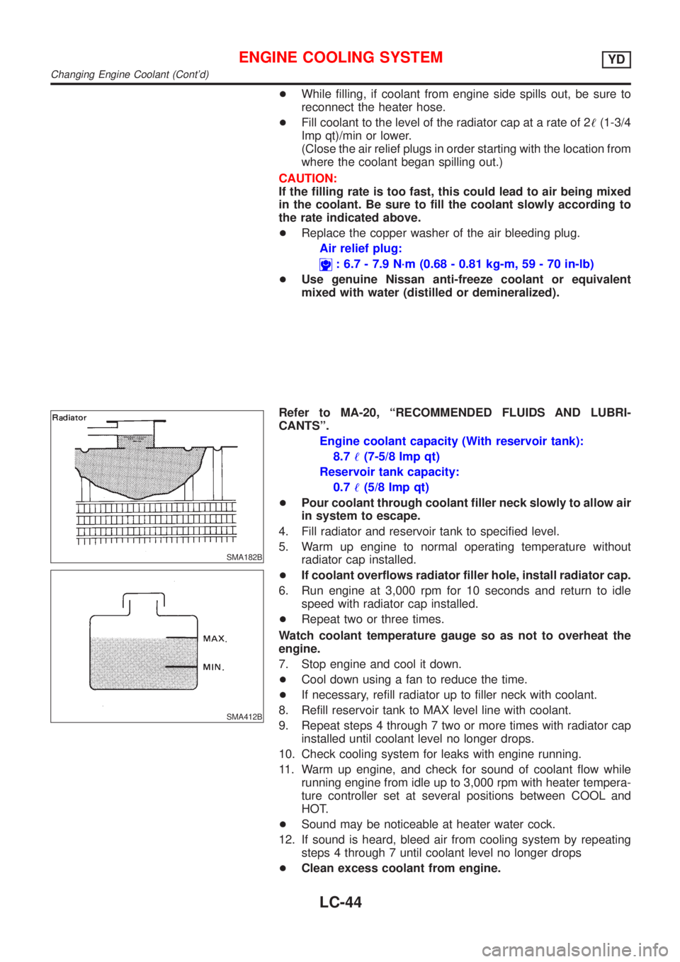
SMA182B
SMA412B
Refer to MA-20, ªRECOMMENDED FLUIDS AND LUBRI-
CANTSº.
Engine coolant capacity (With reservoir tank):
8.7!(7-5/8 Imp qt)
Reservoir tank capacity:
0.7!(5/8 Imp qt)
+Pour coolant through coolant filler neck slowly to allow air
in system to escape.
4. Fill radiator and reservoir tank to specified level.
5. Warm up engine to normal operating temperature without
radiator cap installed.
+If coolant overflows radiator filler hole, install radiator cap.
6. Run engine at 3,000 rpm for 10 seconds and return to idle
speed with radiator cap installed.
+Repeat two or three times.
Watch coolant temperature gauge so as not to overheat the
engine.
7. Stop engine and cool it down.
+Cool down using a fan to reduce the time.
+If necessary, refill radiator up to filler neck with coolant.
8. Refill reservoir tank to MAX level line with coolant.
9. Repeat steps 4 through 7 two or more times with radiator cap
installed until coolant level no longer drops.
10. Check cooling system for leaks with engine running.
11. Warm up engine, and check for sound of coolant flow while
running engine from idle up to 3,000 rpm with heater tempera-
ture controller set at several positions between COOL and
HOT.
+Sound may be noticeable at heater water cock.
12. If sound is heard, bleed air from cooling system by repeating
steps 4 through 7 until coolant level no longer drops
+Clean excess coolant from engine.
ENGINE COOLING SYSTEMYD
Changing Engine Coolant (Cont'd)
LC-44
Page 334 of 2493

SEF094Y
SEF214Y
Fuel Pressure ReleaseNJEC0024Before disconnecting fuel line, release fuel pressure from fuel
line to eliminate danger.
WITH CONSULT-IINJEC0024S011. Start engine.
2. Perform ªFUEL PRESSURE RELEASEº in ªWORK SUP-
PORTº mode with CONSULT-II.
3. After engine stalls, crank it two or three times to release all fuel
pressure.
4. Turn ignition switch OFF.
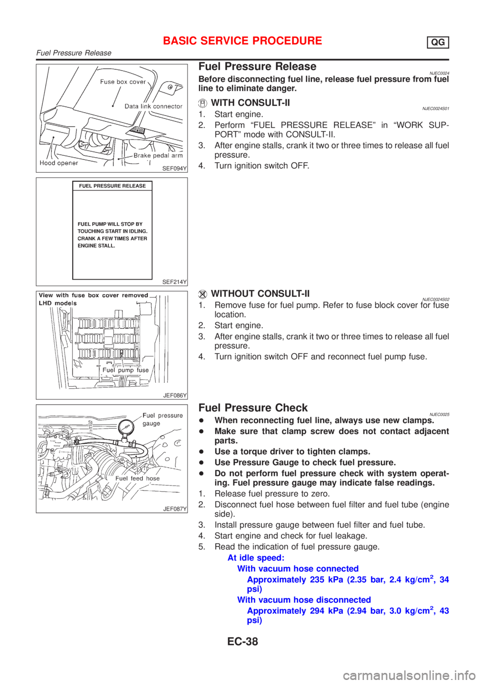
JEF086Y
WITHOUT CONSULT-IINJEC0024S021. Remove fuse for fuel pump. Refer to fuse block cover for fuse
location.
2. Start engine.
3. After engine stalls, crank it two or three times to release all fuel
pressure.
4. Turn ignition switch OFF and reconnect fuel pump fuse.
JEF087Y
Fuel Pressure CheckNJEC0025+When reconnecting fuel line, always use new clamps.
+Make sure that clamp screw does not contact adjacent
parts.
+Use a torque driver to tighten clamps.
+Use Pressure Gauge to check fuel pressure.
+Do not perform fuel pressure check with system operat-
ing. Fuel pressure gauge may indicate false readings.
1. Release fuel pressure to zero.
2. Disconnect fuel hose between fuel filter and fuel tube (engine
side).
3. Install pressure gauge between fuel filter and fuel tube.
4. Start engine and check for fuel leakage.
5. Read the indication of fuel pressure gauge.
At idle speed:
With vacuum hose connected
Approximately 235 kPa (2.35 bar, 2.4 kg/cm
2,34
psi)
With vacuum hose disconnected
Approximately 294 kPa (2.94 bar, 3.0 kg/cm
2,43
psi)
BASIC SERVICE PROCEDUREQG
Fuel Pressure Release
EC-38
Page 335 of 2493

If results are unsatisfactory, perform Fuel Pressure Regulator
Check, EC-39.
SEF718B
Fuel Pressure Regulator CheckNJEC00261. Stop engine and disconnect fuel pressure regulator vacuum
hose from intake manifold.
2. Plug intake manifold with a rubber cap.
3. Connect variable vacuum source to fuel pressure regulator.
4. Start engine and read indication of fuel pressure gauge as
vacuum is changed.
Fuel pressure should decrease as vacuum increases. If results
are unsatisfactory, replace fuel pressure regulator.
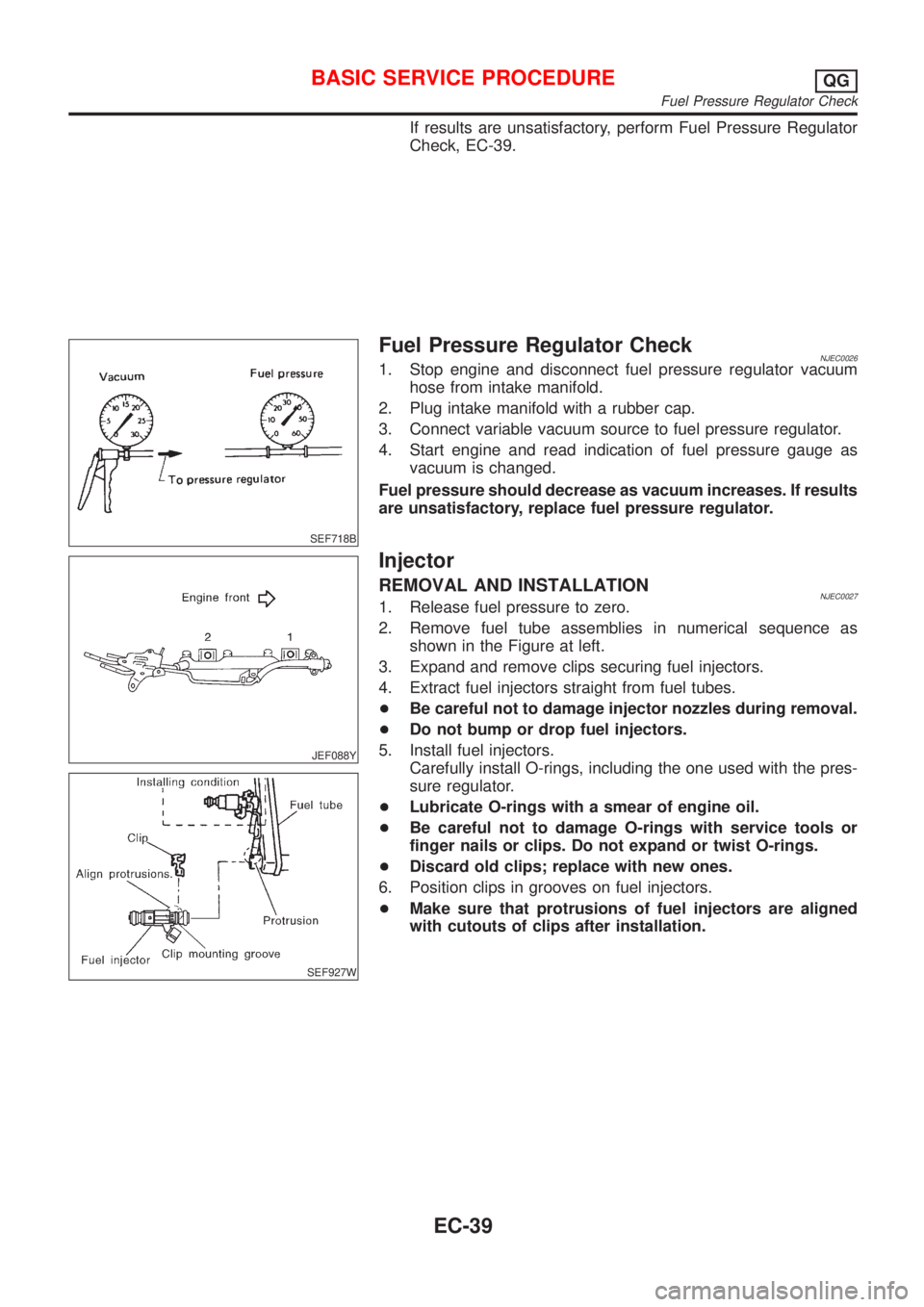
JEF088Y
SEF927W
Injector
REMOVAL AND INSTALLATIONNJEC00271. Release fuel pressure to zero.
2. Remove fuel tube assemblies in numerical sequence as
shown in the Figure at left.
3. Expand and remove clips securing fuel injectors.
4. Extract fuel injectors straight from fuel tubes.
+Be careful not to damage injector nozzles during removal.
+Do not bump or drop fuel injectors.
5. Install fuel injectors.
Carefully install O-rings, including the one used with the pres-
sure regulator.
+Lubricate O-rings with a smear of engine oil.
+Be careful not to damage O-rings with service tools or
finger nails or clips. Do not expand or twist O-rings.
+Discard old clips; replace with new ones.
6. Position clips in grooves on fuel injectors.
+Make sure that protrusions of fuel injectors are aligned
with cutouts of clips after installation.
BASIC SERVICE PROCEDUREQG
Fuel Pressure Regulator Check
EC-39
Page 338 of 2493
SEF933W
SEF284G
+Method B
a) Remove No. 1 ignition coil.
b) Connect No. 1 ignition coil and No. 1 spark plug with suitable
high-tension wire as shown, and attach timing light clamp to
this wire.
c) Check ignition timing.
SEF166Y
PreparationNJEC0592+Make sure that the following parts are in good order.
a)Battery
b)Ignition system
c)Engine oil and coolant levels
d)Fuses
e)ECM harness connector
f)Vacuum hoses
g)Air intake system
(Oil filler cap, oil level gauge, etc.)
BASIC SERVICE PROCEDUREQG
How to Check Idle Speed and Ignition Timing (Cont'd)
EC-42
Page 341 of 2493
Inspection ProcedureNJEC0593
1 INSPECTION START
1. Visually check the following:
+Air cleaner clogging
+Hoses and ducts for leaks
+EGR valve operation
+Electrical connectors
+Gasket
+Throttle valve and throttle position sensor operation
2. Start engine and warm it up until engine coolant temperature indicator points to the middle of gauge.
Ensure engine stays below 1,000 rpm.
SEF090Y
3. Open engine hood and run engine at about 2,000 rpm for about 2 minutes under no-load.
SEF977U
4. Make sure that no DTC is displayed with CONSULT-II or GST.
OK or NG
OK©GO TO 3.
NG©GO TO 2.
2 REPAIR OR REPLACE
Repair or replace components as necessary according to corresponding ªDiagnostic Procedureº.
©GO TO 3.
BASIC SERVICE PROCEDUREQG
Inspection Procedure
EC-45