Page 221 of 2493
JEM200G
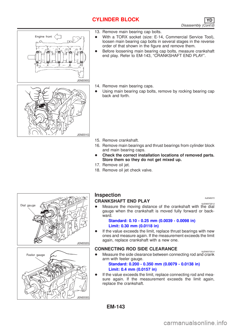
13. Remove main bearing cap bolts.
+With a TORX socket (size: E-14, Commercial Service Tool),
loosen main bearing cap bolts in several stages in the reverse
order of that shown in the figure and remove them.
+Before loosening main bearing cap bolts, measure crankshaft
end play. Refer to EM-143, ªCRANKSHAFT END PLAYº.
JEM201G
14. Remove main bearing caps.
+Using main bearing cap bolts, remove by rocking bearing cap
back and forth.
15. Remove crankshaft.
16. Remove main bearings and thrust bearings from cylinder block
and main bearing caps.
+Check the correct installation locations of removed parts.
Store them so they do not get mixed up.
17. Remove oil jet.
18. Remove oil jet check valve.
JEM202G
InspectionNJEM0073CRANKSHAFT END PLAYNJEM0073S13+Measure the moving distance of the crankshaft with the dial
gauge when the crankshaft is moved fully forward or back-
ward.
Standard: 0.10 - 0.25 mm (0.0039 - 0.0098 in)
Limit: 0.30 mm (0.0118 in)
+If the value exceeds the limit, replace thrust bearings with new
ones and measure again. If the measurement exceeds the limit
again, replace crankshaft with a new one.
JEM203G
CONNECTING ROD SIDE CLEARANCENJEM0073S14+Measure the side clearance between connecting rod and crank
arm with feeler gauge.
Standard: 0.200 - 0.350 mm (0.0079 - 0.0138 in)
Limit: 0.4 mm (0.0157 in)
+If the value exceeds the limit, replace connecting rod and mea-
sure again. If the measurement exceeds the limit again,
replace the crankshaft.
CYLINDER BLOCKYD
Disassembly (Cont'd)
EM-143
Page 223 of 2493
SEM599A
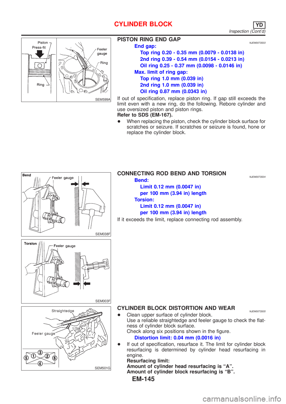
PISTON RING END GAPNJEM0073S03End gap:
Top ring 0.20 - 0.35 mm (0.0079 - 0.0138 in)
2nd ring 0.39 - 0.54 mm (0.0154 - 0.0213 in)
Oil ring 0.25 - 0.37 mm (0.0098 - 0.0146 in)
Max. limit of ring gap:
Top ring 1.0 mm (0.039 in)
2nd ring 1.0 mm (0.039 in)
Oil ring 0.87 mm (0.0343 in)
If out of specification, replace piston ring. If gap still exceeds the
limit even with a new ring, do the following. Rebore cylinder and
use oversized piston and piston rings.
Refer to SDS (EM-167).
+When replacing the piston, check the cylinder block surface for
scratches or seizure. If scratches or seizure is found, hone or
replace the cylinder block.
SEM038F
SEM003F
CONNECTING ROD BEND AND TORSIONNJEM0073S04Bend:
Limit 0.12 mm (0.0047 in)
per 100 mm (3.94 in) length
Torsion:
Limit 0.12 mm (0.0047 in)
per 100 mm (3.94 in) length
If it exceeds the limit, replace connecting rod assembly.
SEM501G
CYLINDER BLOCK DISTORTION AND WEARNJEM0073S05+Clean upper surface of cylinder block.
Use a reliable straightedge and feeler gauge to check the flat-
ness of cylinder block surface.
Check along six positions shown in the figure.
Distortion limit: 0.04 mm (0.0016 in)
+If out of specification, resurface it. The limit for cylinder block
resurfacing is determined by cylinder head resurfacing in
engine.
Resurfacing limit:
Amount of cylinder head resurfacing is ªAº.
Amount of cylinder block resurfacing is ªBº.
CYLINDER BLOCKYD
Inspection (Cont'd)
EM-145
Page 224 of 2493
The maximum limit is as follows:
A + B = 0.07mm (0.0028 in)
Nominal cylinder block height from crankshaft center:
252.95 - 253.05 mm (9.9586 - 9.9626 in)
+If necessary, replace cylinder block.
JEM206G
JEM207G
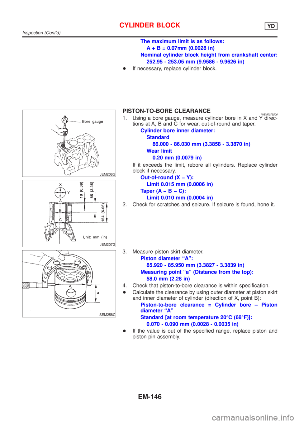
PISTON-TO-BORE CLEARANCENJEM0073S061. Using a bore gauge, measure cylinder bore in X and Y direc-
tions at A, B and C for wear, out-of-round and taper.
Cylinder bore inner diameter:
Standard
86.000 - 86.030 mm (3.3858 - 3.3870 in)
Wear limit
0.20 mm (0.0079 in)
If it exceeds the limit, rebore all cylinders. Replace cylinder
block if necessary.
Out-of-round (X þ Y):
Limit 0.015 mm (0.0006 in)
Taper (AþBþC):
Limit 0.010 mm (0.0004 in)
2. Check for scratches and seizure. If seizure is found, hone it.
SEM258C
3. Measure piston skirt diameter.
Piston diameter ªAº:
85.920 - 85.950 mm (3.3827 - 3.3839 in)
Measuring point ªaº (Distance from the top):
58.0 mm (2.28 in)
4. Check that piston-to-bore clearance is within specification.
+Calculate the clearance by using outer diameter at piston skirt
and inner diameter of cylinder (direction of X, point B):
Piston-to-bore clearance = Cylinder bore ± Piston
diameter ªAº
Standard [at room temperature 20ÉC (68ÉF)]:
0.070 - 0.090 mm (0.0028 - 0.0035 in)
+If the value is out of the specified range, replace piston and
piston pin assembly.
CYLINDER BLOCKYD
Inspection (Cont'd)
EM-146
Page 226 of 2493
SEM316A
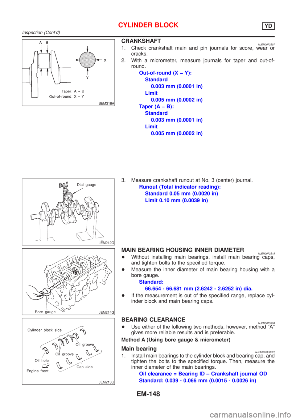
CRANKSHAFTNJEM0073S071. Check crankshaft main and pin journals for score, wear or
cracks.
2. With a micrometer, measure journals for taper and out-of-
round.
Out-of-round (X þ Y):
Standard
0.003 mm (0.0001 in)
Limit
0.005 mm (0.0002 in)
Taper (A þ B):
Standard
0.003 mm (0.0001 in)
Limit
0.005 mm (0.0002 in)
JEM212G
3. Measure crankshaft runout at No. 3 (center) journal.
Runout (Total indicator reading):
Standard 0.05 mm (0.0020 in)
Limit 0.10 mm (0.0039 in)
JEM214G
MAIN BEARING HOUSING INNER DIAMETERNJEM0073S15+Without installing main bearings, install main bearing caps,
and tighten bolts to the specified torque.
+Measure the inner diameter of main bearing housing with a
bore gauge.
Standard:
66.654 - 66.681 mm (2.6242 - 2.6252 in) dia.
+If the measurement is out of the specified range, replace cyl-
inder block and main bearing caps.
JEM213G
BEARING CLEARANCENJEM0073S08+Use either of the following two methods, however, method ªAº
gives more reliable results and is preferable.
Method A (Using bore gauge & micrometer)
Main bearingNJEM0073S08011. Install main bearings to the cylinder block and bearing cap, and
tighten the bolts to the specified torque. Then, measure the
inner diameter of the main bearings.
Oil clearance = Bearing ID ± Crankshaft journal OD
Standard: 0.039 - 0.066 mm (0.0015 - 0.0026 in)
CYLINDER BLOCKYD
Inspection (Cont'd)
EM-148
Page 251 of 2493
SEM164F
AEM080
Precautions
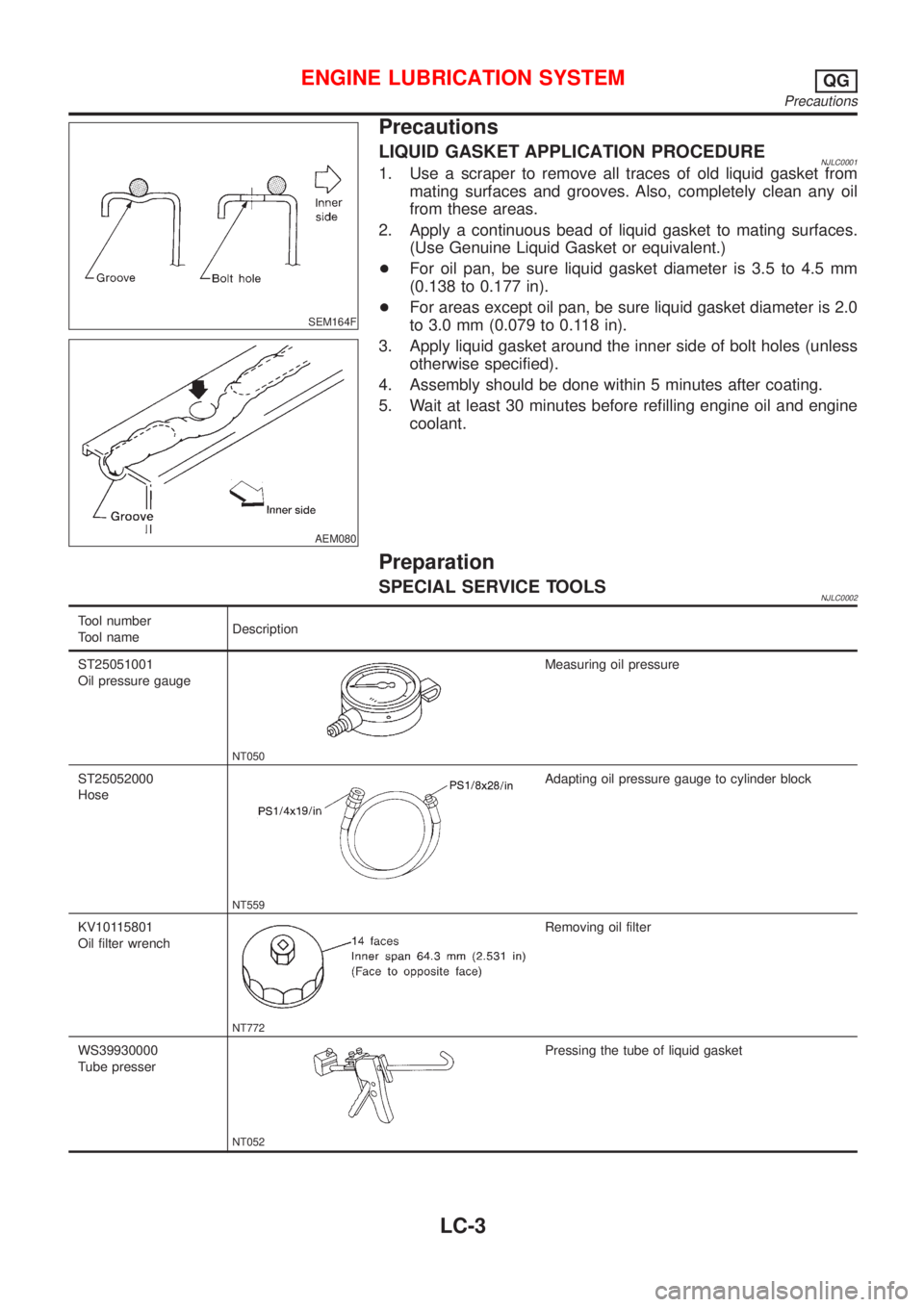
LIQUID GASKET APPLICATION PROCEDURENJLC00011. Use a scraper to remove all traces of old liquid gasket from
mating surfaces and grooves. Also, completely clean any oil
from these areas.
2. Apply a continuous bead of liquid gasket to mating surfaces.
(Use Genuine Liquid Gasket or equivalent.)
+For oil pan, be sure liquid gasket diameter is 3.5 to 4.5 mm
(0.138 to 0.177 in).
+For areas except oil pan, be sure liquid gasket diameter is 2.0
to 3.0 mm (0.079 to 0.118 in).
3. Apply liquid gasket around the inner side of bolt holes (unless
otherwise specified).
4. Assembly should be done within 5 minutes after coating.
5. Wait at least 30 minutes before refilling engine oil and engine
coolant.
Preparation
SPECIAL SERVICE TOOLSNJLC0002
Tool number
Tool nameDescription
ST25051001
Oil pressure gauge
NT050
Measuring oil pressure
ST25052000
Hose
NT559
Adapting oil pressure gauge to cylinder block
KV10115801
Oil filter wrench
NT772
Removing oil filter
WS39930000
Tube presser
NT052
Pressing the tube of liquid gasket
ENGINE LUBRICATION SYSTEMQG
Precautions
LC-3
Page 253 of 2493
SEM853F
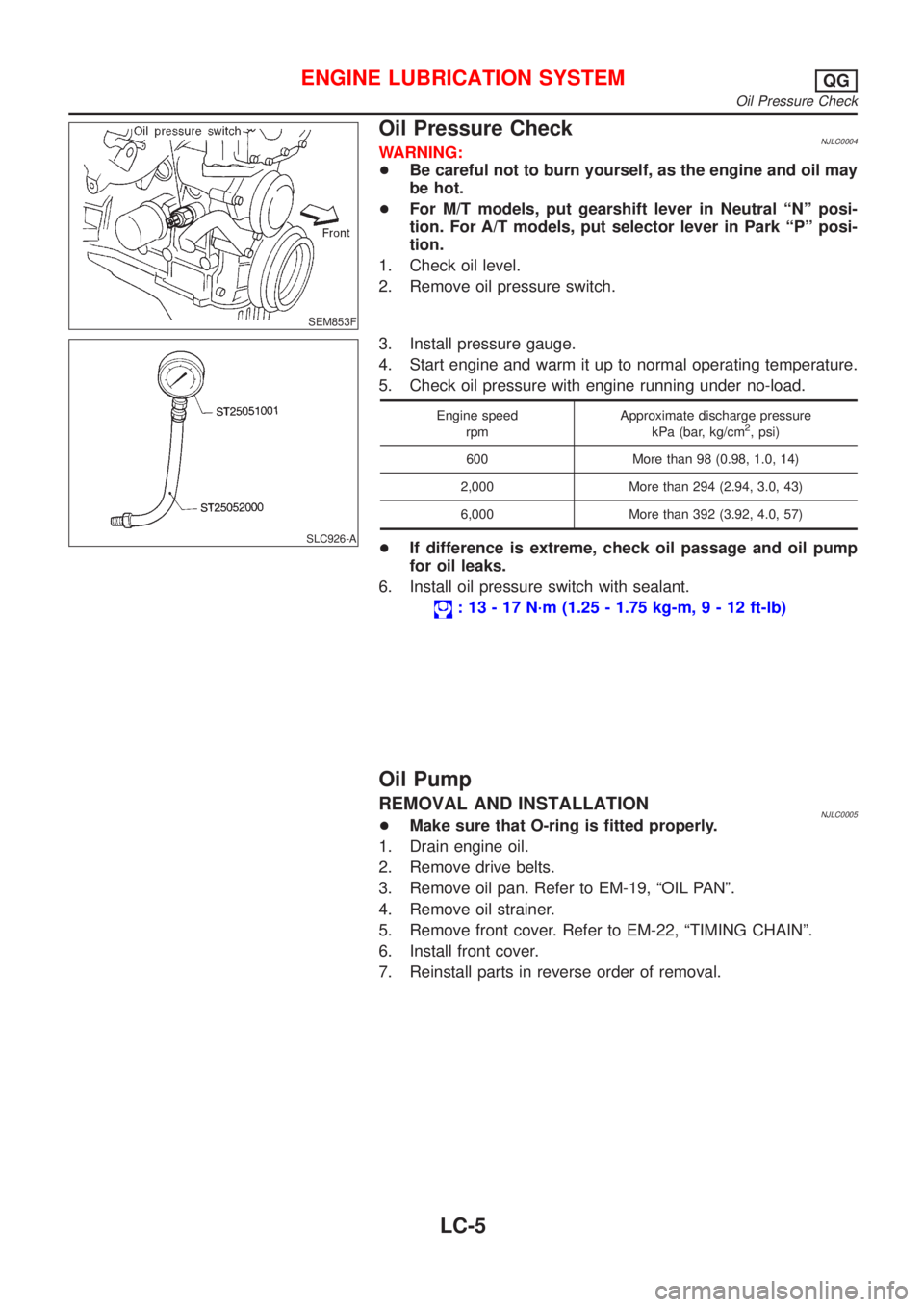
Oil Pressure CheckNJLC0004WARNING:
+Be careful not to burn yourself, as the engine and oil may
be hot.
+For M/T models, put gearshift lever in Neutral ªNº posi-
tion. For A/T models, put selector lever in Park ªPº posi-
tion.
1. Check oil level.
2. Remove oil pressure switch.
SLC926-A
3. Install pressure gauge.
4. Start engine and warm it up to normal operating temperature.
5. Check oil pressure with engine running under no-load.
Engine speed
rpmApproximate discharge pressure
kPa (bar, kg/cm2, psi)
600 More than 98 (0.98, 1.0, 14)
2,000 More than 294 (2.94, 3.0, 43)
6,000 More than 392 (3.92, 4.0, 57)
+If difference is extreme, check oil passage and oil pump
for oil leaks.
6. Install oil pressure switch with sealant.
: 13 - 17 N´m (1.25 - 1.75 kg-m,9-12ft-lb)
Oil Pump
REMOVAL AND INSTALLATIONNJLC0005+Make sure that O-ring is fitted properly.
1. Drain engine oil.
2. Remove drive belts.
3. Remove oil pan. Refer to EM-19, ªOIL PANº.
4. Remove oil strainer.
5. Remove front cover. Refer to EM-22, ªTIMING CHAINº.
6. Install front cover.
7. Reinstall parts in reverse order of removal.
ENGINE LUBRICATION SYSTEMQG
Oil Pressure Check
LC-5
Page 255 of 2493
SEM855F
SEM856F
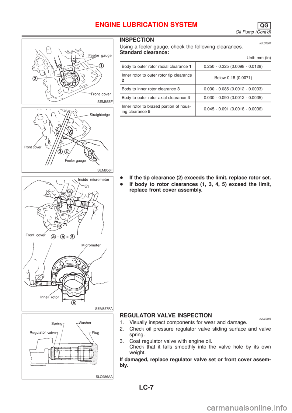
INSPECTIONNJLC0007Using a feeler gauge, check the following clearances.
Standard clearance:
Unit: mm (in)
Body to outer rotor radial clearance10.250 - 0.325 (0.0098 - 0.0128)
Inner rotor to outer rotor tip clearance
2Below 0.18 (0.0071)
Body to inner rotor clearance30.030 - 0.085 (0.0012 - 0.0033)
Body to outer rotor axial clearance40.030 - 0.090 (0.0012 - 0.0035)
Inner rotor to brazed portion of hous-
ing clearance50.045 - 0.091 (0.0018 - 0.0036)
SEM857FA
+If the tip clearance (2) exceeds the limit, replace rotor set.
+If body to rotor clearances (1, 3, 4, 5) exceed the limit,
replace front cover assembly.
SLC986AA
REGULATOR VALVE INSPECTIONNJLC00081. Visually inspect components for wear and damage.
2. Check oil pressure regulator valve sliding surface and valve
spring.
3. Coat regulator valve with engine oil.
Check that it falls smoothly into the valve hole by its own
weight.
If damaged, replace regulator valve set or front cover assem-
bly.
ENGINE LUBRICATION SYSTEMQG
Oil Pump (Cont'd)
LC-7
Page 267 of 2493

SMA182B
SMA412B
Refer to MA-20, ªRECOMMENDED FLUIDS AND LUBRI-
CANTSº.
Coolant capacity (With reservoir tank):
Unit:!(Imp qt)
M/T 6.7 (5-7/8)
A/TFor Sedan 6.6 (5-7/8)
For Hatchback 6.7 (5-7/8)
Reservoir tank capacity:
0.7!(5/8 Imp qt)
+Pour coolant through coolant filler neck slowly to allow air
in system to escape.
3. Fill radiator and reservoir tank to specified level.
4. Warm up engine to normal operating temperature without
radiator cap installed.
+If coolant overflows radiator filler hole, install filler cap.
5. Run engine at 2,500 rpm for 10 seconds and return to idle
speed with radiator cap installed.
+Repeat two or three times.
Watch coolant temperature gauge so as not to overheat the
engine.
6. Stop engine and cool it down.
+Cool down using a fan to reduce the time.
+If necessary, refill radiator up to filler neck with coolant.
7. Refill reservoir tank to MAX level line with coolant.
8. Repeat steps 4 through 7 two or more times with radiator cap
installed until coolant level no longer drops.
9. Check cooling system for leaks with engine running.
10. Warm up engine, and check for sound of coolant flow while
running engine from idle up to 3,000 rpm with heater tempera-
ture controller set at several positions between COOL and
HOT.
+Sound may be noticeable at heater water cock.
11. If sound is heard, bleed air from cooling system by repeating
steps 4 through 7 until coolant level no longer drops
+Clean excess coolant from engine.
Ð FLUSHING COOLING SYSTEM ÐNJLC0037S031. Open air relief plug.
2. Fill radiator with water until water spills from the air relief hole,
then close air relief plug. Fill radiator and reservoir tank with
water and reinstall radiator cap.
3. Run engine and warm it up to normal operating temperature.
4. Rev engine two or three times under no-load.
5. Stop engine and wait until it cools down.
6. Drain water.
7. Repeat steps 1 through 6 until clear water begins to drain from
radiator.
ENGINE COOLING SYSTEMQG
Changing Engine Coolant (Cont'd)
LC-19