Page 191 of 2493
CAUTION:
Do not disassemble or adjust the turbocharger body.
AssemblyNJEM0103S0102When a stud bolt is pulled out, tighten it to the following torque:
: 24 - 27 N´m (2.4 - 2.8 kg-m, 18 - 20 ft-lb)
JEM267G
InspectionNJEM0104EXHAUST MANIFOLDNJEM0104S01Check the distortion on the mounting surface in the six directions
using a straightedge and a feeler gauge.
Limit: 0.3 mm (0.012 in)
TURBOCHARGERNJEM0104S02
SEM269G
CAUTION:
When the compressor wheel, turbine wheel, or rotor shaft is
damaged, remove all the fragments and foreign matter left in
the following passages in order to prevent a secondary failure:
Suction side: Between turbocharger and air cleaner
Exhaust side: Between turbocharger and catalytic con-
verter
EXHAUST MANIFOLD, TURBOCHARGERYD
Disassembly and Assembly (Cont'd)
EM-113
Page 192 of 2493
SEM270G
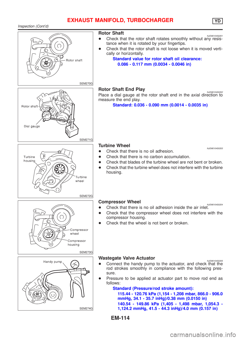
Rotor ShaftNJEM0104S0201+Check that the rotor shaft rotates smoothly without any resis-
tance when it is rotated by your fingertips.
+Check that the rotor shaft is not loose when it is moved verti-
cally or horizontally.
Standard value for rotor shaft oil clearance:
0.086 - 0.117 mm (0.0034 - 0.0046 in)
SEM271G
Rotor Shaft End PlayNJEM0104S0202Place a dial gauge at the rotor shaft end in the axial direction to
measure the end play.
Standard: 0.036 - 0.090 mm (0.0014 - 0.0035 in)
SEM272G
Turbine WheelNJEM0104S0203+Check that there is no oil adhesion.
+Check that there is no carbon accumulation.
+Check that blades of the turbine wheel are not bent or broken.
+Check that the turbine wheel does not interfere with the turbine
housing.
SEM273G
Compressor WheelNJEM0104S0204+Check that there is no oil adhesion inside the air inlet.
+Check that the compressor wheel does not interfere with the
compressor housing.
+Check that the wheel is not bent or broken.
SEM274G
Wastegate Valve ActuatorNJEM0104S0205+Connect the handy pump to the actuator, and check that the
rod strokes smoothly in compliance with the following pres-
sure.
+Pressure to be applied at actuator part to move rod end as
follows:
Standard (Pressure/rod stroke amount):
115.44 - 120.76 kPa (1,154 - 1,208 mbar, 866.0 - 906.0
mmHg, 34.1 - 35.7 inHg)/0.38 mm (0.0150 in)
140.54 - 149.86 kPa (1,405 - 1,498 mbar, 1,054.3 -
1,124.2 mmHg, 41.5 - 44.3 inHg)/4.0 mm (0.157 in)
EXHAUST MANIFOLD, TURBOCHARGERYD
Inspection (Cont'd)
EM-114
Page 199 of 2493

JEM152G
+For the locations and arrangement of intake and exhaust
valves, refer to the figure.
JEM153G
5. Remove valve oil seals.
+Use a valve oil seal puller (SST) for removal.
6. Remove valve spring seats.
7. When removing valve seats, check valve seat contact. Refer
to EM-125.
8. Before removing valve guides, check valve guide clearance.
Refer to EM-123, ªVALVE GUIDE CLEARANCEº.
9. Remove glow plugs.
+To avoid damage, glow plugs should be removed only
when required.
+Handle with care to avoid applying shock. (When dropped
from approx. 100 mm (3.94 in) or higher, always replace
with a new one.)
SEM496G
InspectionNJEM0065CYLINDER HEAD DISTORTIONNJEM0065S01Clean surface of cylinder head.
Use a reliable straightedge and feeler gauge to check the flatness
of cylinder head surface.
Check along six positions shown in the figure.
Head surface flatness: Limit 0.04 mm (0.0016 in)
If beyond the specified limit, resurface or replace it.
The limit for cylinder head resurfacing is determined by the
cylinder block resurfacing.
Resurfacing limit:
Amount of cylinder head resurfacing is ªAº.
Amount of cylinder block resurfacing is ªBº.
The maximum limit: A+ B = 0.07 mm (0.0028 in)
After resurfacing cylinder head, check that camshaft rotates freely
by hand. If resistance is felt, cylinder head must be replaced.
Nominal cylinder head height:
153.9 - 154.1 mm (6.059 - 6.067 in)
CYLINDER HEADYD
Disassembly (Cont'd)
EM-121
Page 200 of 2493
CAMSHAFT VISUAL CHECKNJEM0065S02Check camshaft for scratches, seizure and wear.
JEM161G
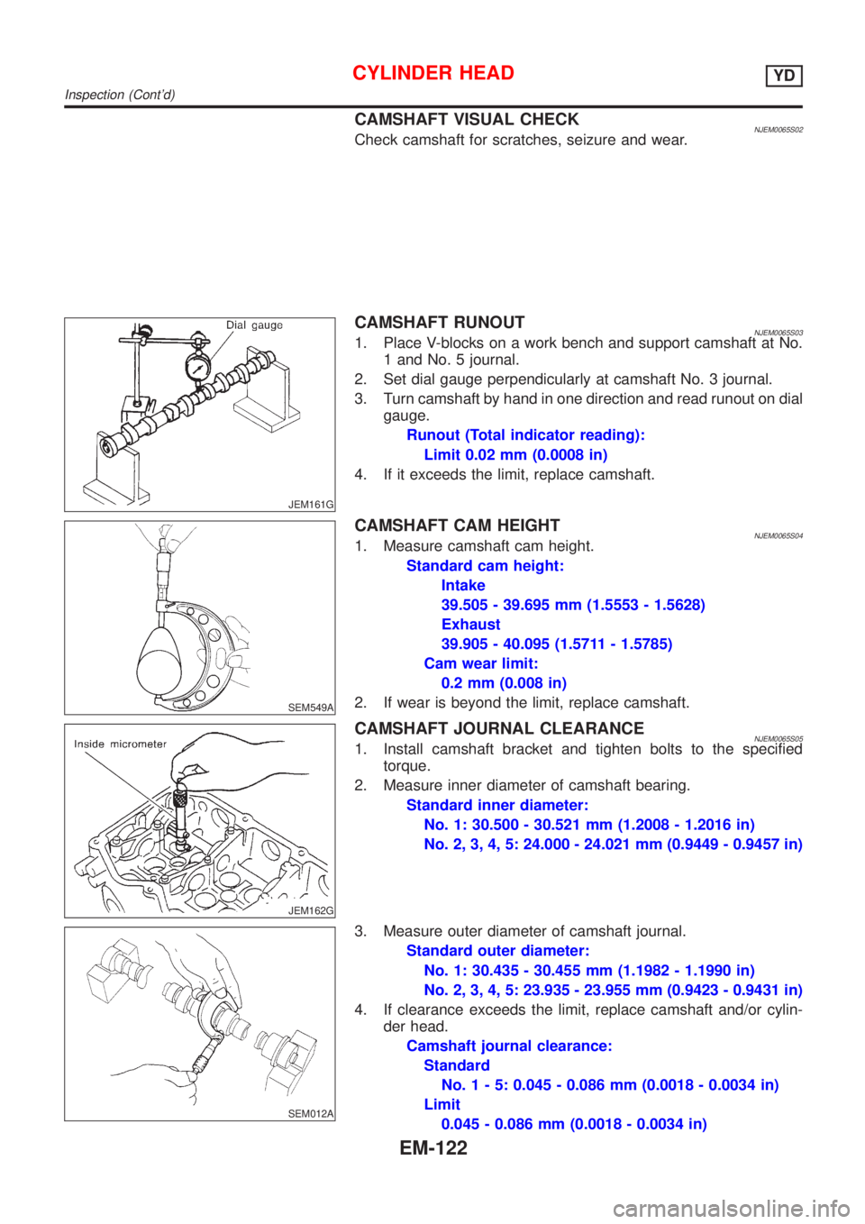
CAMSHAFT RUNOUTNJEM0065S031. Place V-blocks on a work bench and support camshaft at No.
1 and No. 5 journal.
2. Set dial gauge perpendicularly at camshaft No. 3 journal.
3. Turn camshaft by hand in one direction and read runout on dial
gauge.
Runout (Total indicator reading):
Limit 0.02 mm (0.0008 in)
4. If it exceeds the limit, replace camshaft.
SEM549A
CAMSHAFT CAM HEIGHTNJEM0065S041. Measure camshaft cam height.
Standard cam height:
Intake
39.505 - 39.695 mm (1.5553 - 1.5628)
Exhaust
39.905 - 40.095 (1.5711 - 1.5785)
Cam wear limit:
0.2 mm (0.008 in)
2. If wear is beyond the limit, replace camshaft.
JEM162G
CAMSHAFT JOURNAL CLEARANCENJEM0065S051. Install camshaft bracket and tighten bolts to the specified
torque.
2. Measure inner diameter of camshaft bearing.
Standard inner diameter:
No. 1: 30.500 - 30.521 mm (1.2008 - 1.2016 in)
No. 2, 3, 4, 5: 24.000 - 24.021 mm (0.9449 - 0.9457 in)
SEM012A
3. Measure outer diameter of camshaft journal.
Standard outer diameter:
No. 1: 30.435 - 30.455 mm (1.1982 - 1.1990 in)
No. 2, 3, 4, 5: 23.935 - 23.955 mm (0.9423 - 0.9431 in)
4. If clearance exceeds the limit, replace camshaft and/or cylin-
der head.
Camshaft journal clearance:
Standard
No.1-5:0.045 - 0.086 mm (0.0018 - 0.0034 in)
Limit
0.045 - 0.086 mm (0.0018 - 0.0034 in)
CYLINDER HEADYD
Inspection (Cont'd)
EM-122
Page 201 of 2493
JEM163G
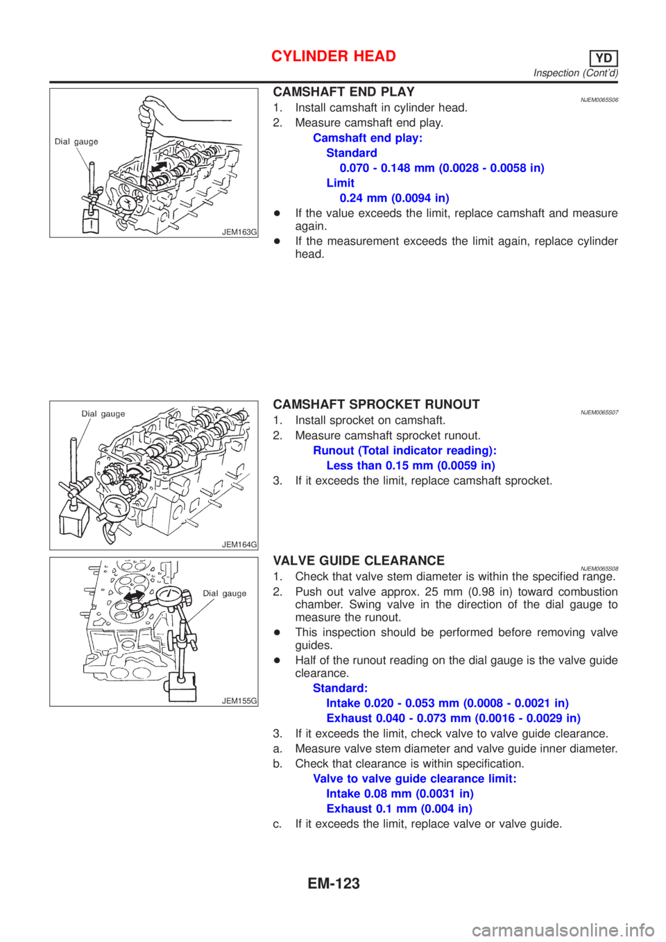
CAMSHAFT END PLAYNJEM0065S061. Install camshaft in cylinder head.
2. Measure camshaft end play.
Camshaft end play:
Standard
0.070 - 0.148 mm (0.0028 - 0.0058 in)
Limit
0.24 mm (0.0094 in)
+If the value exceeds the limit, replace camshaft and measure
again.
+If the measurement exceeds the limit again, replace cylinder
head.
JEM164G
CAMSHAFT SPROCKET RUNOUTNJEM0065S071. Install sprocket on camshaft.
2. Measure camshaft sprocket runout.
Runout (Total indicator reading):
Less than 0.15 mm (0.0059 in)
3. If it exceeds the limit, replace camshaft sprocket.
JEM155G
VALVE GUIDE CLEARANCENJEM0065S081. Check that valve stem diameter is within the specified range.
2. Push out valve approx. 25 mm (0.98 in) toward combustion
chamber. Swing valve in the direction of the dial gauge to
measure the runout.
+This inspection should be performed before removing valve
guides.
+Half of the runout reading on the dial gauge is the valve guide
clearance.
Standard:
Intake 0.020 - 0.053 mm (0.0008 - 0.0021 in)
Exhaust 0.040 - 0.073 mm (0.0016 - 0.0029 in)
3. If it exceeds the limit, check valve to valve guide clearance.
a. Measure valve stem diameter and valve guide inner diameter.
b. Check that clearance is within specification.
Valve to valve guide clearance limit:
Intake 0.08 mm (0.0031 in)
Exhaust 0.1 mm (0.004 in)
c. If it exceeds the limit, replace valve or valve guide.
CYLINDER HEADYD
Inspection (Cont'd)
EM-123
Page 204 of 2493

JEM158G
SEM301G
3. Heat cylinder head to 110 to 120ÉC (230 to 248ÉF) by soaking
in heated oil.
4. Sufficiently cool valve seat with dry ice. Force fit valve seat into
cylinder head.
WARNING:
Do not touch cold valve seat with your bare hands.
5. Cut or grind valve seat using suitable tool to the specified
dimensions as shown in SDS (EM-163).
CAUTION:
Use the valve seat cutter properly. Securely gripping the cut-
ter handle with both hands, press the cutter down onto the
entire circumference of the contacting surface and finish cut-
ting at one time. Improper pressing of the cutter or cutting in
several steps may result in staged surface on the valve seat.
6. After cutting, lap valve seat with abrasive compound.
7. Check valve seating condition. Refer to EM-125, ªValve Seatsº.
JEM253G
8. Use a depth gauge to measure the distance between the
mounting surface of the cylinder head spring seat and the
valve stem end. If the distance is shorter than specified, repeat
step 5 above to adjust it. If it is longer, replace the valve seat
with a new one.
Valve seat resurface limit ªLº:
Intake 36.53 - 36.98 mm (1.4382 - 1.4559 in)
Exhaust 36.53 - 37.01 mm (1.4382 - 1.4571 in)
CYLINDER HEADYD
Inspection (Cont'd)
EM-126
Page 207 of 2493
Installation=NJEM0067+Before installation, remove old liquid gasket from mating
surface of all liquid gasket applied parts.
SEM505G
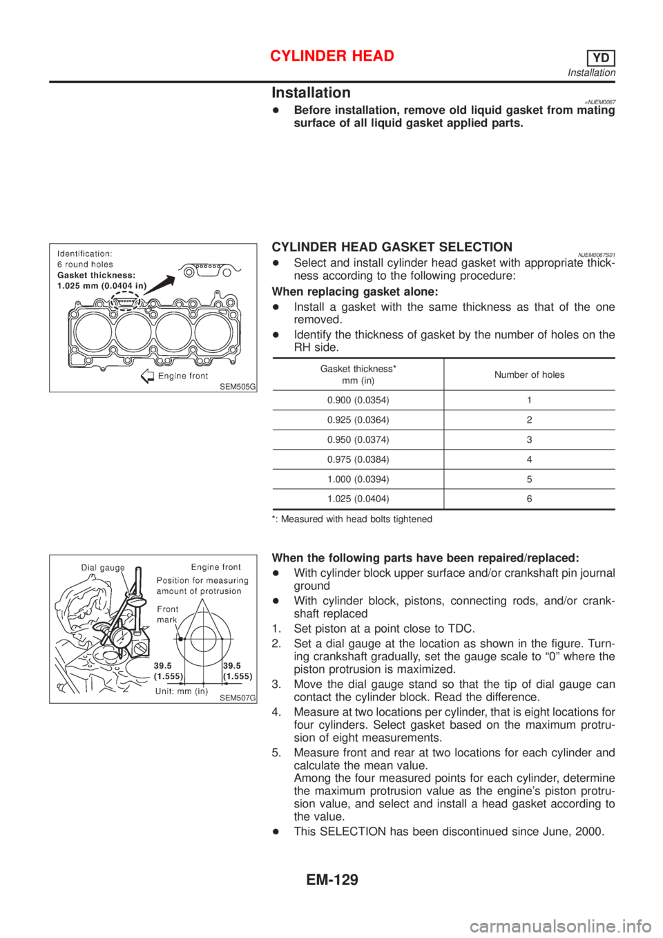
CYLINDER HEAD GASKET SELECTIONNJEM0067S01+Select and install cylinder head gasket with appropriate thick-
ness according to the following procedure:
When replacing gasket alone:
+Install a gasket with the same thickness as that of the one
removed.
+Identify the thickness of gasket by the number of holes on the
RH side.
Gasket thickness*
mm (in)Number of holes
0.900 (0.0354) 1
0.925 (0.0364) 2
0.950 (0.0374) 3
0.975 (0.0384) 4
1.000 (0.0394) 5
1.025 (0.0404) 6
*: Measured with head bolts tightened
SEM507G
When the following parts have been repaired/replaced:
+With cylinder block upper surface and/or crankshaft pin journal
ground
+With cylinder block, pistons, connecting rods, and/or crank-
shaft replaced
1. Set piston at a point close to TDC.
2. Set a dial gauge at the location as shown in the figure. Turn-
ing crankshaft gradually, set the gauge scale to ª0º where the
piston protrusion is maximized.
3. Move the dial gauge stand so that the tip of dial gauge can
contact the cylinder block. Read the difference.
4. Measure at two locations per cylinder, that is eight locations for
four cylinders. Select gasket based on the maximum protru-
sion of eight measurements.
5. Measure front and rear at two locations for each cylinder and
calculate the mean value.
Among the four measured points for each cylinder, determine
the maximum protrusion value as the engine's piston protru-
sion value, and select and install a head gasket according to
the value.
+This SELECTION has been discontinued since June, 2000.
CYLINDER HEADYD
Installation
EM-129
Page 211 of 2493
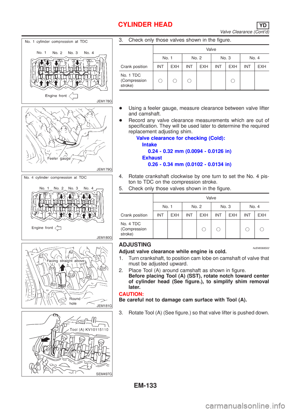
JEM178G
3. Check only those valves shown in the figure.
Crank positionValve
No. 1 No. 2 No. 3 No. 4
INT EXH INT EXH INT EXH INT EXH
No. 1 TDC
(Compression
stroke)jjj j
JEM179G
+Using a feeler gauge, measure clearance between valve lifter
and camshaft.
+Record any valve clearance measurements which are out of
specification. They will be used later to determine the required
replacement adjusting shim.
Valve clearance for checking (Cold):
Intake
0.24 - 0.32 mm (0.0094 - 0.0126 in)
Exhaust
0.26 - 0.34 mm (0.0102 - 0.0134 in)
JEM180G
4. Rotate crankshaft clockwise by one turn to set the No. 4 pis-
ton to TDC on the compression stroke.
5. Check only those valves shown in the figure.
Crank positionValve
No. 1 No. 2 No. 3 No. 4
INT EXH INT EXH INT EXH INT EXH
No. 4 TDC
(Compression
stroke)jj jj
JEM181G
ADJUSTINGNJEM0068S02Adjust valve clearance while engine is cold.
1. Turn crankshaft, to position cam lobe on camshaft of valve that
must be adjusted upward.
2. Place Tool (A) around camshaft as shown in figure.
Before placing Tool (A) (SST), rotate notch toward center
of cylinder head (See figure.), to simplify shim removal
later.
CAUTION:
Be careful not to damage cam surface with Tool (A).
SEM497G
3. Rotate Tool (A) (See figure.) so that valve lifter is pushed down.
CYLINDER HEADYD
Valve Clearance (Cont'd)
EM-133