2001 INFINITI QX4 fuse
[x] Cancel search: fusePage 1318 of 2395

KEY SWITCH (INSERT) CHECK=NBEL0055S04
1 CHECK KEY SWITCH INPUT SIGNAL
Check voltage between smart entrance control unit terminal 32 and ground.
SEL307X
OK or NG
OK©Key switch is OK.
NG©GO TO 2.
2 CHECK KEY SWITCH (INSERT)
Check continuity between terminals 1 and 2.
SEL308X
OK or NG
OK©Check the following.
I7.5A fuse [No. 24, located in fuse block (J/B)]
IHarness for open or short between key switch and fuse
IHarness for open or short between smart entrance control unit and key switch
NG©Replace key switch.
GI
MA
EM
LC
EC
FE
AT
TF
PD
AX
SU
BR
ST
RS
BT
HA
SC
IDX
WARNING CHIME
Trouble Diagnoses (Cont'd)
EL-133
Page 1321 of 2395

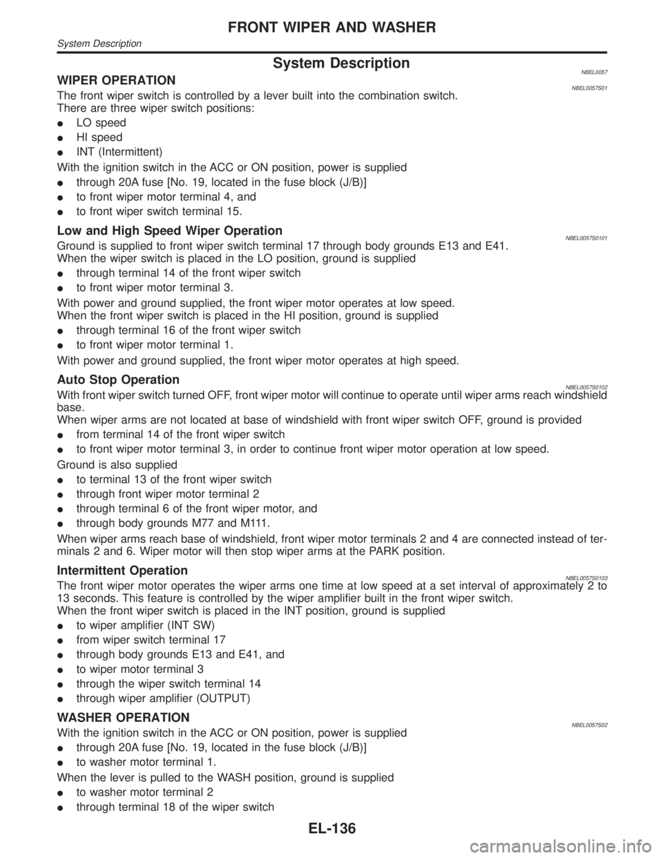
System DescriptionNBEL0057WIPER OPERATIONNBEL0057S01The front wiper switch is controlled by a lever built into the combination switch.
There are three wiper switch positions:
ILO speed
IHI speed
IINT (Intermittent)
With the ignition switch in the ACC or ON position, power is supplied
Ithrough 20A fuse [No. 19, located in the fuse block (J/B)]
Ito front wiper motor terminal 4, and
Ito front wiper switch terminal 15.
Low and High Speed Wiper OperationNBEL0057S0101Ground is supplied to front wiper switch terminal 17 through body grounds E13 and E41.
When the wiper switch is placed in the LO position, ground is supplied
Ithrough terminal 14 of the front wiper switch
Ito front wiper motor terminal 3.
With power and ground supplied, the front wiper motor operates at low speed.
When the front wiper switch is placed in the HI position, ground is supplied
Ithrough terminal 16 of the front wiper switch
Ito front wiper motor terminal 1.
With power and ground supplied, the front wiper motor operates at high speed.
Auto Stop OperationNBEL0057S0102With front wiper switch turned OFF, front wiper motor will continue to operate until wiper arms reach windshield
base.
When wiper arms are not located at base of windshield with front wiper switch OFF, ground is provided
Ifrom terminal 14 of the front wiper switch
Ito front wiper motor terminal 3, in order to continue front wiper motor operation at low speed.
Ground is also supplied
Ito terminal 13 of the front wiper switch
Ithrough front wiper motor terminal 2
Ithrough terminal 6 of the front wiper motor, and
Ithrough body grounds M77 and M111.
When wiper arms reach base of windshield, front wiper motor terminals 2 and 4 are connected instead of ter-
minals 2 and 6. Wiper motor will then stop wiper arms at the PARK position.
Intermittent OperationNBEL0057S0103The front wiper motor operates the wiper arms one time at low speed at a set interval of approximately 2 to
13 seconds. This feature is controlled by the wiper amplifier built in the front wiper switch.
When the front wiper switch is placed in the INT position, ground is supplied
Ito wiper amplifier (INT SW)
Ifrom wiper switch terminal 17
Ithrough body grounds E13 and E41, and
Ito wiper motor terminal 3
Ithrough the wiper switch terminal 14
Ithrough wiper amplifier (OUTPUT)
WASHER OPERATIONNBEL0057S02With the ignition switch in the ACC or ON position, power is supplied
Ithrough 20A fuse [No. 19, located in the fuse block (J/B)]
Ito washer motor terminal 1.
When the lever is pulled to the WASH position, ground is supplied
Ito washer motor terminal 2
Ithrough terminal 18 of the wiper switch
FRONT WIPER AND WASHER
System Description
EL-136
Page 1326 of 2395

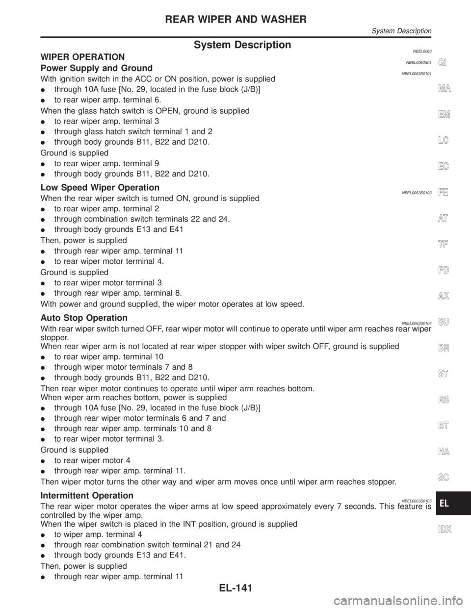
System DescriptionNBEL0063WIPER OPERATIONNBEL0063S01Power Supply and GroundNBEL0063S0101With ignition switch in the ACC or ON position, power is supplied
Ithrough 10A fuse [No. 29, located in the fuse block (J/B)]
Ito rear wiper amp. terminal 6.
When the glass hatch switch is OPEN, ground is supplied
Ito rear wiper amp. terminal 3
Ithrough glass hatch switch terminal 1 and 2
Ithrough body grounds B11, B22 and D210.
Ground is supplied
Ito rear wiper amp. terminal 9
Ithrough body grounds B11, B22 and D210.
Low Speed Wiper OperationNBEL0063S0103When the rear wiper switch is turned ON, ground is supplied
Ito rear wiper amp. terminal 2
Ithrough combination switch terminals 22 and 24.
Ithrough body grounds E13 and E41
Then, power is supplied
Ithrough rear wiper amp. terminal 11
Ito rear wiper motor terminal 4.
Ground is supplied
Ito rear wiper motor terminal 3
Ithrough rear wiper amp. terminal 8.
With power and ground supplied, the wiper motor operates at low speed.
Auto Stop OperationNBEL0063S0104With rear wiper switch turned OFF, rear wiper motor will continue to operate until wiper arm reaches rear wiper
stopper.
When rear wiper arm is not located at rear wiper stopper with wiper switch OFF, ground is supplied
Ito rear wiper amp. terminal 10
Ithrough wiper motor terminals 7 and 8
Ithrough body grounds B11, B22 and D210.
Then rear wiper motor continues to operate until wiper arm reaches bottom.
When wiper arm reaches bottom, power is supplied
Ithrough 10A fuse [No. 29, located in the fuse block (J/B)]
Ithrough rear wiper motor terminals 6 and 7 and
Ithrough rear wiper amp. terminals 10 and 8
Ito rear wiper motor terminal 3.
Ground is supplied
Ito rear wiper motor 4
Ithrough rear wiper amp. terminal 11.
Then wiper motor turns the other way and wiper arm moves once until wiper arm reaches stopper.
Intermittent OperationNBEL0063S0105The rear wiper motor operates the wiper arms at low speed approximately every 7 seconds. This feature is
controlled by the wiper amp.
When the wiper switch is placed in the INT position, ground is supplied
Ito wiper amp. terminal 4
Ithrough rear combination switch terminal 21 and 24
Ithrough body grounds E13 and E41.
Then, power is supplied
Ithrough rear wiper amp. terminal 11
GI
MA
EM
LC
EC
FE
AT
TF
PD
AX
SU
BR
ST
RS
BT
HA
SC
IDX
REAR WIPER AND WASHER
System Description
EL-141
Page 1336 of 2395

Component Parts and Harness Connector
Location
NBEL0072
SEL465X
System DescriptionNBEL0073The rear window defogger system is controlled by the smart entrance control unit. The rear window defogger
operates only for approximately 15 minutes.
Power is supplied at all times
Ito rear window defogger relay terminal 3
Ithrough 20A fuse (No. 56, located in the fuse and fusible link box) and
Ito rear window defogger relay terminal 6
Ithrough 20A fuse (No. 57, located in the fuse and fusible link box)
Ito smart entrance control unit terminal 10
Ithrough 7.5A [No. 24, located in fuse block (J/B)]
With the ignition switch in the ON or START position, power is supplied
Ithrough 7.5A fuse [No. 11, located in the fuse block (J/B)]
Ito the rear window defogger relay terminal 1, and
Ito smart entrance control unit terminal 33.
Ground is supplied
Ito terminal 1 of the rear window defogger switch
Ithrough body grounds M4, M66 and M147(with navigation system),
Ito terminal 32 of the A/C auto amp.
Ithrough body grounds M4, M66 and M147 (without navigation system), or
Ito smart entrance control unit terminal 16
Ithrough body grounds M77 and M111.
GI
MA
EM
LC
EC
FE
AT
TF
PD
AX
SU
BR
ST
RS
BT
HA
SC
IDX
REAR WINDOW DEFOGGER
Component Parts and Harness Connector Location
EL-151
Page 1340 of 2395

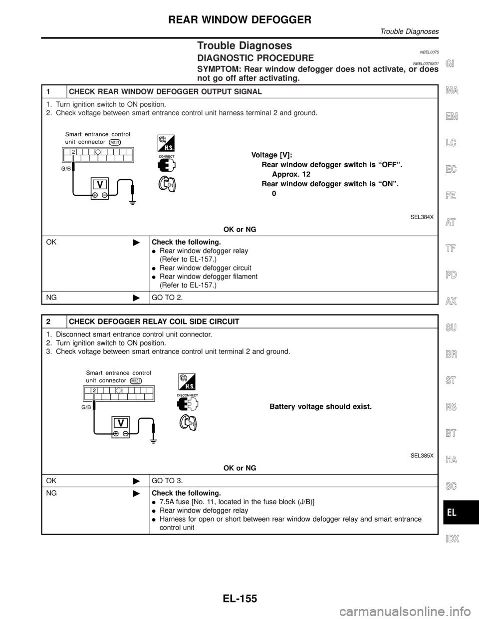
Trouble DiagnosesNBEL0075DIAGNOSTIC PROCEDURENBEL0075S01SYMPTOM: Rear window defogger does not activate, or does
not go off after activating.
1 CHECK REAR WINDOW DEFOGGER OUTPUT SIGNAL
1. Turn ignition switch to ON position.
2. Check voltage between smart entrance control unit harness terminal 2 and ground.
SEL384X
OK or NG
OK©Check the following.
IRear window defogger relay
(Refer to EL-157.)
IRear window defogger circuit
IRear window defogger filament
(Refer to EL-157.)
NG©GO TO 2.
2 CHECK DEFOGGER RELAY COIL SIDE CIRCUIT
1. Disconnect smart entrance control unit connector.
2. Turn ignition switch to ON position.
3. Check voltage between smart entrance control unit terminal 2 and ground.
SEL385X
OK or NG
OK©GO TO 3.
NG©Check the following.
I7.5A fuse [No. 11, located in the fuse block (J/B)]
IRear window defogger relay
IHarness for open or short between rear window defogger relay and smart entrance
control unit
GI
MA
EM
LC
EC
FE
AT
TF
PD
AX
SU
BR
ST
RS
BT
HA
SC
IDX
REAR WINDOW DEFOGGER
Trouble Diagnoses
EL-155
Page 1341 of 2395

3 CHECK REAR WINDOW DEFOGGER SWITCH INPUT SIGNAL
Check continuity between smart entrance control unit terminal 39 and ground.
SEL386X
OK or NG
OK©GO TO 4.
NG©Check the following.
IRear window defogger switch (with navigation system)
(Refer to EL-157.)
IA/C auto amp. (without navigation system)
IHarness for open or short between smart entrance control unit and rear window defog-
ger switch (with navigation system) or A/C auto amp. (without navigation system)
IRear window defogger switch (with navigation system) or A/C auto amp. (without navi-
gation system) ground circuit
4 CHECK IGNITION INPUT SIGNAL
Check voltage between smart entrance control unit terminal 33 and ground.
SEL387X
OK or NG
OK©GO TO 5.
NG©Check the following.
I7.5A fuse [No. 11, located in the fuse block (J/B)]
IHarness for open or short between smart entrance control unit and fuse
REAR WINDOW DEFOGGER
Trouble Diagnoses (Cont'd)
EL-156
Page 1345 of 2395
![INFINITI QX4 2001 Factory Service Manual System DescriptionNBEL0079Refer to Owners Manual for audio system operating instructions.
Power is supplied at all times
Ithrough 15A fuse [No. 4, located in the fuse block (J/B)]
Ito audio unit term INFINITI QX4 2001 Factory Service Manual System DescriptionNBEL0079Refer to Owners Manual for audio system operating instructions.
Power is supplied at all times
Ithrough 15A fuse [No. 4, located in the fuse block (J/B)]
Ito audio unit term](/manual-img/42/57027/w960_57027-1344.png)
System DescriptionNBEL0079Refer to Owner's Manual for audio system operating instructions.
Power is supplied at all times
Ithrough 15A fuse [No. 4, located in the fuse block (J/B)]
Ito audio unit terminal 6,
Ito audio amp. relay terminal 3 and
Ito rear speaker amp. terminal 11.
With the ignition switch in the ACC or ON position, power is supplied
Ithrough 10A fuse [No. 10, located in the fuse block (J/B)]
Ito audio unit terminal 10.
Ground is supplied through the case of the audio unit.
Ground is supplied
Ito audio amp. relay terminal 2
Ithrough body grounds M4, M66 and M147
Ito front door speaker LH terminal 5 and
Ito front door speaker RH terminal 5
Ithrough body grounds M77 and M111
Ito rear speaker amp. terminal 24
Ithrough body grounds B11, B22 and D210.
When the audio unit POWER button is pressed, power is supplied
Ito rear speaker amp. terminal 9 and
Ito audio amp. relay terminal 1
Ifrom audio unit terminal 12.
Then audio amp. relay is energized and power is supplied
Ito front door speaker LH terminal 4 and
Ito front door speaker RH terminal 4.
Audio signals are supplied
Ithrough audio unit terminals 1, 2, 3, 4, 13, 14, 15 and 16
Ito terminals 2 and 6 of the LH and RH front speakers and terminals 5, 7, 18 and 20 of the rear speaker
amp.
Ito LH and RH tweeters through terminals 1 and 3 of the front speakers
Ito rear LH and RH speakers through terminals 1, 2, 25 and 26 of the rear speaker amp.
AUDIO
System Description
EL-160
Page 1351 of 2395

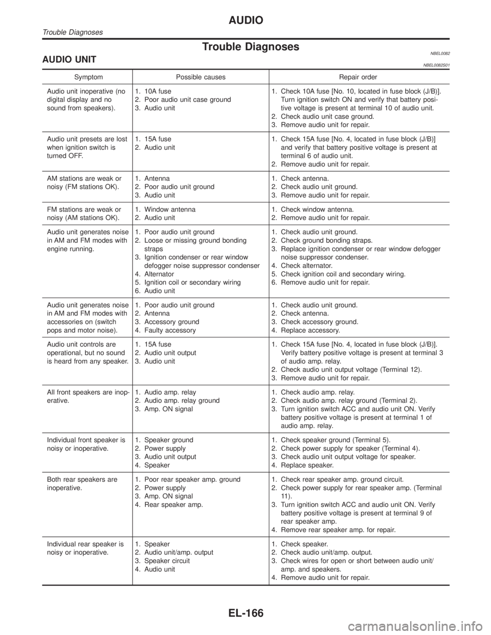
Trouble DiagnosesNBEL0082AUDIO UNITNBEL0082S01
Symptom Possible causes Repair order
Audio unit inoperative (no
digital display and no
sound from speakers).1. 10A fuse
2. Poor audio unit case ground
3. Audio unit1. Check 10A fuse [No. 10, located in fuse block (J/B)].
Turn ignition switch ON and verify that battery posi-
tive voltage is present at terminal 10 of audio unit.
2. Check audio unit case ground.
3. Remove audio unit for repair.
Audio unit presets are lost
when ignition switch is
turned OFF.1. 15A fuse
2. Audio unit1. Check 15A fuse [No. 4, located in fuse block (J/B)]
and verify that battery positive voltage is present at
terminal 6 of audio unit.
2. Remove audio unit for repair.
AM stations are weak or
noisy (FM stations OK).1. Antenna
2. Poor audio unit ground
3. Audio unit1. Check antenna.
2. Check audio unit ground.
3. Remove audio unit for repair.
FM stations are weak or
noisy (AM stations OK).1. Window antenna
2. Audio unit1. Check window antenna.
2. Remove audio unit for repair.
Audio unit generates noise
in AM and FM modes with
engine running.1. Poor audio unit ground
2. Loose or missing ground bonding
straps
3. Ignition condenser or rear window
defogger noise suppressor condenser
4. Alternator
5. Ignition coil or secondary wiring
6. Audio unit1. Check audio unit ground.
2. Check ground bonding straps.
3. Replace ignition condenser or rear window defogger
noise suppressor condenser.
4. Check alternator.
5. Check ignition coil and secondary wiring.
6. Remove audio unit for repair.
Audio unit generates noise
in AM and FM modes with
accessories on (switch
pops and motor noise).1. Poor audio unit ground
2. Antenna
3. Accessory ground
4. Faulty accessory1. Check audio unit ground.
2. Check antenna.
3. Check accessory ground.
4. Replace accessory.
Audio unit controls are
operational, but no sound
is heard from any speaker.1. 15A fuse
2. Audio unit output
3. Audio unit1. Check 15A fuse [No. 4, located in fuse block (J/B)].
Verify battery positive voltage is present at terminal 3
of audio amp. relay.
2. Check audio unit output voltage (Terminal 12).
3. Remove audio unit for repair.
All front speakers are inop-
erative.1. Audio amp. relay
2. Audio amp. relay ground
3. Amp. ON signal1. Check audio amp. relay.
2. Check audio amp. relay ground (Terminal 2).
3. Turn ignition switch ACC and audio unit ON. Verify
battery positive voltage is present at terminal 1 of
audio amp. relay.
Individual front speaker is
noisy or inoperative.1. Speaker ground
2. Power supply
3. Audio unit output
4. Speaker1. Check speaker ground (Terminal 5).
2. Check power supply for speaker (Terminal 4).
3. Check audio unit output voltage for speaker.
4. Replace speaker.
Both rear speakers are
inoperative.1. Poor rear speaker amp. ground
2. Power supply
3. Amp. ON signal
4. Rear speaker amp.1. Check rear speaker amp. ground circuit.
2. Check power supply for rear speaker amp. (Terminal
11).
3. Turn ignition switch ACC and audio unit ON. Verify
battery positive voltage is present at terminal 9 of
rear speaker amp.
4. Remove rear speaker amp. for repair.
Individual rear speaker is
noisy or inoperative.1. Speaker
2. Audio unit/amp. output
3. Speaker circuit
4. Audio unit1. Check speaker.
2. Check audio unit/amp. output.
3. Check wires for open or short between audio unit/
amp. and speakers.
4. Remove audio unit for repair.
AUDIO
Trouble Diagnoses
EL-166