Page 999 of 2395

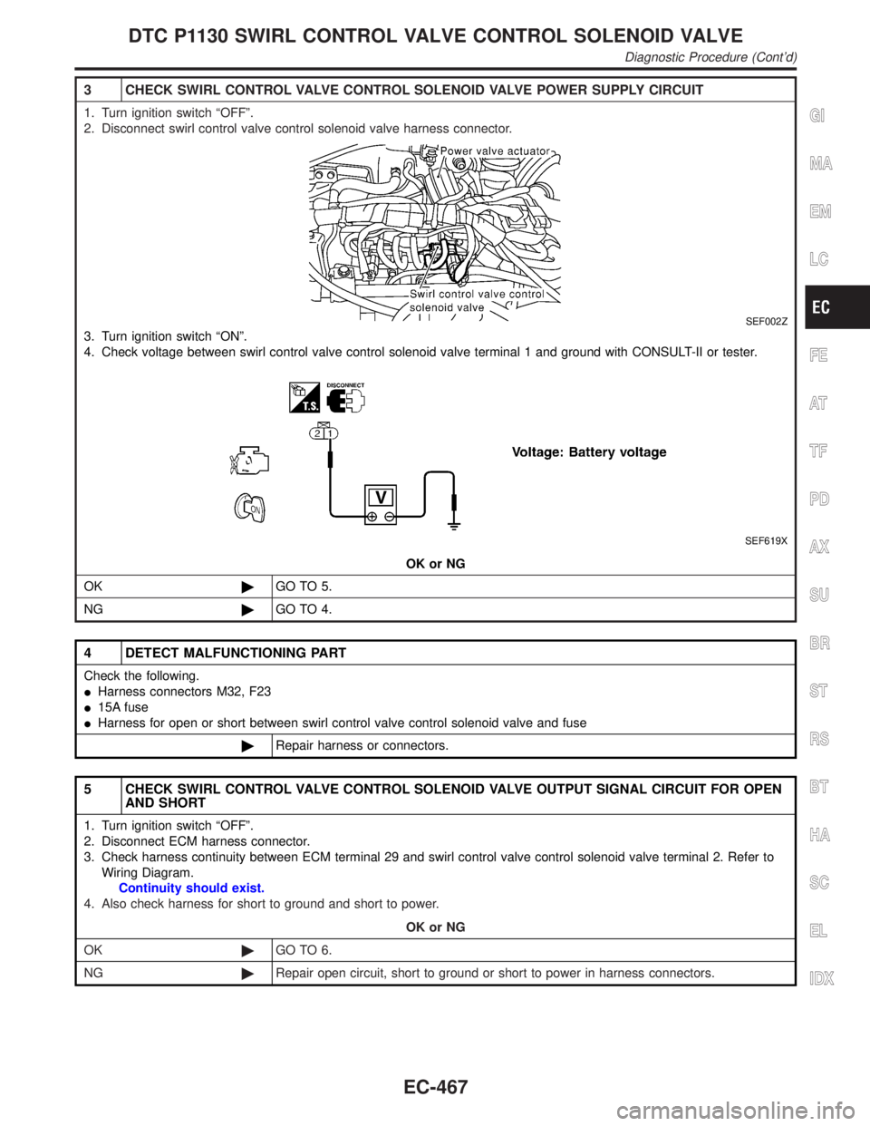
3 CHECK SWIRL CONTROL VALVE CONTROL SOLENOID VALVE POWER SUPPLY CIRCUIT
1. Turn ignition switch ªOFFº.
2. Disconnect swirl control valve control solenoid valve harness connector.
SEF002Z
3. Turn ignition switch ªONº.
4. Check voltage between swirl control valve control solenoid valve terminal 1 and ground with CONSULT-II or tester.
SEF619X
OK or NG
OK©GO TO 5.
NG©GO TO 4.
4 DETECT MALFUNCTIONING PART
Check the following.
IHarness connectors M32, F23
I15A fuse
IHarness for open or short between swirl control valve control solenoid valve and fuse
©Repair harness or connectors.
5 CHECK SWIRL CONTROL VALVE CONTROL SOLENOID VALVE OUTPUT SIGNAL CIRCUIT FOR OPEN
AND SHORT
1. Turn ignition switch ªOFFº.
2. Disconnect ECM harness connector.
3. Check harness continuity between ECM terminal 29 and swirl control valve control solenoid valve terminal 2. Refer to
Wiring Diagram.
Continuity should exist.
4. Also check harness for short to ground and short to power.
OK or NG
OK©GO TO 6.
NG©Repair open circuit, short to ground or short to power in harness connectors.
DTC P1130 SWIRL CONTROL VALVE CONTROL SOLENOID VALVE
Diagnostic Procedure (Cont'd)
EC-464
Page 1002 of 2395

3 CHECK SWIRL CONTROL VALVE CONTROL SOLENOID VALVE POWER SUPPLY CIRCUIT
1. Turn ignition switch ªOFFº.
2. Disconnect swirl control valve control solenoid valve harness connector.
SEF002Z
3. Turn ignition switch ªONº.
4. Check voltage between swirl control valve control solenoid valve terminal 1 and ground with CONSULT-II or tester.
SEF619X
OK or NG
OK©GO TO 5.
NG©GO TO 4.
4 DETECT MALFUNCTIONING PART
Check the following.
IHarness connectors M32, F23
I15A fuse
IHarness for open or short between swirl control valve control solenoid valve and fuse
©Repair harness or connectors.
5 CHECK SWIRL CONTROL VALVE CONTROL SOLENOID VALVE OUTPUT SIGNAL CIRCUIT FOR OPEN
AND SHORT
1. Turn ignition switch ªOFFº.
2. Disconnect ECM harness connector.
3. Check harness continuity between ECM terminal 29 and swirl control valve control solenoid valve terminal 2. Refer to
Wiring Diagram.
Continuity should exist.
4. Also check harness for short to ground and short to power.
OK or NG
OK©GO TO 6.
NG©Repair open circuit, short to ground or short to power in harness connectors.
GI
MA
EM
LC
FE
AT
TF
PD
AX
SU
BR
ST
RS
BT
HA
SC
EL
IDX
DTC P1130 SWIRL CONTROL VALVE CONTROL SOLENOID VALVE
Diagnostic Procedure (Cont'd)
EC-467
Page 1011 of 2395
4 DETECT MALFUNCTIONING PART
Check the following.
IHarness connectors M32, F23
I15A fuse
IHarness for open or short between swirl control valve control solenoid valve and fuse
©Repair harness or connectors.
5 CHECK SWIRL CONTROL VALVE CONTROL SOLENOID VALVE OUTPUT SIGNAL CIRCUIT FOR OPEN
AND SHORT
1. Turn ignition switch ªOFFº.
2. Disconnect ECM harness connector.
3. Check harness continuity between ECM terminal 29 and terminal 2. Refer to Wiring Diagram.
Continuity should exist.
4. Also, check harness for short to ground and short to power.
OK or NG
OK©GO TO 6.
NG©Repair open circuit, short to ground or short to power in harness connectors.
6 CHECK HOSES
Check hoses and tubes between air cleaner and swirl control valve vacuum check switch for clogging or improper connec-
tion.
SEF109L
OK or NG
OK©GO TO 7.
NG©Repair hoses or tubes.
DTC P1130 SWIRL CONTROL VALVE CONTROL SOLENOID VALVE
Diagnostic Procedure (Cont'd)
EC-476
Page 1041 of 2395
6 DETECT MALFUNCTIONING PART
Check the following.
IHarness connectors E1, M1 and M33, F22
IHarness for open or short between ECM relay and condenser
©Repair open circuit or short to ground or short to power in harness or connectors.
7 CHECK IGNITION COIL POWER SUPPLY CIRCUIT-IV
Check voltage between ECM relay terminal 5 and ground with CONSULT-II or tester.
SEF010Z
OK or NG
OK©GO TO 9.
NG©GO TO 8.
8 DETECT MALFUNCTIONING PART
Check the following.
I10A fuse
IHarness for open and short between ECM relay and fuse
©Repair or replace harness or connectors.
9 CHECK ECM RELAY
1. Apply 12V direct current between ECM relay terminals 1 and 2.
2. Check continuity between ECM relay terminals 3 and 5, 6 and 7.
SEF296X
OK or NG
OK©GO TO 17.
NG©Replace ECM relay.
DTC P1320 IGNITION SIGNAL
Diagnostic Procedure (Cont'd)
EC-506
Page 1080 of 2395

Diagnostic ProcedureNBEC0325
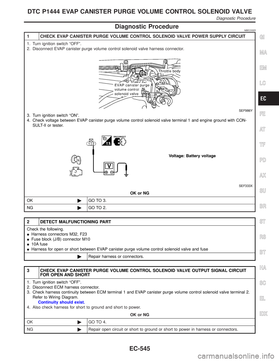
1 CHECK EVAP CANISTER PURGE VOLUME CONTROL SOLENOID VALVE POWER SUPPLY CIRCUIT
1. Turn ignition switch ªOFFº.
2. Disconnect EVAP canister purge volume control solenoid valve harness connector.
SEF986Y
3. Turn ignition switch ªONº.
4. Check voltage between EVAP canister purge volume control solenoid valve terminal 1 and engine ground with CON-
SULT-II or tester.
SEF333X
OK or NG
OK©GO TO 3.
NG©GO TO 2.
2 DETECT MALFUNCTIONING PART
Check the following.
IHarness connectors M32, F23
IFuse block (J/B) connector M10
I10A fuse
IHarness for open or short between EVAP canister purge volume control solenoid valve and fuse
©Repair harness or connectors.
3 CHECK EVAP CANISTER PURGE VOLUME CONTROL SOLENOID VALVE OUTPUT SIGNAL CIRCUIT
FOR OPEN AND SHORT
1. Turn ignition switch ªOFFº.
2. Disconnect ECM harness connector.
3. Check harness continuity between ECM terminal 1 and EVAP canister purge volume control solenoid valve terminal 2.
Refer to Wiring Diagram.
Continuity should exist.
4. Also check harness for short to ground and short to power.
OK or NG
OK©GO TO 4.
NG©Repair open circuit or short to ground or short to power in harness or connectors.
GI
MA
EM
LC
FE
AT
TF
PD
AX
SU
BR
ST
RS
BT
HA
SC
EL
IDX
DTC P1444 EVAP CANISTER PURGE VOLUME CONTROL SOLENOID VALVE
Diagnostic Procedure
EC-545
Page 1124 of 2395

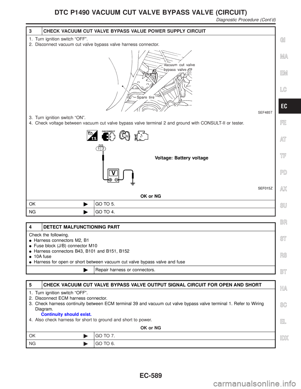
3 CHECK VACUUM CUT VALVE BYPASS VALUE POWER SUPPLY CIRCUIT
1. Turn ignition switch ªOFFº.
2. Disconnect vacuum cut valve bypass valve harness connector.
SEF485T
3. Turn ignition switch ªONº.
4. Check voltage between vacuum cut valve bypass valve terminal 2 and ground with CONSULT-II or tester.
SEF015Z
OK or NG
OK©GO TO 5.
NG©GO TO 4.
4 DETECT MALFUNCTIONING PART
Check the following.
IHarness connectors M2, B1
IFuse block (J/B) connector M10
IHarness connectors B43, B101 and B151, B152
I10A fuse
IHarness for open or short between vacuum cut valve bypass valve and fuse
©Repair harness or connectors.
5 CHECK VACUUM CUT VALVE BYPASS VALVE OUTPUT SIGNAL CIRCUIT FOR OPEN AND SHORT
1. Turn ignition switch ªOFFº.
2. Disconnect ECM harness connector.
3. Check harness continuity between ECM terminal 39 and vacuum cut valve bypass valve terminal 1. Refer to Wiring
Diagram.
Continuity should exist.
4. Also check harness for short to ground and short to power.
OK or NG
OK©GO TO 7.
NG©GO TO 6.
GI
MA
EM
LC
FE
AT
TF
PD
AX
SU
BR
ST
RS
BT
HA
SC
EL
IDX
DTC P1490 VACUUM CUT VALVE BYPASS VALVE (CIRCUIT)
Diagnostic Procedure (Cont'd)
EC-589
Page 1149 of 2395

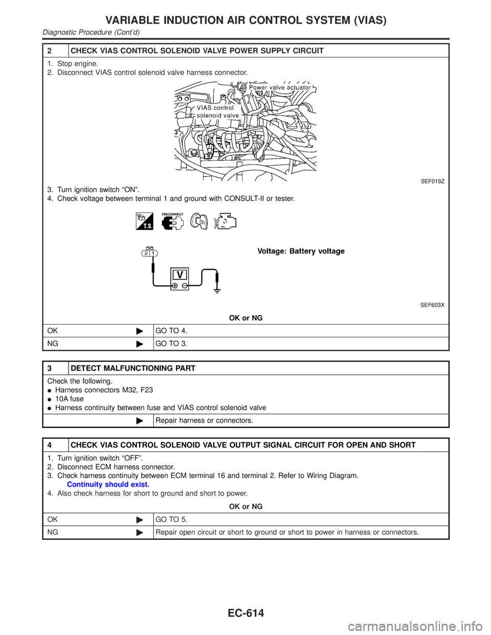
2 CHECK VIAS CONTROL SOLENOID VALVE POWER SUPPLY CIRCUIT
1. Stop engine.
2. Disconnect VIAS control solenoid valve harness connector.
SEF019Z
3. Turn ignition switch ªONº.
4. Check voltage between terminal 1 and ground with CONSULT-II or tester.
SEF603X
OK or NG
OK©GO TO 4.
NG©GO TO 3.
3 DETECT MALFUNCTIONING PART
Check the following.
IHarness connectors M32, F23
I10A fuse
IHarness continuity between fuse and VIAS control solenoid valve
©Repair harness or connectors.
4 CHECK VIAS CONTROL SOLENOID VALVE OUTPUT SIGNAL CIRCUIT FOR OPEN AND SHORT
1. Turn ignition switch ªOFFº.
2. Disconnect ECM harness connector.
3. Check harness continuity between ECM terminal 16 and terminal 2. Refer to Wiring Diagram.
Continuity should exist.
4. Also check harness for short to ground and short to power.
OK or NG
OK©GO TO 5.
NG©Repair open circuit or short to ground or short to power in harness or connectors.
VARIABLE INDUCTION AIR CONTROL SYSTEM (VIAS)
Diagnostic Procedure (Cont'd)
EC-614
Page 1154 of 2395
3 CHECK INJECTOR POWER SUPPLY CIRCUIT
1. Turn ignition switch ªOFFº.
SEF023Z
2. Turn ignition switch ªONº.
3. Check voltage between injector terminal 1 and ground with CONSULT-II or tester.
SEF364Z
OK or NG
OK©GO TO 5.
NG©GO TO 4.
4 DETECT MALFUNCTIONING PART
Check the following.
IHarness connectors M33, F22
IHarness connectors F5, F100
IFuse block (J/B) connector M10
I10A fuse
IHarness for open or short between injector and fuse
©Repair harness or connectors.
5 CHECK INJECTOR OUTPUT SIGNAL CIRCUIT FOR OPEN AND SHORT
1. Turn ignition switch ªOFFº.
2. Disconnect ECM harness connector.
3. Check harness continuity between injector terminal 2 and ECM terminals 103, 104, 107, 101, 105, 102. Refer to Wiring
Diagram.
Continuity should exist.
4. Also check harness for short to ground and short to power.
OK or NG
OK©GO TO 7.
NG©GO TO 6.
GI
MA
EM
LC
FE
AT
TF
PD
AX
SU
BR
ST
RS
BT
HA
SC
EL
IDX
INJECTOR
Diagnostic Procedure (Cont'd)
EC-619