2001 INFINITI QX4 fuse
[x] Cancel search: fusePage 1264 of 2395

Trouble DiagnosesNBEL0033
Symptom Possible cause Repair order
Turn signal and hazard warning
lamps do not operate.1. Hazard switch
2. Combination flasher unit
3. Open in combination flasher
unit circuit1. Check hazard switch.
2. Refer to combination flasher unit check.
3. Check wiring to combination flasher unit for open
circuit.
Turn signal lamps do not operate
but hazard warning lamps operate.1. 7.5A fuse
2. Hazard switch
3. Combination switch (turn signal)
4. Open in combination switch
(turn signal) circuit1. Check 7.5A fuse [No. 12, located in fuse block
(J/B)]. Turn ignition switch ON and verify battery
positive voltage is present at terminal 2 of hazard
switch.
2. Check hazard switch.
3. Check combination switch (turn signal).
4. Check the wire between combination flasher unit
terminal 3 and combination switch (turn signal) ter-
minal 1 for open circuit.
Hazard warning lamps do not oper-
ate but fog lamps (turn signal)
operate.1. 15A fuse
2. Hazard switch
3. Open in hazard switch circuit1. Check 15A fuse [No. 20, located in fuse block (J/B)].
Verify battery positive voltage is present at terminal
3 of hazard switch.
2. Check hazard switch.
3. Check the wire between combination flasher unit
terminal 3 and hazard switch terminal 4 for open cir-
cuit.
Front fog lamp (turn signal) LH or
RH does not operate.1. Bulb
2. Grounds E13 and E41
3. Open in front fog lamp (turn sig-
nal) circuit1. Check bulb.
2. Check grounds E13 and E41.
3. Check harness between front fog lamp (turn signal)
and combination switch.
Rear combination lamp LH does
not operate.1. Bulb
2. Grounds B11, B22 and D210
3. Open in rear combination lamp
LH circuit1. Check bulb.
2. Check grounds B11, B22 and D210.
3. Check harness between rear combination lamp LH
and hazard switch.
Rear combination lamp RH does
not operate.1. Bulb
2. Grounds B55 and B75
3. Open in rear combination lamp
RH circuit1. Check bulb.
2. Check grounds B55 and B75.
3. Check harness between rear combination lamp RH
and hazard switch.
LH and RH turn indicators do not
operate.1. Ground 1. Check grounds M4, M66 and M147.
LH or RH turn indicator does not
operate.1. Bulb
2. Open in turn indicator circuit1. Check bulb in combination meter.
2. Check harness between combination meter and haz-
ard switch.
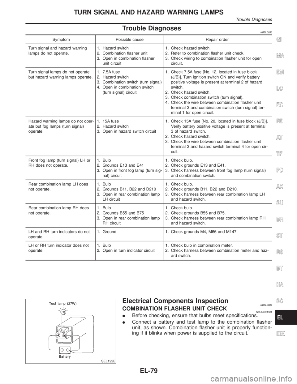
SEL122E
Electrical Components InspectionNBEL0034COMBINATION FLASHER UNIT CHECKNBEL0034S01IBefore checking, ensure that bulbs meet specifications.
IConnect a battery and test lamp to the combination flasher
unit, as shown. Combination flasher unit is properly function-
ing if it blinks when power is supplied to the circuit.
GI
MA
EM
LC
EC
FE
AT
TF
PD
AX
SU
BR
ST
RS
BT
HA
SC
IDX
TURN SIGNAL AND HAZARD WARNING LAMPS
Trouble Diagnoses
EL-79
Page 1265 of 2395

System DescriptionNBEL0035The illumination lamp operation is controlled by the lighting switch which is built into the combination switch
and headlamp battery saver control unit. The battery saver system is controlled by the headlamp battery saver
control unit and smart entrance control unit.
Power is supplied at all times
Ito tail lamp relay terminals 2 and 3
Ithrough 10A fuse (No. 61, located in the fuse and fusible link box), and
Ito headlamp battery saver control unit terminal 7, and
Ito smart entrance control unit terminal 10
Ithrough 7.5A fuse [No. 24, located in the fuse block (J/B)].
When ignition switch is in ON or START position, power is supplied
Ito headlamp battery saver control unit terminal 1
Ithrough 10A fuse [No. 16, located in the fuse block (J/B)], and
Ito headlamp battery saver control unit terminal 10, and
Ito smart entrance control unit terminal 33
Ithrough 7.5A fuse [No. 11, located in the fuse block (J/B)].
Ground is supplied to headlamp battery saver control unit terminals 4 and 11.
LIGHTING OPERATION BY LIGHTING SWITCHNBEL0035S01When lighting switch is 1ST (or 2ND) position, ground is supplied
Ito tail lamp relay terminal 1 from headlamp battery saver control unit terminals 6 and 14
Ithrough headlamp battery saver control unit terminals 5 and 13, and
Ithrough body grounds E13 and E41.
Tail lamp relay is then energized and illumination lamps illuminate.
The lighting switch must be in the 1ST or 2ND position for illumination.
LIGHTING OPERATION BY AUTO LIGHT CONTROL SYSTEMNBEL0035S03When auto light operation is operated, ground is supplied
Ito tail lamp relay terminal 1 from headlamp battery saver control unit terminals 6 and 14
Ithrough headlamp battery saver control unit terminals 5 and 13, and
Ithrough auto light control unit terminal 7.
Tail lamp relay is then energized and the illumination lamps illuminate.
The illumination control switch that controls the amount of current to the illumination system. As the amount
of current increases, the illumination becomes brighter.
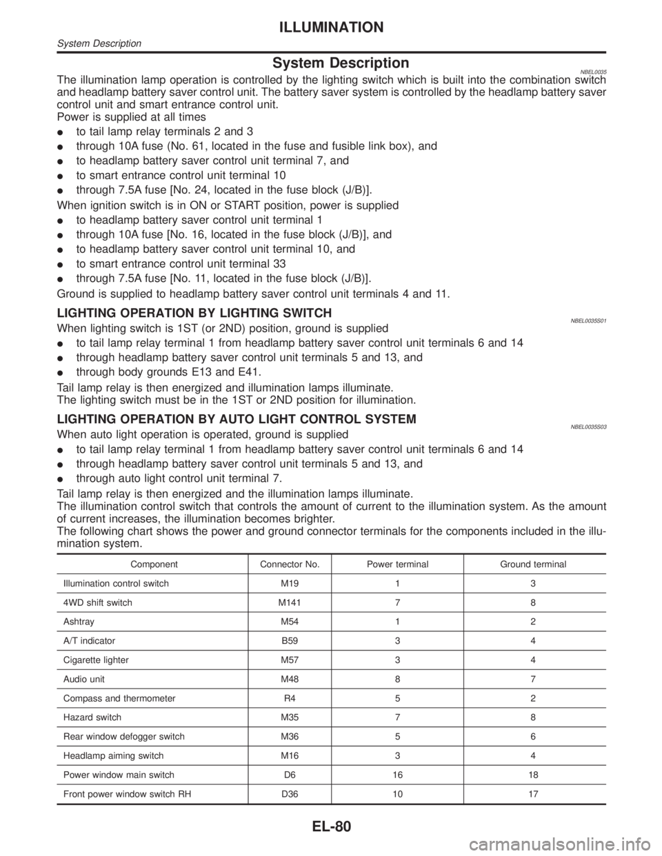
The following chart shows the power and ground connector terminals for the components included in the illu-
mination system.
Component Connector No. Power terminal Ground terminal
Illumination control switch M19 1 3
4WD shift switch M141 7 8
Ashtray M54 1 2
A/T indicator B59 3 4
Cigarette lighter M57 3 4
Audio unit M48 8 7
Compass and thermometer R4 5 2
Hazard switch M35 7 8
Rear window defogger switch M36 5 6
Headlamp aiming switch M16 3 4
Power window main switch D6 16 18
Front power window switch RH D36 10 17
ILLUMINATION
System Description
EL-80
Page 1273 of 2395
![INFINITI QX4 2001 Factory Service Manual System DescriptionNBEL0038POWER SUPPLY AND GROUNDNBEL0038S06Power is supplied at all times:
Ithrough 7.5A fuse [No. 24, located in the fuse block (J/B)]
Ito key switch terminal 2 and
Ito smart entranc INFINITI QX4 2001 Factory Service Manual System DescriptionNBEL0038POWER SUPPLY AND GROUNDNBEL0038S06Power is supplied at all times:
Ithrough 7.5A fuse [No. 24, located in the fuse block (J/B)]
Ito key switch terminal 2 and
Ito smart entranc](/manual-img/42/57027/w960_57027-1272.png)
System DescriptionNBEL0038POWER SUPPLY AND GROUNDNBEL0038S06Power is supplied at all times:
Ithrough 7.5A fuse [No. 24, located in the fuse block (J/B)]
Ito key switch terminal 2 and
Ito smart entrance control unit terminal 10.
When the key is removed from ignition key cylinder, power is interrupted:
Ithrough key switch terminal 1
Ito smart entrance control unit terminal 32.
With the ignition key switch in the ON or START position, power is supplied:
Ithrough 7.5A fuse [No. 11, located in the fuse block (J/B)]
Ito smart entrance control unit terminal 33.
Ground is supplied:
Ito smart entrance control unit terminal 16
Ithrough body grounds terminals M77 and M111.
When the front driver side door is opened, ground is supplied:
Ithrough body grounds B11, B22 and D210
Ito front door switch (LH) terminal 2
Ifrom front door switch (LH) terminal 1
Ito smart entrance control unit terminal 29.
When the front passenger side door is opened, ground is supplied:
Ithrough case ground of front door switch (RH)
Ifrom front door switch (RH) terminal 1
Ito smart entrance control unit terminal 40.
When any other door (except front door) is opened, ground is supplied to smart entrance control unit termi-
nal 28 in the same manner as the front door switch (front passenger side).
When the front driver side door is unlocked, the smart entrance control unit receives a ground signal:
Ithrough body grounds terminals M77 and M111
Ito front door lock actuator (driver side unlock sensor) terminal 2
Ifrom front door lock actuator (driver side unlock sensor) terminal 4
Ito smart entrance control unit terminal 36.
When a signal, or combination of signals is received by the smart entrance control unit, ground is supplied:
Ithrough smart entrance control unit terminal 8
Ito interior lamp terminal 2.
With power and ground supplied, the interior lamp illuminates.
SWITCH OPERATIONNBEL0038S07When interior lamp switch is ON, ground is supplied:
Ithrough case grounds of interior lamp
Ito interior lamp.
And power is supplied:
Ito interior lamp terminal 1
Ifrom smart entrance control unit terminal 17.
When spot lamp (LH and/or RH) is ON, ground is supplied:
Ithrough body grounds M4, M66 and M147
Ito spot lamp terminal 2.
And power is supplied:
Ito spot lamp terminal 1
Ifrom smart entrance control unit terminal 17.
When vanity mirror illumination (LH and/or RH) is ON, ground is supplied:
Ithrough body grounds M4, M66 and M147
Ito vanity mirror illuminations (LH and RH) terminals 2.
INTERIOR, SPOT, VANITY MIRROR AND LUGGAGE ROOM LAMPS
System Description
EL-88
Page 1280 of 2395
![INFINITI QX4 2001 Factory Service Manual POWER SUPPLY AND GROUND CIRCUITNBEL0042S08Power is supplied at all times
Ithrough 7.5A fuse [No. 24, located in the fuse block (J/B)]
Ito combination meter terminal 62.
With the ignition switch in the INFINITI QX4 2001 Factory Service Manual POWER SUPPLY AND GROUND CIRCUITNBEL0042S08Power is supplied at all times
Ithrough 7.5A fuse [No. 24, located in the fuse block (J/B)]
Ito combination meter terminal 62.
With the ignition switch in the](/manual-img/42/57027/w960_57027-1279.png)
POWER SUPPLY AND GROUND CIRCUITNBEL0042S08Power is supplied at all times
Ithrough 7.5A fuse [No. 24, located in the fuse block (J/B)]
Ito combination meter terminal 62.
With the ignition switch in the ON or START position, power is supplied
Ithrough 10A fuse [No. 8, located in the fuse block (J/B)]
Ito combination meter terminal 66.
Ground is supplied
Ito combination meter terminal 59
Ithrough body grounds M4, M66 and M147.
WATER TEMPERATURE GAUGENBEL0042S01The water temperature gauge indicates the engine coolant temperature. The reading on the gauge is based
on the resistance of the thermal transmitter.
As the temperature of the coolant increases, the resistance of the thermal transmitter decreases. A variable
ground is supplied to terminal 18 of the combination meter for the water temperature gauge. The needle on
the gauge moves from ªCº to ªHº.
TACHOMETERNBEL0042S02The tachometer indicates engine speed in revolutions per minute (rpm).
The tachometer is regulated by a signal
Ifrom terminal 25 of the ECM
Ito combination meter terminal 16 for the tachometer.
FUEL GAUGENBEL0042S03The fuel gauge indicates the approximate fuel level in the fuel tank.
The fuel gauge is regulated by a variable ground signal supplied
Ito combination meter terminal 17 for the fuel gauge
Ifrom terminal 3 of the fuel level sensor unit
Ithrough terminal 2 of the fuel level sensor unit and
Ithrough body grounds B11, B22 and D210.
SPEEDOMETERNBEL0042S04The vehicle speed sensor provides a voltage signal to the combination meter for the speedometer.
The voltage is supplied
Ifrom combination meter terminal 15 for the speedometer
Ito terminal 2 of the vehicle speed sensor.
The speedometer converts the voltage into the vehicle speed displayed.
GI
MA
EM
LC
EC
FE
AT
TF
PD
AX
SU
BR
ST
RS
BT
HA
SC
IDX
METERS AND GAUGES
System Description (Cont'd)
EL-95
Page 1288 of 2395

SEL179WB
POWER SUPPLY AND GROUND CIRCUIT CHECK=NBEL0201S03Power Supply Circuit CheckNBEL0201S0301
Terminals Ignition switch position
(+) (þ) OFF ACC ON
62 GroundBattery
voltageBattery
voltageBattery
voltage
66 Ground 0V 0VBattery
voltage
If NG, check the following.
I10A fuse [No. 12, located in fuse block (J/B)]
I10A fuse [No. 30, located in fuse block (J/B)]
IHarness for open or short between fuse and combination
meter
SEL180WA
Ground Circuit CheckNBEL0201S0302
Terminals Continuity
59 - Ground Yes
GI
MA
EM
LC
EC
FE
AT
TF
PD
AX
SU
BR
ST
RS
BT
HA
SC
IDX
METERS AND GAUGES
Trouble Diagnoses (Cont'd)
EL-103
Page 1297 of 2395

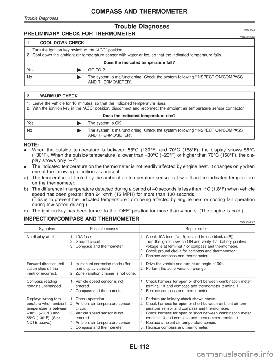
Trouble DiagnosesNBEL0048PRELIMINARY CHECK FOR THERMOMETERNBEL0048S02
1 COOL DOWN CHECK
1. Turn the ignition key switch to the ªACCº position.
2. Cool down the ambient air temperature sensor with water or ice, so that the indicated temperature falls.
Does the indicated temperature fall?
Ye s©GO TO 2.
No©The system is malfunctioning. Check the system following ªINSPECTION/COMPASS
AND THERMOMETERº.
2 WARM UP CHECK
1. Leave the vehicle for 10 minutes, so that the indicated temperature rises.
2. With the ignition key in the ªACCº position, disconnect and reconnect the ambient air temperature sensor connector.
Does the indicated temperature rise?
Ye s©The system is OK.
No©The system is malfunctioning. Check the system following ªINSPECTION/COMPASS
AND THERMOMETERº.
NOTE:
IWhen the outside temperature is between 55ÉC (130ÉF) and 70ÉC (158ÉF), the display shows 55ÉC
(130ÉF). When the outside temperature is lower than þ30ÉC (þ20ÉF) or higher than 70ÉC (158ÉF), the dis-
play shows only ª---º.
IThe indicated temperature on the thermometer is not readily affected by engine heat. It changes only when
one of the following conditions is present.
a) The temperature detected by the ambient air temperature sensor is lower than the indicated temperature
on the thermometer.
b) The difference in temperature detected during a period of 40 seconds is less than 1ÉC (1.8ÉF) when vehicle
speed has been greater than 24 km/h (15 MPH) for more than 100 seconds.
(This is to prevent the indicated temperature from being affected by engine heat or cooling fan operation
during low-speed driving.)
c) The ignition key has been turned to the ªOFFº position for more than 4 hours. (The engine is cold.)
INSPECTION/COMPASS AND THERMOMETERNBEL0048S01
Symptom Possible causes Repair order
No display at all 1. 10A fuse
2. Ground circuit
3. Compass and thermometer1. Check 10A fuse [No. 9, located in fuse block (J/B)].
Turn the ignition switch ON and verify that battery positive
voltage is at terminal 7 of compass and thermometer.
2. Check ground circuit for compass and thermometer.
3. Replace compass and thermometer.
Forward direction indi-
cation slips off the
mark or incorrect.1. In manual correction mode (Bar
and display vanish.)
2. Zone variation change is not done.1. Drive the vehicle and turn at an angle of 90É.
2. Perform the zone variation change.
Compass reading
remains unchanged.1. Vehicle speed sensor is not
entered.
2. Compass and thermometer1. Check harness for open or short between combination meter
terminal 13 and compass and thermometer terminal 1.
2. Replace compass and thermometer.
Displays wrong tem-
perature when ambient
temperature is between
þ30ÉC (þ20ÉF) and
55ÉC (130ÉF). (See
NOTE above.)1. Check operation
2. Ambient air temperature sensor
circuit
3. Vehicle speed sensor is not
entered.
4. Ambient air temperature sensor
5. Compass and thermometer1. Perform preliminary check shown above.
2. Check harness for open or short between ambient air tem-
perature sensor and compass and thermometer.
3. Check harness for open or short between combination meter
terminal 13 and compass and thermometer terminal 1.
4. Replace ambient air temperature sensor.
5. Replace compass and thermometer.
COMPASS AND THERMOMETER
Trouble Diagnoses
EL-112
Page 1310 of 2395

Component Parts and Harness Connector
Location
NBEL0052
SEL046W
System DescriptionNBEL0053The warning chime is controlled by the smart entrance control unit.
The warning chime is located in the smart entrance control unit.
Power is supplied at all times
Ithrough 7.5A fuse [No. 24, located in the fuse block (J/B)]
Ito smart entrance control unit terminal 10, and
Ito key switch terminal 2, and
Ithrough 10A fuse [No. 61, located in the fuse block (J/B)]
Ito tail lamp relay terminals 2 and 3.
With the ignition switch in the ON or START position, power is supplied
Ithrough 7.5A fuse [No. 11, located in the fuse block (J/B)]
Ito smart entrance control unit terminal 33.
Ground is supplied to smart entrance control unit terminal 16 through body grounds M77 and M111.
IGNITION KEY WARNING CHIMENBEL0053S01With the key in the ignition switch in the OFF or ACC position, and the driver's door open, the warning chime
will sound. Power is supplied
Ifrom key switch terminal 1
Ito smart entrance control unit terminal 32.
Ground is supplied
Ifrom front door switch LH terminal 1
Ito smart entrance control unit terminal 29.
Front door switch LH terminal 2 is grounded through body grounds B11, B22 and D210.
LIGHT WARNING CHIMENBEL0053S02With ignition switch OFF or ACC, driver's door open, warning chime will sound. [Except when headlamp bat-
tery saver control operates (for 45 seconds after ignition switch is turned to OFF or ACC position) and head-
lamps do not illuminate.] Power is supplied.
Ifrom tail lamp relay terminal 5
Ito smart entrance control unit terminal 34.
Ground is supplied
Ifrom front door switch LH terminal 1
GI
MA
EM
LC
EC
FE
AT
TF
PD
AX
SU
BR
ST
RS
BT
HA
SC
IDX
WARNING CHIME
Component Parts and Harness Connector Location
EL-125
Page 1316 of 2395

LIGHTING SWITCH INPUT SIGNAL CHECK=NBEL0055S03
1 CHECK LIGHTING SWITCH INPUT SIGNAL
Check voltage between smart entrance control unit terminal 34 and ground.
SEL377X
OK or NG
OK©Lighting switch is OK.
NG©GO TO 2.
2 CHECK FUSE
Is 10A fuse (No. 61, located in the fuse and fusible link box) OK?
OK or NG
OK©GO TO 3.
NG©Replace fuse.
3 CHECK TAIL LAMP RELAY CIRCUIT
Check voltage between headlamp battery saver control unit terminal 6, 14 and ground.
SEL378X
OK or NG
OK©Check the following.
ITail lamp relay
IHarness for open or short between smart entrance control unit and tail lamp relay.
NG©GO TO 4.
GI
MA
EM
LC
EC
FE
AT
TF
PD
AX
SU
BR
ST
RS
BT
HA
SC
IDX
WARNING CHIME
Trouble Diagnoses (Cont'd)
EL-131