Page 1417 of 2395
POWER SUPPLY AND GROUND CIRCUIT CHECK=NBEL0218S03
1 CHECK POWER SUPPLY CIRCUIT FOR ASCD CONTROL UNIT
1. Disconnect ASCD control unit harness connector.
2. Turn ignition switch ON.
3. Check voltage between ASCD control unit harness connector terminal 5 and ground.
SEL256WB
Refer to wiring diagram in EL-227.
Ye s©GO TO 2.
No©Check the following.
I7.5A fuse (No. 11 located in the fuse block)
IHarness for open or short
2 CHECK GROUND CIRCUIT FOR ASCD CONTROL UNIT
Check continuity between ASCD control unit harness connector terminal 17 and body ground.
SEL257WB
Refer to wiring diagram in EL-227.
Ye s©Power supply and ground circuit is OK.
No©Repair harness.
AUTOMATIC SPEED CONTROL DEVICE (ASCD)
Trouble Diagnoses (Cont'd)
EL-232
Page 1418 of 2395

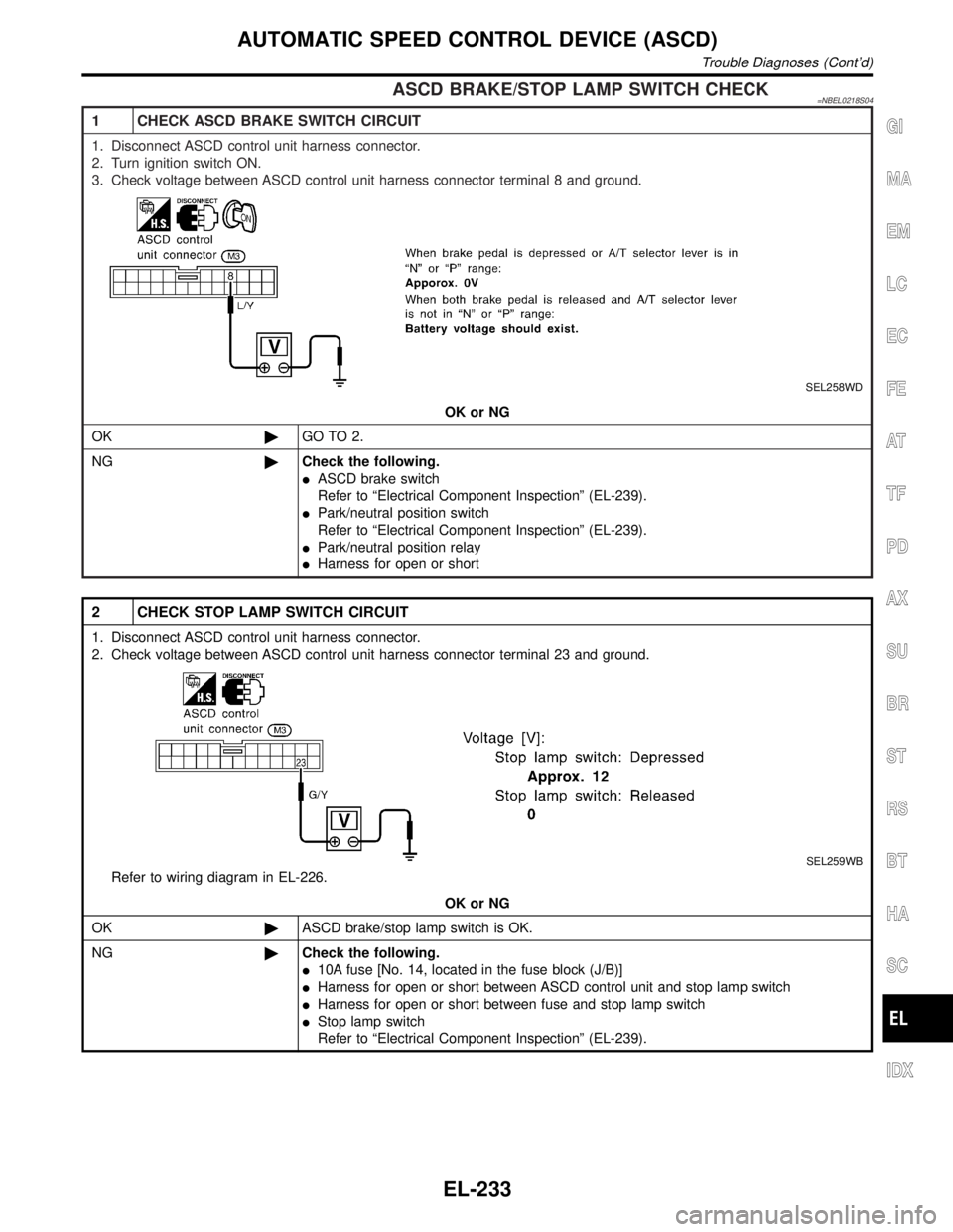
ASCD BRAKE/STOP LAMP SWITCH CHECK=NBEL0218S04
1 CHECK ASCD BRAKE SWITCH CIRCUIT
1. Disconnect ASCD control unit harness connector.
2. Turn ignition switch ON.
3. Check voltage between ASCD control unit harness connector terminal 8 and ground.
SEL258WD
OK or NG
OK©GO TO 2.
NG©Check the following.
IASCD brake switch
Refer to ªElectrical Component Inspectionº (EL-239).
IPark/neutral position switch
Refer to ªElectrical Component Inspectionº (EL-239).
IPark/neutral position relay
IHarness for open or short
2 CHECK STOP LAMP SWITCH CIRCUIT
1. Disconnect ASCD control unit harness connector.
2. Check voltage between ASCD control unit harness connector terminal 23 and ground.
SEL259WB
Refer to wiring diagram in EL-226.
OK or NG
OK©ASCD brake/stop lamp switch is OK.
NG©Check the following.
I10A fuse [No. 14, located in the fuse block (J/B)]
IHarness for open or short between ASCD control unit and stop lamp switch
IHarness for open or short between fuse and stop lamp switch
IStop lamp switch
Refer to ªElectrical Component Inspectionº (EL-239).
GI
MA
EM
LC
EC
FE
AT
TF
PD
AX
SU
BR
ST
RS
BT
HA
SC
IDX
AUTOMATIC SPEED CONTROL DEVICE (ASCD)
Trouble Diagnoses (Cont'd)
EL-233
Page 1419 of 2395
ASCD STEERING SWITCH CHECK=NBEL0218S05
1 CHECK ASCD STEERING SWITCH CIRCUIT FOR ASCD CONTROL UNIT
Check voltage between ASCD control unit harness connector terminals and ground.
SEL260WC
Refer to wiring diagram in EL-226.
OK or NG
OK©ASCD steering switch is OK.
NG©GO TO 2.
2 CHECK POWER SUPPLY FOR ASCD STEERING SWITCH
Does horn work?
Ye s©GO TO 3.
No©Check the following.
I7.5A fuse (No. 52, located in the relay box)
IHorn relay
IHorn circuit
3 CHECK ASCD STEERING SWITCH
1. Disconnect ASCD steering switch.
2. Check continuity between terminals by pushing each switch.
SEL764WA
OK or NG
OK©Check harness for open or short between ASCD steering switch and ASCD control unit.
NG©Replace ASCD steering switch.
AUTOMATIC SPEED CONTROL DEVICE (ASCD)
Trouble Diagnoses (Cont'd)
EL-234
Page 1426 of 2395

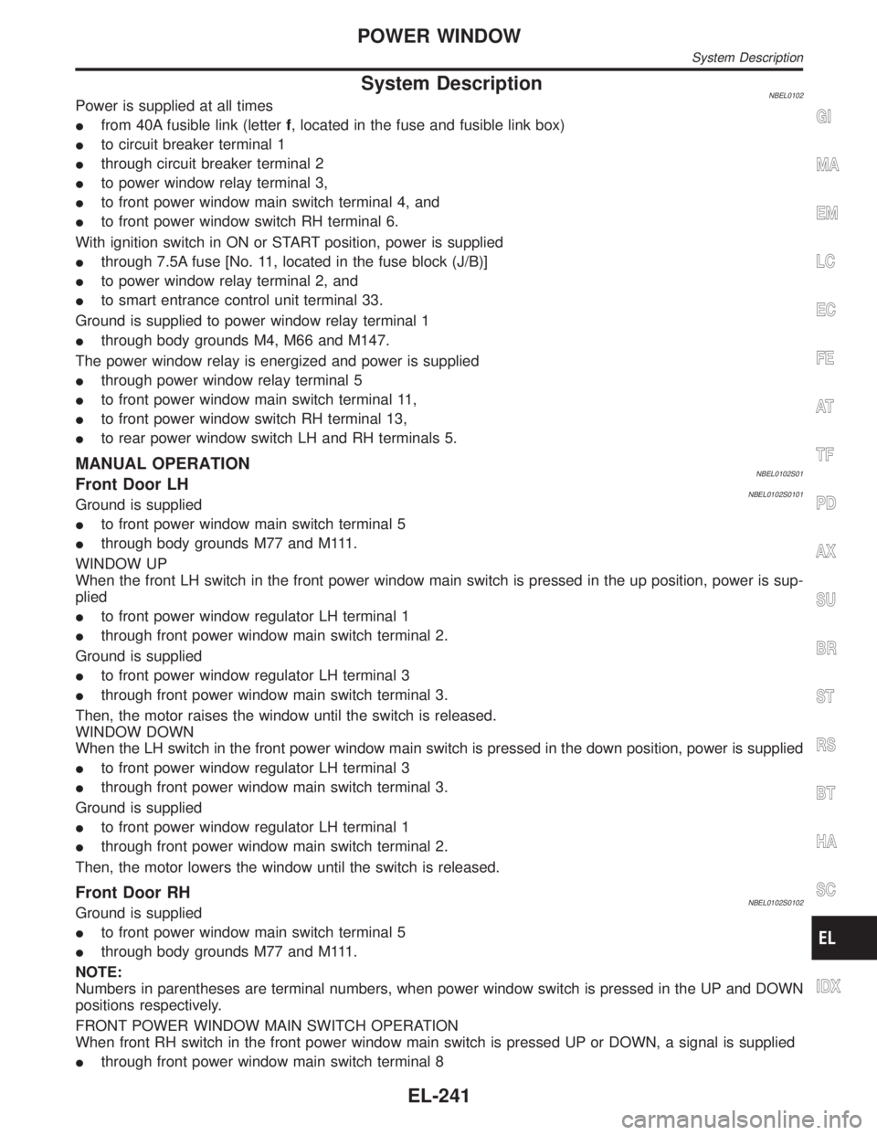
System DescriptionNBEL0102Power is supplied at all times
Ifrom 40A fusible link (letterf, located in the fuse and fusible link box)
Ito circuit breaker terminal 1
Ithrough circuit breaker terminal 2
Ito power window relay terminal 3,
Ito front power window main switch terminal 4, and
Ito front power window switch RH terminal 6.
With ignition switch in ON or START position, power is supplied
Ithrough 7.5A fuse [No. 11, located in the fuse block (J/B)]
Ito power window relay terminal 2, and
Ito smart entrance control unit terminal 33.
Ground is supplied to power window relay terminal 1
Ithrough body grounds M4, M66 and M147.
The power window relay is energized and power is supplied
Ithrough power window relay terminal 5
Ito front power window main switch terminal 11,
Ito front power window switch RH terminal 13,
Ito rear power window switch LH and RH terminals 5.
MANUAL OPERATIONNBEL0102S01Front Door LHNBEL0102S0101Ground is supplied
Ito front power window main switch terminal 5
Ithrough body grounds M77 and M111.
WINDOW UP
When the front LH switch in the front power window main switch is pressed in the up position, power is sup-
plied
Ito front power window regulator LH terminal 1
Ithrough front power window main switch terminal 2.
Ground is supplied
Ito front power window regulator LH terminal 3
Ithrough front power window main switch terminal 3.
Then, the motor raises the window until the switch is released.
WINDOW DOWN
When the LH switch in the front power window main switch is pressed in the down position, power is supplied
Ito front power window regulator LH terminal 3
Ithrough front power window main switch terminal 3.
Ground is supplied
Ito front power window regulator LH terminal 1
Ithrough front power window main switch terminal 2.
Then, the motor lowers the window until the switch is released.
Front Door RHNBEL0102S0102Ground is supplied
Ito front power window main switch terminal 5
Ithrough body grounds M77 and M111.
NOTE:
Numbers in parentheses are terminal numbers, when power window switch is pressed in the UP and DOWN
positions respectively.
FRONT POWER WINDOW MAIN SWITCH OPERATION
When front RH switch in the front power window main switch is pressed UP or DOWN, a signal is supplied
Ithrough front power window main switch terminal 8
GI
MA
EM
LC
EC
FE
AT
TF
PD
AX
SU
BR
ST
RS
BT
HA
SC
IDX
POWER WINDOW
System Description
EL-241
Page 1435 of 2395

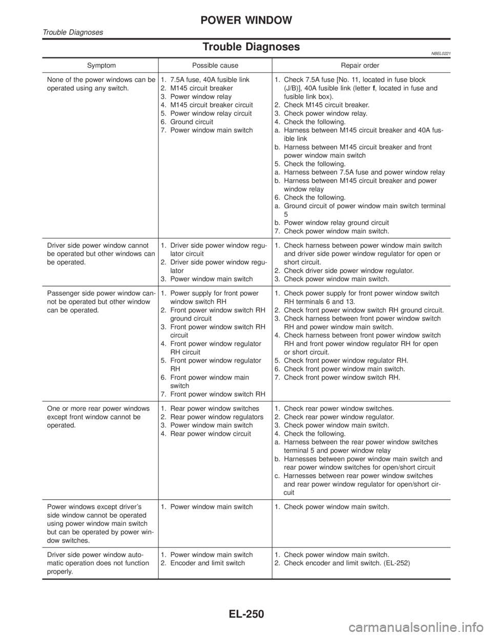
Trouble DiagnosesNBEL0221
Symptom Possible cause Repair order
None of the power windows can be
operated using any switch.1. 7.5A fuse, 40A fusible link
2. M145 circuit breaker
3. Power window relay
4. M145 circuit breaker circuit
5. Power window relay circuit
6. Ground circuit
7. Power window main switch1. Check 7.5A fuse [No. 11, located in fuse block
(J/B)], 40A fusible link (letterf, located in fuse and
fusible link box).
2. Check M145 circuit breaker.
3. Check power window relay.
4. Check the following.
a. Harness between M145 circuit breaker and 40A fus-
ible link
b. Harness between M145 circuit breaker and front
power window main switch
5. Check the following.
a. Harness between 7.5A fuse and power window relay
b. Harness between M145 circuit breaker and power
window relay
6. Check the following.
a. Ground circuit of power window main switch terminal
5
b. Power window relay ground circuit
7. Check power window main switch.
Driver side power window cannot
be operated but other windows can
be operated.1. Driver side power window regu-
lator circuit
2. Driver side power window regu-
lator
3. Power window main switch1. Check harness between power window main switch
and driver side power window regulator for open or
short circuit.
2. Check driver side power window regulator.
3. Check power window main switch.
Passenger side power window can-
not be operated but other window
can be operated.1. Power supply for front power
window switch RH
2. Front power window switch RH
ground circuit
3. Front power window switch RH
circuit
4. Front power window regulator
RH circuit
5. Front power window regulator
RH
6. Front power window main
switch
7. Front power window switch RH1. Check power supply for front power window switch
RH terminals 6 and 13.
2. Check front power window switch RH ground circuit.
3. Check harness between front power window switch
RH and power window main switch.
4. Check harness between front power window switch
RH and front power window regulator RH for open
or short circuit.
5. Check front power window regulator RH.
6. Check front power window main switch.
7. Check front power window switch RH.
One or more rear power windows
except front window cannot be
operated.1. Rear power window switches
2. Rear power window regulators
3. Power window main switch
4. Rear power window circuit1. Check rear power window switches.
2. Check rear power window regulator.
3. Check power window main switch.
4. Check the following.
a. Harness between the rear power window switches
terminal 5 and power window relay
b. Harnesses between power window main switch and
rear power window switches for open/short circuit
c. Harnesses between rear power window switches
and rear power window regulator for open/short cir-
cuit
Power windows except driver's
side window cannot be operated
using power window main switch
but can be operated by power win-
dow switches.1. Power window main switch 1. Check power window main switch.
Driver side power window auto-
matic operation does not function
properly.1. Power window main switch
2. Encoder and limit switch1. Check power window main switch.
2. Check encoder and limit switch. (EL-252)
POWER WINDOW
Trouble Diagnoses
EL-250
Page 1449 of 2395
KEY SWITCH (INSERT) CHECK=NBEL0110S06
1 CHECK KEY SWITCH INPUT SIGNAL
Check voltage between smart entrance control unit terminal 32 and ground.
SEL307X
Refer to wiring diagram in EL-257.
OK or NG
OK©Key switch is OK.
NG©GO TO 2.
2 CHECK KEY SWITCH (INSERT)
Check continuity between terminals 1 and 2.
SEL308X
OK or NG
OK©Check the following.
I7.5A fuse [No. 24, located in fuse block (J/B)]
IHarness for open or short between key switch and fuse
IHarness for open or short between smart entrance control unit and key switch
NG©Replace key switch.
POWER DOOR LOCK
Trouble Diagnoses (Cont'd)
EL-264
Page 1455 of 2395

Component Parts and Harness Connector
Location
NBEL0111
SEL355X
System DescriptionNBEL0112INPUTSNBEL0112S01Power is supplied at all times
Ito smart entrance control unit terminal 11
Ithrough circuit breaker
Ithrough 40A fusible link (letterflocated in the fuse and fusible link box),
Ito key switch terminal 2, and
Ito smart entrance control unit terminal 10
Ithrough 7.5A fuse [No. 24, located in the fuse block (J/B)].
Ito multi-remote control relay terminals 1, 3 and 6
Ithrough 15A fuse [No. 20, located in the fuse block (J/B)].
Ito horn relay terminals 1 and 3
Ithrough 7.5A fuse [No. 52, located in the fuse block (J/B)].
Ito horn relay terminal 6
Ithrough 10A fuse [No. 54, located in the fuse block (J/B)].
When the ignition switch is in the ACC or ON position, power is supplied to smart entrance control unit termi-
nal 21.
When the key switch is ON (ignition key is inserted in key cylinder), power is supplied
Ithrough key switch terminal 1
Ito smart entrance control unit terminal 32.
MULTI-REMOTE CONTROL SYSTEM
Component Parts and Harness Connector Location
EL-270
Page 1464 of 2395

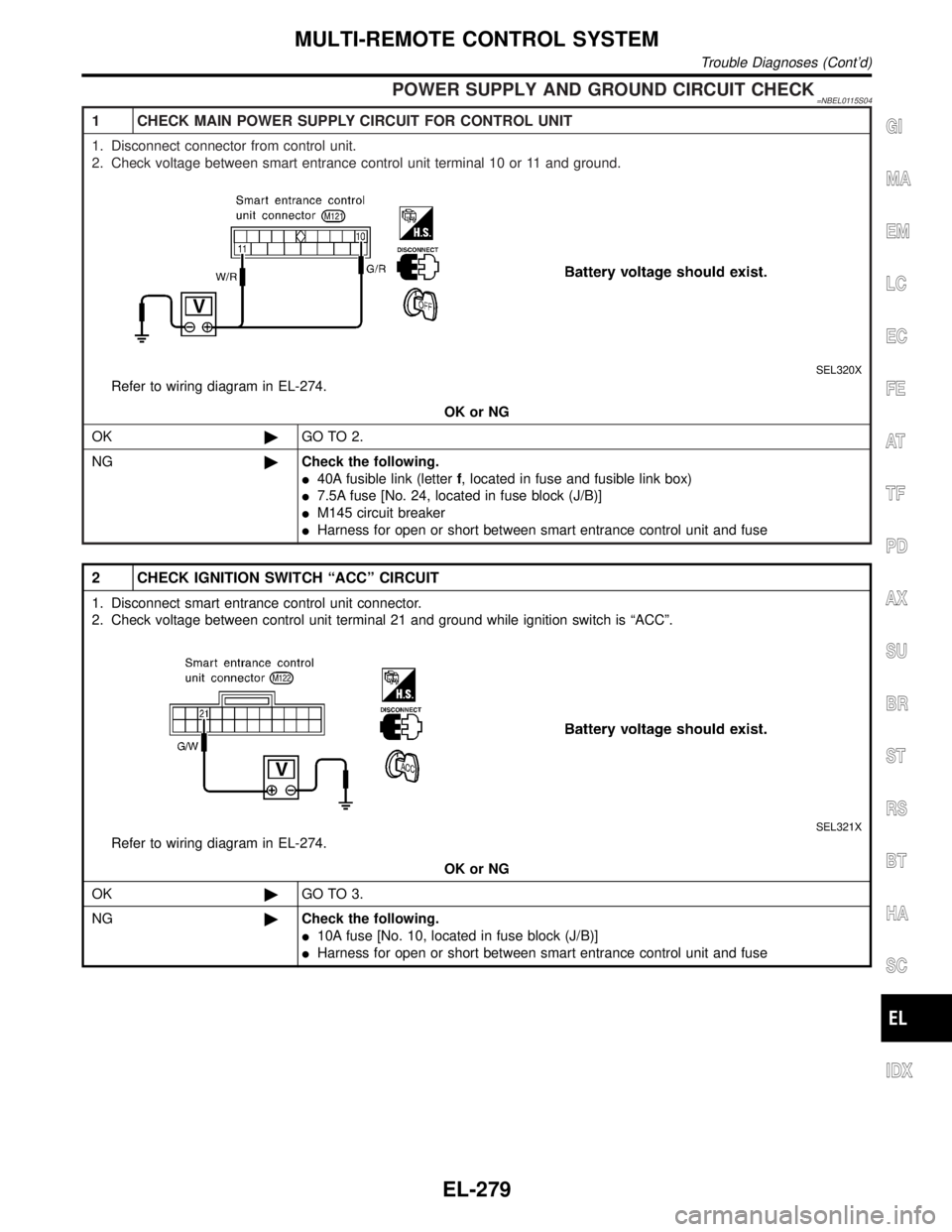
POWER SUPPLY AND GROUND CIRCUIT CHECK=NBEL0115S04
1 CHECK MAIN POWER SUPPLY CIRCUIT FOR CONTROL UNIT
1. Disconnect connector from control unit.
2. Check voltage between smart entrance control unit terminal 10 or 11 and ground.
SEL320X
Refer to wiring diagram in EL-274.
OK or NG
OK©GO TO 2.
NG©Check the following.
I40A fusible link (letterf, located in fuse and fusible link box)
I7.5A fuse [No. 24, located in fuse block (J/B)]
IM145 circuit breaker
IHarness for open or short between smart entrance control unit and fuse
2 CHECK IGNITION SWITCH ªACCº CIRCUIT
1. Disconnect smart entrance control unit connector.
2. Check voltage between control unit terminal 21 and ground while ignition switch is ªACCº.
SEL321X
Refer to wiring diagram in EL-274.
OK or NG
OK©GO TO 3.
NG©Check the following.
I10A fuse [No. 10, located in fuse block (J/B)]
IHarness for open or short between smart entrance control unit and fuse
GI
MA
EM
LC
EC
FE
AT
TF
PD
AX
SU
BR
ST
RS
BT
HA
SC
IDX
MULTI-REMOTE CONTROL SYSTEM
Trouble Diagnoses (Cont'd)
EL-279