2001 INFINITI QX4 fuse
[x] Cancel search: fusePage 1781 of 2395
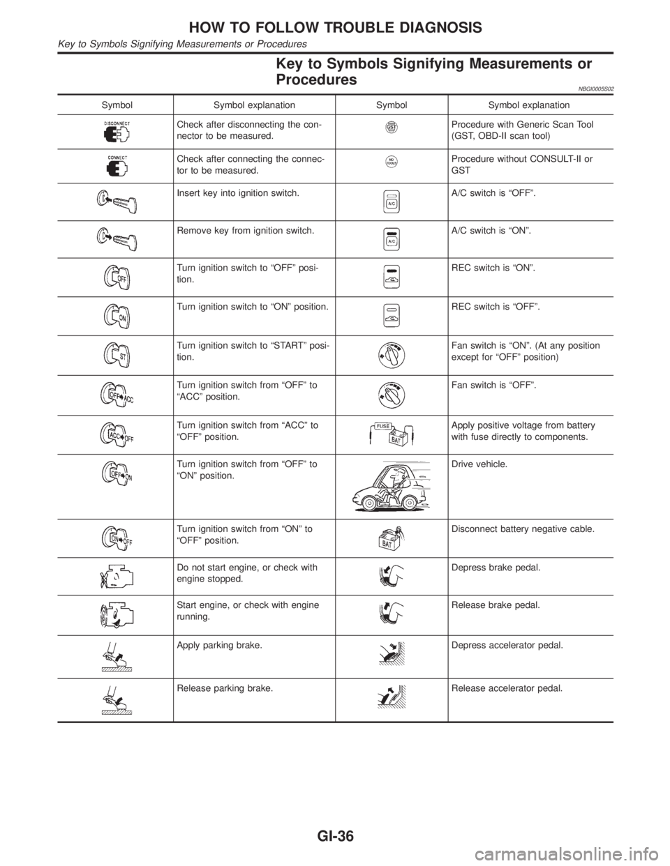
Key to Symbols Signifying Measurements or
Procedures
NBGI0005S02
Symbol Symbol explanation Symbol Symbol explanation
Check after disconnecting the con-
nector to be measured.Procedure with Generic Scan Tool
(GST, OBD-II scan tool)
Check after connecting the connec-
tor to be measured.Procedure without CONSULT-II or
GST
Insert key into ignition switch.A/C switch is ªOFFº.
Remove key from ignition switch.A/C switch is ªONº.
Turn ignition switch to ªOFFº posi-
tion.REC switch is ªONº.
Turn ignition switch to ªONº position.REC switch is ªOFFº.
Turn ignition switch to ªSTARTº posi-
tion.Fan switch is ªONº. (At any position
except for ªOFFº position)
Turn ignition switch from ªOFFº to
ªACCº position.Fan switch is ªOFFº.
Turn ignition switch from ªACCº to
ªOFFº position.Apply positive voltage from battery
with fuse directly to components.
Turn ignition switch from ªOFFº to
ªONº position.Drive vehicle.
Turn ignition switch from ªONº to
ªOFFº position.Disconnect battery negative cable.
Do not start engine, or check with
engine stopped.Depress brake pedal.
Start engine, or check with engine
running.Release brake pedal.
Apply parking brake.Depress accelerator pedal.
Release parking brake.Release accelerator pedal.
HOW TO FOLLOW TROUBLE DIAGNOSIS
Key to Symbols Signifying Measurements or Procedures
GI-36
Page 1804 of 2395
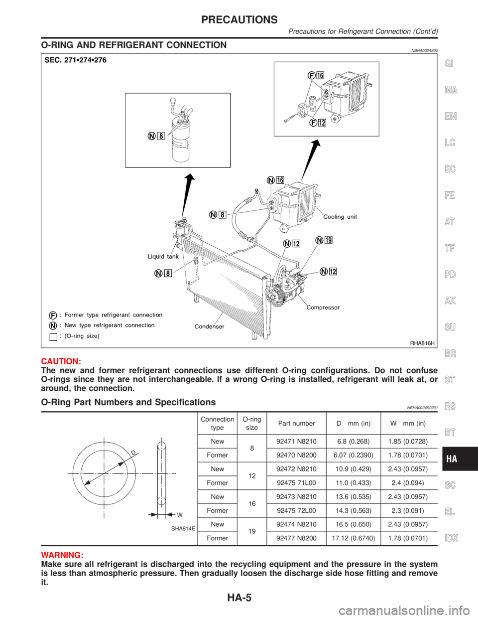
O-RING AND REFRIGERANT CONNECTIONNBHA0004S02
RHA816H
CAUTION:
The new and former refrigerant connections use different O-ring configurations. Do not confuse
O-rings since they are not interchangeable. If a wrong O-ring is installed, refrigerant will leak at, or
around, the connection.
O-Ring Part Numbers and SpecificationsNBHA0004S0201
SHA814E
Connection
typeO-ring
sizePart number D mm (in) W mm (in)
New
892471 N8210 6.8 (0.268) 1.85 (0.0728)
Former 92470 N8200 6.07 (0.2390) 1.78 (0.0701)
New
1292472 N8210 10.9 (0.429) 2.43 (0.0957)
Former 92475 71L00 11.0 (0.433) 2.4 (0.094)
New
1692473 N8210 13.6 (0.535) 2.43 (0.0957)
Former 92475 72L00 14.3 (0.563) 2.3 (0.091)
New
1992474 N8210 16.5 (0.650) 2.43 (0.0957)
Former 92477 N8200 17.12 (0.6740) 1.78 (0.0701)
WARNING:
Make sure all refrigerant is discharged into the recycling equipment and the pressure in the system
is less than atmospheric pressure. Then gradually loosen the discharge side hose fitting and remove
it.
GI
MA
EM
LC
EC
FE
AT
TF
PD
AX
SU
BR
ST
RS
BT
SC
EL
IDX
PRECAUTIONS
Precautions for Refrigerant Connection (Cont'd)
HA-5
Page 1873 of 2395

SHA967EE
RHA868H
Check body ground circuit for auto amp. with ignition switch OFF.
Check for continuity between terminal Nos. 32, 14 and body
ground.
Ohmmeter terminal
Continuity
(+) (þ)
32
Body ground Yes
14 (Canada only)
If OK, check auto amp. ground circuit, see below.
IIf NG, check 7.5A fuses (Nos. 11 and 24, located in the fuse
block) and 15A fuses (Nos. 1 and 2, located in the fuse block).
IIf fuses are OK, check for open circuit in wiring harness.
Repair or replace as necessary.
IIf fuses are NG, replace fuse and check wiring harness for
short circuit. Repair or replace as necessary.
NOTE:
If OK, replace auto amp.
If NG, repair or replace harness.
TROUBLE DIAGNOSES
A/C System (Cont'd)
HA-74
Page 1900 of 2395
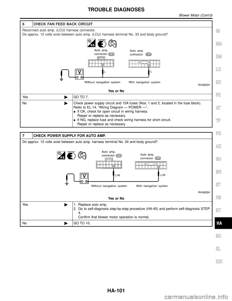
6 CHECK FAN FEED BACK CIRCUIT
Reconnect auto amp. (LCU) harness connector.
Do approx. 12 volts exist between auto amp. (LCU) harness terminal No. 33 and body ground?
RHA825H
YesorNo
Ye s©GO TO 7.
No©Check power supply circuit and 15A fuses (Nos. 1 and 2, located in the fuse block).
Refer to EL-14, ªWiring Diagram Ð POWER к.
IIf OK, check for open circuit in wiring harness.
Repair or replace as necessary.
IIf NG, replace fuse and check wiring harness for short circuit.
Repair or replace as necessary.
7 CHECK POWER SUPPLY FOR AUTO AMP.
Do approx. 12 volts exist between auto amp. harness terminal No. 34 and body ground?
RHA826H
YesorNo
Ye s©1. Replace auto amp.
2. Go to self-diagnosis step-by-step procedure (HA-45) and perform self-diagnosis STEP
4.
Confirm that blower motor operation is normal.
No©GO TO 10.
GI
MA
EM
LC
EC
FE
AT
TF
PD
AX
SU
BR
ST
RS
BT
SC
EL
IDX
TROUBLE DIAGNOSES
Blower Motor (Cont'd)
HA-101
Page 1901 of 2395
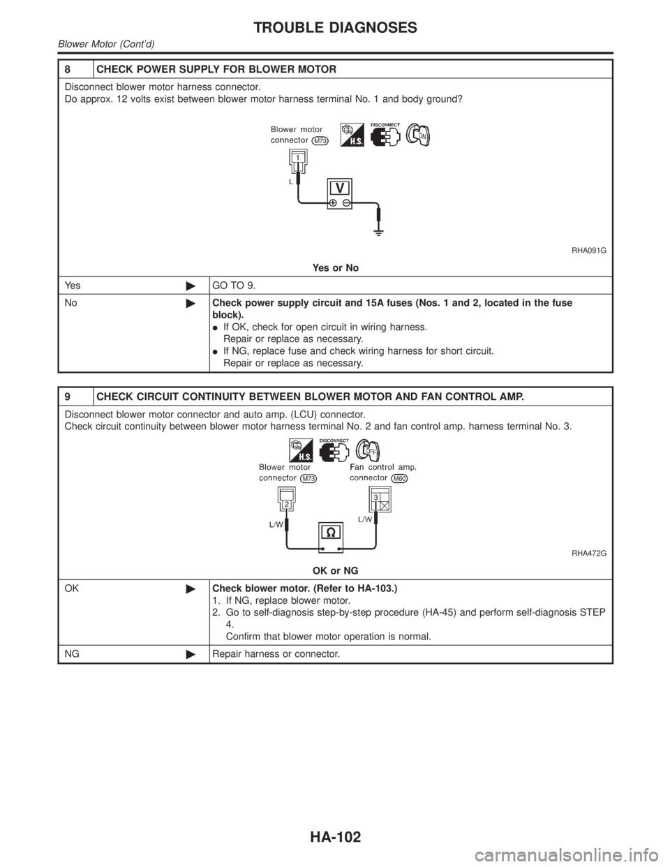
8 CHECK POWER SUPPLY FOR BLOWER MOTOR
Disconnect blower motor harness connector.
Do approx. 12 volts exist between blower motor harness terminal No. 1 and body ground?
RHA091G
YesorNo
Ye s©GO TO 9.
No©Check power supply circuit and 15A fuses (Nos. 1 and 2, located in the fuse
block).
IIf OK, check for open circuit in wiring harness.
Repair or replace as necessary.
IIf NG, replace fuse and check wiring harness for short circuit.
Repair or replace as necessary.
9 CHECK CIRCUIT CONTINUITY BETWEEN BLOWER MOTOR AND FAN CONTROL AMP.
Disconnect blower motor connector and auto amp. (LCU) connector.
Check circuit continuity between blower motor harness terminal No. 2 and fan control amp. harness terminal No. 3.
RHA472G
OK or NG
OK©Check blower motor. (Refer to HA-103.)
1. If NG, replace blower motor.
2. Go to self-diagnosis step-by-step procedure (HA-45) and perform self-diagnosis STEP
4.
Confirm that blower motor operation is normal.
NG©Repair harness or connector.
TROUBLE DIAGNOSES
Blower Motor (Cont'd)
HA-102
Page 1906 of 2395
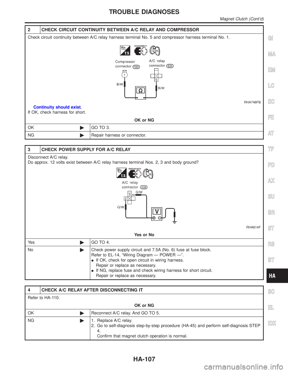
2 CHECK CIRCUIT CONTINUITY BETWEEN A/C RELAY AND COMPRESSOR
Check circuit continuity between A/C relay harness terminal No. 5 and compressor harness terminal No. 1.
RHA748FB
Continuity should exist.
If OK, check harness for short.
OK or NG
OK©GO TO 3.
NG©Repair harness or connector.
3 CHECK POWER SUPPLY FOR A/C RELAY
Disconnect A/C relay.
Do approx. 12 volts exist between A/C relay harness terminal Nos. 2, 3 and body ground?
RHA614F
YesorNo
Ye s©GO TO 4.
No©Check power supply circuit and 7.5A (No. 6) fuse at fuse block.
Refer to EL-14, ªWiring Diagram Ð POWER к.
IIf OK, check for open circuit in wiring harness.
Repair or replace as necessary.
IIf NG, replace fuse and check wiring harness for short circuit.
Repair or replace as necessary.
4 CHECK A/C RELAY AFTER DISCONNECTING IT
Refer to HA-110.
OK or NG
OK©Reconnect A/C relay. And GO TO 5.
NG©1. Replace A/C relay.
2. Go to self-diagnosis step-by-step procedure (HA-45) and perform self-diagnosis STEP
4.
Confirm that magnet clutch operation is normal.
GI
MA
EM
LC
EC
FE
AT
TF
PD
AX
SU
BR
ST
RS
BT
SC
EL
IDX
TROUBLE DIAGNOSES
Magnet Clutch (Cont'd)
HA-107
Page 1963 of 2395
E
ECM input/output signal ...............................EC-127
ECTS - Wiring diagram ........................EC-171, 189
Electric sun roof ............................................EL-173
Electrical diagnoses.........................................GI-24
Electrical ignition system ................................EC-30
Electrical unit ................................................Foldout
Electrical units location .................................EL-436
Engine compartment .......................................BT-58
Engine control circuit diagram........................EC-24
Engine control component parts
location .......................................................EC-20
Engine control module (ECM) ......................EC-444
Engine control system diagram and
chart ............................................................EC-25
Engine coolant temperature sensor
(ECTS) ..............................................EC-169, 187
Engine fail-safe system ................................EC-117
Engine oil filter replacement ..........................MA-18
Engine oil precautions .......................................GI-8
Engine oil replacement ..................................MA-18
Engine outer component parts ......................EM-10
Engine removal ..............................................EM-57
Engine room - See Engine
compartment................................................BT-58
Engine serial number ......................................GI-43
EVAP canister.................................................EC-33
EVAP canister purge volume control
solenoid valve.............................EC-32, 367, 541
EVAP canister vent control
valve .........................................EC-374, 553, 573
EVAP control system (small leak)
diagnosis ..................................EC-352, 394, 526
EVAP control system pressure sensor.........EC-381
EVAP control system purge flow moni-
toring diagnosis.........................................EC-561
EVAP vapor lines inspection ..........................MA-20
Evaporative emission (EVAP) system ............EC-32
Exhaust system ................................................FE-8
Exhaust system inspection ............................MA-21
Exterior ............................................................BT-35
F
4LO indicator lamp........................................TF-104
4WD shift indicator lamp.................................TF-98
4WD shift switch ............................................TF-111
4WD solenoid valve.......................................TF-111
4WD warning lamp .........................................TF-13
Fan control amp. ............................................HA-98
F/FOG - Wiring diagram .................................EL-72
Final drive disassembly ..................................PD-43
Final drive pre-inspection ...............................PD-43
Final drive removal and installation ...............PD-43
Finisher, interior - See Trim ............................BT-28
F/LID - Wiring diagram .................................EL-180
Fluid temperature sensor (A/T) .....................AT-110Fluids ..............................................................MA-11
Flywheel runout..............................................EM-70
FO2H-L - Wiring diagram .............................EC-243
FO2H-R - Wiring diagram ............................EC-242
Fog lamp, front................................................EL-70
Fog lamp, front, removal and
installation ...................................................BT-12
Forward clutch ...............................................AT-320
F/PUMP - Wiring diagram ............................EC-627
Freeze frame data ..........................................EC-60
FRO2LH - Wiring diagram ...........EC-197, 223, 235
FRO2RH - Wiring diagram...........EC-196, 222, 234
Front axle..........................................................AX-2
Front bumper ..................................................BT-12
Front case (Transfer) ....................................TF-133
Front combination lamp removal and
installation ...................................................BT-12
Front disc brake .............................................BR-22
Front door .......................................................BT-18
Front drive shaft (Transfer) ...........................TF-125
Front final drive disassembly (4WD) ..............PD-18
Front final drive pre-inspection (4WD) ...........PD-18
Front final drive removal and installa-
tion (4WD)...................................................PD-18
Front fog lamp.................................................EL-70
Front fog lamp removal and installation .........BT-12
Front heated oxygen sensor (HO2S)
(Left bank) ................EC-192, 202, 210, 218, 231
Front heated oxygen sensor (HO2S)
(Right bank) .............EC-192, 202, 210, 218, 231
Front heated oxygen sensor heater
(Left bank).................................................EC-240
Front heated oxygen sensor heater
(Right bank) ..............................................EC-240
Front revolution sensor (Transfer) ................TF-112
Front seat ........................................................BT-41
Front seat belt ..................................................RS-4
Front suspension ..............................................SU-2
Front washer .................................................EL-136
Front wiper ....................................................EL-136
Fuel cut control (at no load & high
engine speed) .............................................EC-32
Fuel filler lid.....................................................BT-15
Fuel filter replacement ...................................MA-16
Fuel gauge ......................................................EL-94
Fuel injection system (Left bank) .........EC-294, 302
Fuel injection system (Right bank) ......EC-294, 302
Fuel lid opener, electric.................................EL-180
Fuel line inspection ........................................MA-16
Fuel precautions ................................................GI-8
Fuel pressure check .......................................EC-39
Fuel pressure regulator ..................................EC-40
Fuel pressure release ....................................EC-39
Fuel pump ....................................................EC-625
Fuel system ......................................................FE-4
Fuel tank temperature sensor ......................EC-309
Fuel tank vacuum relief valve ........................EC-33
FUELLH - Wiring diagram....................EC-297, 305
FUELRH - Wiring diagram ...................EC-296, 304
Fuse ................................................................EL-16
Fuse block ....................................................Foldout
ALPHABETICAL INDEX
IDX-4
Page 2012 of 2395
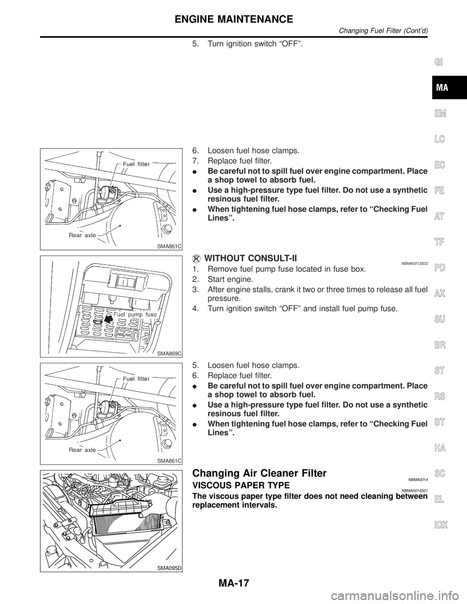
5. Turn ignition switch ªOFFº.
SMA861C
6. Loosen fuel hose clamps.
7. Replace fuel filter.
IBe careful not to spill fuel over engine compartment. Place
a shop towel to absorb fuel.
IUse a high-pressure type fuel filter. Do not use a synthetic
resinous fuel filter.
IWhen tightening fuel hose clamps, refer to ªChecking Fuel
Linesº.
SMA869C
WITHOUT CONSULT-IINBMA0013S021. Remove fuel pump fuse located in fuse box.
2. Start engine.
3. After engine stalls, crank it two or three times to release all fuel
pressure.
4. Turn ignition switch ªOFFº and install fuel pump fuse.
SMA861C
5. Loosen fuel hose clamps.
6. Replace fuel filter.
IBe careful not to spill fuel over engine compartment. Place
a shop towel to absorb fuel.
IUse a high-pressure type fuel filter. Do not use a synthetic
resinous fuel filter.
IWhen tightening fuel hose clamps, refer to ªChecking Fuel
Linesº.
SMA095D
Changing Air Cleaner FilterNBMA0014VISCOUS PAPER TYPENBMA0014S01The viscous paper type filter does not need cleaning between
replacement intervals.
GI
EM
LC
EC
FE
AT
TF
PD
AX
SU
BR
ST
RS
BT
HA
SC
EL
IDX
ENGINE MAINTENANCE
Changing Fuel Filter (Cont'd)
MA-17