Page 2046 of 2395
SPD670
9. Take out drive pinion together with rear bearing inner cone,
drive pinion bearing spacer and pinion bearing adjusting
washer.
10. Remove front oil seal and pinion front bearing inner cone.
PD349
11. Remove pinion bearing outer races with a brass drift.
SPD209
12. Remove pinion rear bearing inner cone and drive pinion height
adjusting washer.
Tool number: ST30031000 (J22912-01)
SPD207A
DIFFERENTIAL CASENBPD0018S031. Remove side bearing inner cones.
To prevent damage to bearing, engage puller jaws in grooves.
Tool number:
A ST33051001 (J22888-20)
B ST33061000 (J8107-2)
SPD022
Be careful not to confuse the right and left hand parts.
Keep bearing and bearing race for each side together.
GI
MA
EM
LC
EC
FE
AT
TF
AX
SU
BR
ST
RS
BT
HA
SC
EL
IDX
FRONT FINAL DRIVER200A
Disassembly (Cont'd)
PD-21
Page 2071 of 2395
SPD563
9. Remove front oil seal and pinion front bearing inner cone.
10. Remove pinion bearing outer races with a brass drift.
SPD018
11. Remove pinion rear bearing inner cone and drive pinion adjust-
ing washer.
Tool number: ST30031000 (J22912-01)
SPD207A
DIFFERENTIAL CASENBPD0033S031. Remove side bearing inner cones.
To prevent damage to bearing, engage puller jaws in
groove.
Tool number:
A ST33051001 (J22888-20)
B ST33061000 (J8107-2)
SPD022
Be careful not to confuse the left and right hand parts.
Keep bearing and bearing race for each side together.
SPD024
2. Loosen ring gear bolts in a criss-cross pattern.
3. Tap ring gear off differential case with a soft hammer.
Tap evenly all around to keep ring gear from binding.
REAR FINAL DRIVEH233B
Disassembly (Cont'd)
PD-46
Page 2121 of 2395
How to Perform Trouble Diagnoses for Quick
and Accurate Repair
=NBRS0041A good understanding of the malfunction conditions can make troubleshooting faster and more accurate.
In general, each customer feels differently about a malfunction. It is important to fully understand the symp-
toms or conditions for a customer complaint.
INFORMATION FROM CUSTOMERNBRS0041S01WHAT ..... Vehicle model
WHEN ..... Date, Frequencies
WHERE ..... Road conditions
HOW ..... Operating conditions, Symptoms
PRELIMINARY CHECKNBRS0041S02Check that the following parts are in good order.
IBattery [Refer to SC-4, ªBATTERYº.]
IFuse [Refer to EL-16, ªFuseº, ªPOWER SUPPLY ROUTINGº.]
ISystem component-to-harness connections
SUPPLEMENTAL RESTRAINT SYSTEM (SRS)
How to Perform Trouble Diagnoses for Quick and Accurate Repair
RS-32
Page 2127 of 2395

SRS800
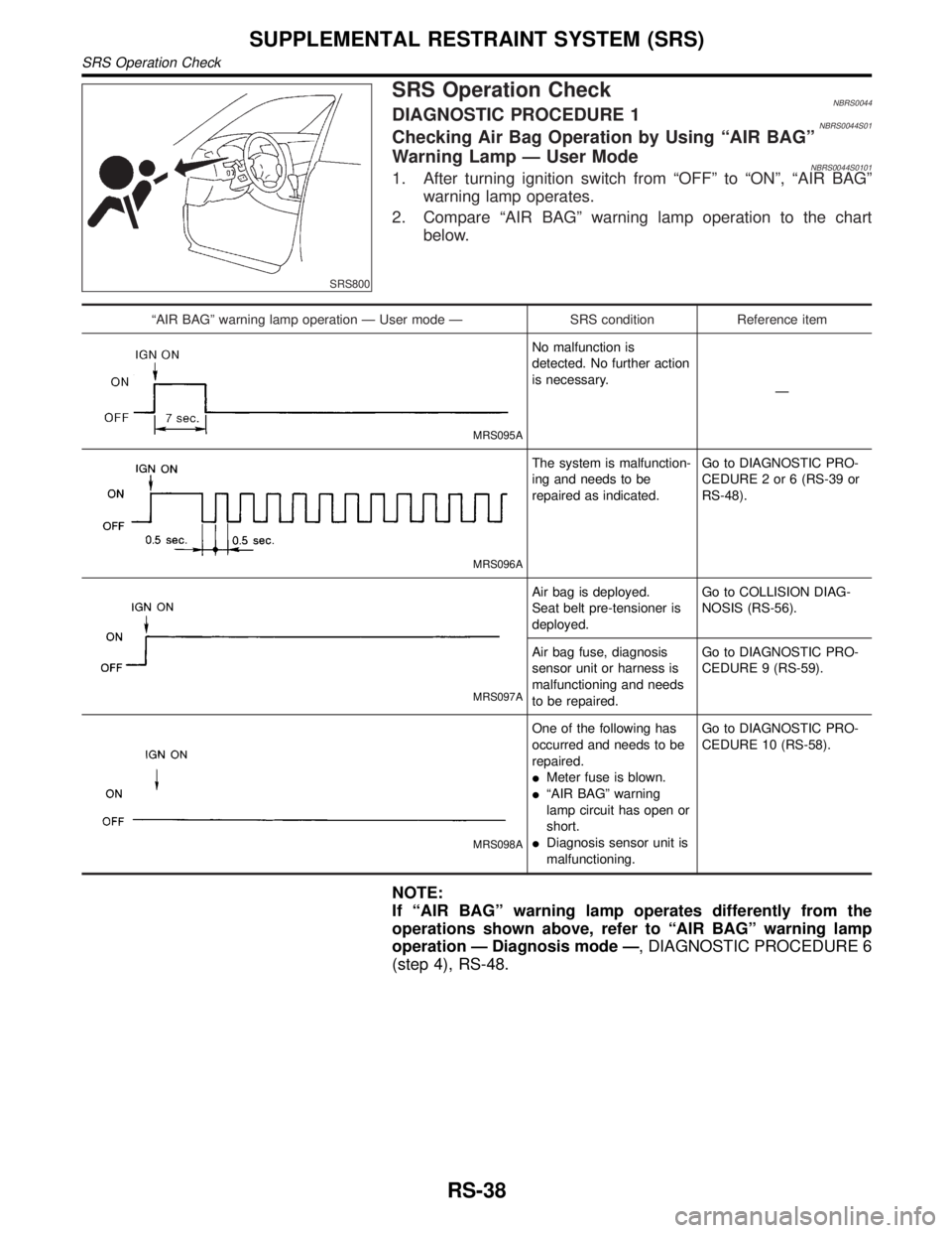
SRS Operation CheckNBRS0044DIAGNOSTIC PROCEDURE 1NBRS0044S01Checking Air Bag Operation by Using ªAIR BAGº
Warning Lamp Ð User Mode
NBRS0044S01011. After turning ignition switch from ªOFFº to ªONº, ªAIR BAGº
warning lamp operates.
2. Compare ªAIR BAGº warning lamp operation to the chart
below.
ªAIR BAGº warning lamp operation Ð User mode Ð SRS condition Reference item
MRS095A
No malfunction is
detected. No further action
is necessary.
Ð
MRS096A
The system is malfunction-
ing and needs to be
repaired as indicated.Go to DIAGNOSTIC PRO-
CEDURE 2 or 6 (RS-39 or
RS-48).
MRS097A
Air bag is deployed.
Seat belt pre-tensioner is
deployed.Go to COLLISION DIAG-
NOSIS (RS-56).
Air bag fuse, diagnosis
sensor unit or harness is
malfunctioning and needs
to be repaired.Go to DIAGNOSTIC PRO-
CEDURE 9 (RS-59).
MRS098A
One of the following has
occurred and needs to be
repaired.
IMeter fuse is blown.
IªAIR BAGº warning
lamp circuit has open or
short.
IDiagnosis sensor unit is
malfunctioning.Go to DIAGNOSTIC PRO-
CEDURE 10 (RS-58).
NOTE:
If ªAIR BAGº warning lamp operates differently from the
operations shown above, refer to ªAIR BAGº warning lamp
operation Ð Diagnosis mode Ð, DIAGNOSTIC PROCEDURE 6
(step 4), RS-48.
SUPPLEMENTAL RESTRAINT SYSTEM (SRS)
SRS Operation Check
RS-38
Page 2144 of 2395

ªAIR BAGº warning lamp operation Ð User mode Ð SRS condition Reference item
MRS095A
No malfunction is
detected.
No further action is neces-
sary.Ð
MRS096A
The system is malfunction-
ing and needs to be
repaired as indicated.Go to DIAGNOSTIC PRO-
CEDURE 6 (RS-48).
MRS097A
Air bag is deployed.
Seat belt pre-tensioner is
deployed.Go to COLLISION DIAG-
NOSIS (RS-59).
Air bag fuse, diagnosis
sensor unit or harness is
malfunctioning and needs
to be repaired.Go to DIAGNOSTIC PRO-
CEDURE 9 RS-56).
MRS098A
One of the following has
occurred and needs to be
repaired.
IMeter fuse is blown.
IªAIR BAGº warning
lamp circuit has open or
short.
IDiagnosis sensor unit is
malfunctioning.Go to DIAGNOSTIC PRO-
CEDURE 10 (RS-58).
DIAGNOSTIC PROCEDURE 8 (CONTINUED FROM
DIAGNOSTIC PROCEDURE 6)
NBRS0046S03Inspecting SRS malfunctioning record
1 CONSIDER POSSIBILITY OF NOT ERASING SELF-DIAGNOSTIC RESULT AFTER REPAIRING
Is it the first time for maintenance of SRS?
YesorNo
Ye s©Go to DIAGNOSTIC PROCEDURE 5 (RS-44). (Further inspection cannot be performed
without CONSULT-II.)
No©Diagnosis results (previously stored in the memory) might not be erased after repair. Go
to DIAGNOSTIC PROCEDURE 7, step 5 (RS-53).
GI
MA
EM
LC
EC
FE
AT
TF
PD
AX
SU
BR
ST
BT
HA
SC
EL
IDX
SUPPLEMENTAL RESTRAINT SYSTEM (SRS)
Trouble Diagnoses without CONSULT-II (Cont'd)
RS-55
Page 2145 of 2395
Trouble Diagnoses: ªAIR BAGº Warning Lamp
Does Not Turn Off
=NBRS0047DIAGNOSTIC PROCEDURE 9NBRS0047S01
1 SEE THE DEPLOYMENT OF AIR BAG MODULE
Is air bag module deployed?
YesorNo
Ye s©Refer to COLLISION DIAGNOSIS (RS-59).
No©GO TO 2.
2 CHECK AIR BAG FUSE
Is SRS ªAir Bagº fuse OK?
SRS577
OK or NG
OK©GO TO 4.
NG©GO TO 3.
3 CHECK AIR BAG FUSE AGAIN
Replace ªAIR BAGº fuse and turn ignition switch ON.
Is ªAIR BAGº fuse blown again?
Ye s©Repair main harness and/or replace air bag harness.
No©INSPECTION END
SUPPLEMENTAL RESTRAINT SYSTEM (SRS)
Trouble Diagnoses: ªAIR BAGº Warning Lamp Does Not Turn Off
RS-56
Page 2147 of 2395
Trouble Diagnoses: ªAIR BAGº Warning Lamp
Does Not Turn On
=NBRS0048DIAGNOSTIC PROCEDURE 10NBRS0048S01
1 CHECK ªMETERº FUSE
Is meter fuse OK?
SRS852
OK or NG
OK©GO TO 3.
NG©GO TO 2.
2 CHECK ªMETERº FUSE AGAIN
Replace meter fuse and turn ignition switch ON.
Is meter fuse blown again?
Ye s©Repair main harness.
No©INSPECTION END
3 CHECK ªAIR BAGº WARNING LAMP LED
Is ªAIR BAGº warning lamp LED OK?
OK or NG
OK©GO TO 4.
NG©Replace ªAIR BAGº warning lamp LED.
4 CHECK HARNESS CONNECTION BETWEEN DIAGNOSIS SENSOR UNIT AND ªAIR BAGº WARNING
LAMP
Disconnect diagnosis sensor unit connector and turn ignition switch ªONº.
IDoes ªAIR BAGº warning lamp turn on?
YesorNo
Ye s©Replace diagnosis sensor unit.
No©Check the ground circuit of ªAIR BAGº warning lamp.
SUPPLEMENTAL RESTRAINT SYSTEM (SRS)
Trouble Diagnoses: ªAIR BAGº Warning Lamp Does Not Turn On
RS-58
Page 2161 of 2395

System DescriptionNBSC0004Power is supplied at all times
Ito ignition switch terminal 1
Ithrough 40A fusible link (lettere, located in the fuse and fusible link box).
With the ignition switch in the ON or START position, power is supplied through 10A fuse [No. 18, located in
the fuse block (J/B)].
Ito park/neutral position relay terminal 1.
Also, with the ignition switch in the START position, power is supplied
Ifrom ignition switch terminal 5
Ito park/neutral position relay terminal 6.
With the selector lever in the P or N position, ground is supplied
Ito park/neutral position relay terminal 2 through the park/neutral position switch.
Then park/neutral position relay is energized and power is supplied
Ifrom park/neutral position relay terminal 7
Ito terminal 2 of the starter motor windings.
The starter motor plunger closes and provides a closed circuit between the battery and starter motor. The
starter motor is grounded to the engine block. With power and ground supplied, cranking occurs and the engine
starts.
STARTING SYSTEM
System Description
SC-10