2001 INFINITI QX4 transmission
[x] Cancel search: transmissionPage 357 of 2395

SAT001B
7. Install turbine revolution sensor.
8. Adjust brake band.
a. Tighten anchor end bolt to specified torque.
Anchor end bolt:
:4-6N´m(0.4 - 0.6 kg-m, 35 - 52 in-lb)
b. Back off anchor end bolt two and a half turns.
SAT002B
c. While holding anchor end bolt, tighten lock nut.
Ancher end bolt nut:
: 41 - 50 N´m (4.1 - 5.2 kg-m, 30 - 37 ft-lb)
SAT115B
9. Install terminal cord assembly.
a. Install O-ring on terminal cord assembly.
IApply petroleum jelly to O-ring.
b. Compress terminal cord assembly stopper and install terminal
cord assembly on transmission case.
SAT004BA
10. Install control valve assembly.
a. Install accumulator piston return springs B, C and D.
Free length of return springs:
Refer to SDS, AT-357.
SAT005B
b. Install manual valve on control valve.
IApply ATF to manual valve.
ASSEMBLY
Assembly (2) (Cont'd)
AT-352
Page 358 of 2395

SAT006B
c. Place control valve assembly on transmission case. Connect
solenoid connector for upper body.
d. Install connector clip.
SAT353B
e. Install control valve assembly on transmission case.
f. Install connector tube brackets and tighten bolts A and B.
ICheck that terminal assembly does not catch.
Bolt symbolmm (in)
A 33 (1.30)
B 45 (1.77)
SAT221B
g. Install O-ring on oil strainer.
IApply petroleum jelly to O-ring.
h. Install oil strainer on control valve.
SAT009B
i. Securely fasten terminal harness with clips.
GI
MA
EM
LC
EC
FE
TF
PD
AX
SU
BR
ST
RS
BT
HA
SC
EL
IDX
ASSEMBLY
Assembly (2) (Cont'd)
AT-353
Page 359 of 2395

SAT010B
j. Install torque converter clutch solenoid valve and A/T fluid tem-
perature sensor connectors.
SAT011B
11. Install oil pan.
a. Attach a magnet to oil pan.
SAT365I
b. Install new oil pan gasket on transmission case.
c. Install oil pan and bracket on transmission case.
IAlways replace oil pan bolts as they are self-sealing bolts.
IBefore installing bolts, remove traces of sealant and oil
from mating surface and thread holes.
ITighten four bolts in a criss-cross pattern to prevent dis-
location of gasket.
d. Tighten drain plug.
SAT299I
12. Install PNP switch.
a. Check that manual shaft is in ª1º position.
b. Temporarily install PNP switch on manual shaft.
c. Move manual shaft to ªNº.
SAT014B
d. Tighten bolts while inserting 4.0 mm (0.157 in) dia. pin verti-
cally into locating holes in PNP switch and manual shaft.
ASSEMBLY
Assembly (2) (Cont'd)
AT-354
Page 361 of 2395

General SpecificationsNBAT0160
Applied modelVQ35DE engine
2WD 4WD
Automatic transmission model RE4R01A
Transmission model code number 4EX16 4EX17
Stall torque ratio2.0:1
Transmission gear ratio1st 2.785
2nd 1.545
Top 1.000
OD 0.694
Reverse 2.272
Recommended fluidNissan Matic ªDº (Continental U.S. and Alaska) or Genuine Nissan Automatic Trans-
mission Fluid (Canada)*1
Fluid capacity8.5(9 US qt, 7-1/2 Imp qt)
*1: Refer to MA-11, ªFluids and Lubricantsº.
Shift ScheduleNBAT0178VEHICLE SPEED WHEN SHIFTING GEARS THROTTLE POSITIONNBAT0178S01
Throttle positionVehicle speed km/h (MPH)
D
1,D2D2,D3D3,D4D4,D3D3,D2D2,D112,11
Full throttle55-59
(34 - 37)105 - 113
(65 - 70)174 - 184
(108 - 114)170 - 180
(106 - 112)102 - 110
(63 - 68)43-47
(27 - 29)43-47
(27 - 29)
Half throttle37-41
(23 - 25)71-79
(44 - 49)129 - 139
(80 - 86)81-91
(50 - 57)33-41
(21 - 25)12-16
(7 - 10)43-47
(27 - 29)
VEHICLE SPEED WHEN PERFORMING AND RELEASING LOCK-UPNBAT0178S02
Throttle positionOverdrive control switch [Shift posi-
tion]Vehicle speed km/h (MPH)
Lock-up ªONº Lock-up ªOFFº
Full throttleON [D
4] 174 - 184 (108 - 114) 170 - 180 (106 - 112)
OFF [D
3] 104 - 114 (65 - 71) 101 - 111 (63 - 69)
Half throttleON [D
4] 151 - 161 (94 - 100) 106 - 116 (66 - 72)
OFF [D
3] 85-95(53-59) 82-92(51-57)
Stall RevolutionNBAT0163
Stall revolution rpm2,440 - 2,640
Line PressureNBAT0164
Engine speed
rpmLine pressure kPa (kg/cm2, psi)
D, 2 and 1 positions R position
Idle 422 - 461 (4.3 - 4.7, 61 - 67) 667 - 706 (6.8 - 7.2, 97 - 102)
Stall 1,020 - 1,098 (10.4 - 11.2, 148 - 159) 1,422 - 1,500 (14.5 - 15.3, 206 - 218)
SERVICE DATA AND SPECIFICATIONS (SDS)
General Specifications
AT-356
Page 472 of 2395

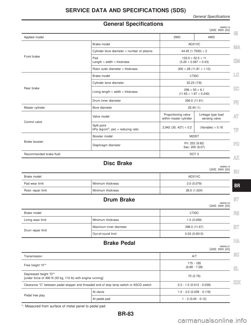
General SpecificationsNBBR0118Unit: mm (in)
Applied model2WD 4WD
Front brakeBrake model AD31VC
Cylinder bore diameter´number of pistons 44.45 (1.7500)´2
Pad
Length´width´thickness132.0´52.5´11
(5.20´2.067´0.43)
Rotor outer diameter´thickness 300´28 (11.81´1.10)
Rear brakeBrake model LT30C
Cylinder bore diameter 22.23 (7/8)
Lining length´width´thickness296´50´6.1
(11.65´1.97´0.240)
Drum inner diameter 295.0 (11.61)
Master cylinder Bore diameter 25.40 (1)
Control valveValve modelProportioning valve
within master cylinderLinkage type load
sensing valve
Split point
kPa (kg/cm
2, psi)´reducing ratio2,942 (30, 427)´0.2 (Variable)´0.18
Brake boosterBooster model M235T
Diaphragm diameterPri: 252 (9.92)
Sec: 205 (8.07)
Recommended brake fluidDOT 3
Disc BrakeNBBR0119Unit: mm (in)
Brake modelAD31VC
Pad wear limit Minimum thickness 2.0 (0.079)
Rotor repair limit Minimum thickness 26.0 (1.024)
Drum BrakeNBBR0120Unit: mm (in)
Brake modelLT30C
Lining wear limit Minimum thickness 1.5 (0.059)
Drum repair limitMaximum inner diameter 296.5 (11.67)
Out-of-round limit 0.03 (0.0012)
Brake PedalNBBR0121Unit: mm (in)
TransmissionA/T
Free height ªHº*175 - 185
(6.89 - 7.28)
Depressed height ªDº*
[under force of 490 N (50 kg, 110 lb) with engine running]70 (2.76)
Clearance ªCº between pedal stopper and threaded end of stop lamp switch or ASCD switch 0.3 - 1.0 (0.012 - 0.039)
Pedal free playAt clevis 1.0 - 3.0 (0.039 - 0.118)
At pedal pad1 - 3 (0.04 - 0.12)
*: Measured from surface of metal panel to pedal pad
GI
MA
EM
LC
EC
FE
AT
TF
PD
AX
SU
ST
RS
BT
HA
SC
EL
IDX
SERVICE DATA AND SPECIFICATIONS (SDS)
General Specifications
BR-83
Page 549 of 2395

Supplemental Restraint System (SRS) ªAIR
BAGº and ªSEAT BELT PRE-TENSIONERº
NBEC0002The Supplemental Restraint System such as ªAIR BAGº and ªSEAT BELT PRE-TENSIONERº used along with
a seat belt, helps to reduce the risk or severity of injury to the driver and front passenger for certain types of
collision. The SRS system composition which is available to INFINITI QX4 is as follows:
IFor a frontal collision
The Supplemental Restraint System consists of driver air bag module (located in the center of the steer-
ing wheel), front passenger air bag module (located on the instrument panel on passenger side), seat belt
pre-tensioners, a diagnosis sensor unit, warning lamp, wiring harness and spiral cable.
IFor a side collision
The Supplemental Restraint System consists of front side air bag module (located in the outer side of front
seat), satellite sensor, diagnosis sensor unit (one of components of air bags for a frontal collision), wiring
harness, warning lamp (one of components of air bags for a frontal collision).
Information necessary to service the system safely is included in theRS sectionof this Service Manual.
WARNING:
ITo avoid rendering the SRS inoperative, which could increase the risk of personal injury or death
in the event of a collision which would result in air bag inflation, all maintenance must be performed
by an authorized INFINITI dealer.
IImproper maintenance, including incorrect removal and installation of the SRS, can lead to per-
sonal injury caused by unintentional activation of the system. For removal of Spiral Cable and Air
Bag Module, see the RS section.
IDo not use electrical test equipment on any circuit related to the SRS unless instructed to in this
Service Manual. Spiral cable and wiring harnesses covered with yellow insulation tape either just
before the harness connectors or for the complete harness are related to the SRS.
Precautions for On Board Diagnostic (OBD)
System of Engine and A/T
NBEC0003The ECM has an on board diagnostic system. It will light up the malfunction indicator lamp (MIL) to warn the
driver of a malfunction causing emission deterioration.
CAUTION:
IBe sure to turn the ignition switch OFF and disconnect the negative battery terminal before any
repair or inspection work. The open/short circuit of related switches, sensors, solenoid valves, etc.
will cause the MIL to light up.
IBe sure to connect and lock the connectors securely after work. A loose (unlocked) connector will
cause the MIL to light up due to the open circuit. (Be sure the connector is free from water, grease,
dirt, bent terminals, etc.)
ICertain systems and components, especially those related to OBD, may use a new style slide-
locking type harness connector. For description and how to disconnect, refer to EL-6, ªHARNESS
CONNECTOR (SLIDE-LOCKING TYPE)º.
IBe sure to route and secure the harnesses properly after work. The interference of the harness with
a bracket, etc. may cause the MIL to light up due to the short circuit.
IBe sure to connect rubber tubes properly after work. A misconnected or disconnected rubber tube
may cause the MIL to light up due to the malfunction of the fuel injection system, etc.
IBe sure to erase the unnecessary malfunction information (repairs completed) from the ECM and
TCM (Transmission control module) before returning the vehicle to the customer.
PRECAUTIONS
Supplemental Restraint System (SRS) ªAIR BAGº and ªSEAT BELT PRE-TENSIONERº
EC-14
Page 562 of 2395

System ChartNBEC0013
Input (Sensor) ECM Function Output (Actuator)
ICamshaft position sensor (PHASE)
ICrankshaft position sensor (REF)
IMass air flow sensor
IEngine coolant temperature sensor
IHeated oxygen sensor 1 (front)
IIgnition switch
IThrottle position sensor
IClosed throttle position switch*3
IPark/neutral position (PNP) switch
IAir conditioner switch
IKnock sensor
IIntake air temperature sensor
IAbsolute pressure sensor
IEVAP control system pressure sensor*1
IBattery voltage
IPower steering oil pressure switch
IVehicle speed sensor
IFuel tank temperature sensor*1
ICrankshaft position sensor (POS)
IHeated oxygen sensor 2 (rear)*2
ITCM (Transmission control module)
IRefrigerant pressure sensor
IElectrical load
IFuel level sensor*1Fuel injection & mixture ratio control Injectors
Electronic ignition system Power transistor
Idle air control system IACV-AAC valve
Fuel pump control Fuel pump relay
On board diagnostic system MIL (On the instrument panel)
Swirl control valve controlSwirl control valve control solenoid
valve
Power valve control VIAS control solenoid valve
Heated oxygen sensor 1 heater (front) con-
trolHeated oxygen sensor 1 heater
(front)
Heated oxygen sensor 2 heater (rear) controlHeated oxygen sensor 2 heater
(rear)
EVAP canister purge flow controlEVAP canister purge volume con-
trol solenoid valve
Air conditioning cut control Air conditioner relay
ON BOARD DIAGNOSIS for EVAP systemIEVAP canister vent control valve
IVacuum cut valve bypass valve
*1: These sensors are not used to control the engine system. They are used only for the on board diagnosis.
*2: This sensor is not used to control the engine system under normal conditions.
*3: This switch will operate in place of the throttle position sensor to control EVAP parts if the sensor malfunctions.GI
MA
EM
LC
FE
AT
TF
PD
AX
SU
BR
ST
RS
BT
HA
SC
EL
IDX
ENGINE AND EMISSION CONTROL OVERALL SYSTEM
System Chart
EC-27
Page 579 of 2395

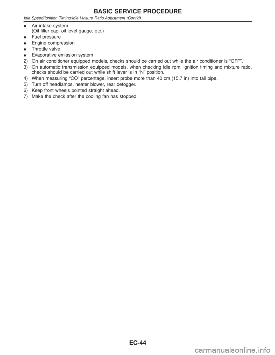
IAir intake system
(Oil filler cap, oil level gauge, etc.)
IFuel pressure
IEngine compression
IThrottle valve
IEvaporative emission system
2) On air conditioner equipped models, checks should be carried out while the air conditioner is ªOFFº.
3) On automatic transmission equipped models, when checking idle rpm, ignition timing and mixture ratio,
checks should be carried out while shift lever is in ªNº position.
4) When measuring ªCOº percentage, insert probe more than 40 cm (15.7 in) into tail pipe.
5) Turn off headlamps, heater blower, rear defogger.
6) Keep front wheels pointed straight ahead.
7) Make the check after the cooling fan has stopped.
BASIC SERVICE PROCEDURE
Idle Speed/Ignition Timing/Idle Mixture Ratio Adjustment (Cont'd)
EC-44