Page 177 of 2395

SAT341H
DescriptionNBAT0063Shift solenoid valves A and B are turned ªONº or ªOFFº by the TCM
in response to signals sent from the PNP switch, vehicle speed and
throttle position sensors. Gears will then be shifted to the optimum
position.
Gear position1234
Shift solenoid valve A ON (Closed) OFF (Open) OFF (Open) ON (Closed)
Shift solenoid valve B ON (Closed) ON (Closed) OFF (Open) OFF (Open)
TCM TERMINALS AND REFERENCE VALUENBAT0063S02Remarks: Specification data are reference values.
Terminal
No.Wire color Item ConditionJudgement
standard
(Approx.)
12 L/RShift solenoid
valve B
When shift solenoid valve B operates.
(When driving in ªD
1ºorªD2º.)Battery volt-
age
When shift solenoid valve B does not operate.
(When driving in ªD
3ºorªD4º.)0V
ON BOARD DIAGNOSIS LOGICNBAT0063S03
Diagnostic trouble code Malfunction is detected when ... Check item (Possible cause)
: SFT SOL B/CIRC TCM detects an improper voltage drop
when it tires to operate the solenoid
valve.IHarness or connectors
(The solenoid circuit is open or shorted.)
IShift solenoid valve B
: P0755
SAT014K
SAT020K
DIAGNOSTIC TROUBLE CODE (DTC) CONFIRMATION
PROCEDURE
NBAT0063S01CAUTION:
Always drive vehicle at a safe speed.
NOTE:
If ªDIAGNOSTIC TROUBLE CODE CONFIRMATION PROCE-
DUREº has been previously conducted, always turn ignition
switch ªOFFº and wait at least 5 seconds before conducting
the next test.
After the repair, perform the following procedure to confirm the
malfunction is eliminated.
With CONSULT-II
1) Turn ignition switch ªONº and select ªDATA MONITORº mode
for ªENGINEº with CONSULT-II.
2) Drive vehicle in ªDº position and allow the transmission to shift
1,2,3 (ªGEARº).
With GST
Follow the procedure ªWith CONSULT-IIº.
DTC P0755 SHIFT SOLENOID VALVE B
Description
AT-172
Page 207 of 2395

SAT136K
DescriptionNBAT0224The turbine revolution sensor detects input shaft rpm (revolutions
per minute). It is located on the input side of the automatic trans-
mission. The vehicle speed sensor A/T (Revolution sensor) is
located on the output side of the automatic transmission. With the
two sensors, input and output shaft rpms are accurately detected.
The result is optimal shift timing during deceleration and improved
shifting.
TCM TERMINALS AND REFERENCE VALUENBAT0224S01Remarks: Specification data are reference values.
Terminal
No.Wire color Item ConditionJudgement
standard
(Approx.)
38 WTurbine revolution
sensor
(Measure in AC
range)
When engine is running at 1,000 rpm1.2V
Voltage rises
gradually in
response to
engine speed.
42 BThrottle position
sensor (Ground)
Ð0V
ON BOARD DIAGNOSIS LOGICNBAT0224S02
Diagnostic trouble code Malfunction is detected when ... Check item (Possible cause)
: TURBINE REV
TCM does not receive the proper voltage
signal from the sensor.IHarness or connectors
(The sensor circuit is open or shorted.)
ITurbine revolution sensor
: 10th judgement flicker
DTC TURBINE REVOLUTION SENSOR
Description
AT-202
Page 262 of 2395

SAT136K
21. TCM Self-diagnosis Does Not Activate (PNP,
Overdrive Control and Throttle Position
Switches Circuit Checks)
NBAT0204
SAT143K
SAT142K
SYMPTOM:
O/D OFF indicator lamp does not come on in TCM self-diag-
nostic procedure even the lamp circuit is good.
DESCRIPTIONNBAT0204S01IPNP switch
The PNP switch assemble includes a transmission range
switch. The transmission range switch detects the selector
position and sends a signal to the TCM.
IOverdrive control switch
Detects the overdrive control switch position (ON or OFF) and
sends a signal to the TCM.
IThrottle position switch
Consists of a wide open throttle position switch and a closed
throttle position switch.
The wide open throttle position switch sends a signal to the
TCM when the throttle valve is open at least 1/2 of the full
throttle position. The closed throttle position switch sends a
signal to the TCM when the throttle valve is fully closed.
GI
MA
EM
LC
EC
FE
TF
PD
AX
SU
BR
ST
RS
BT
HA
SC
EL
IDX
TROUBLE DIAGNOSES FOR SYMPTOMS
21. TCM Self-diagnosis Does Not Activate (PNP, Overdrive Control and Throttle Position Switches Circuit Checks)
AT-257
Page 280 of 2395

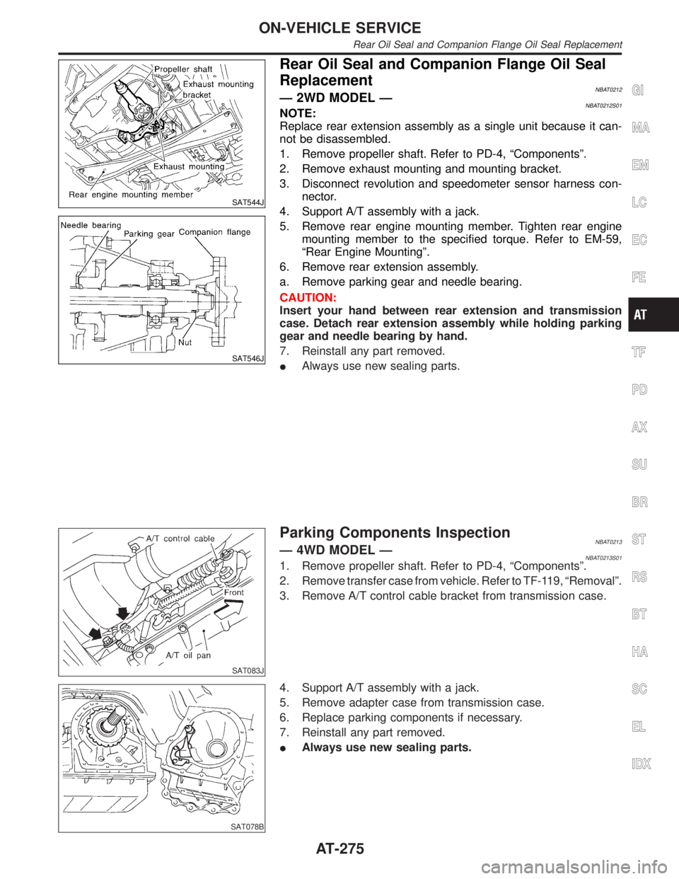
SAT544J
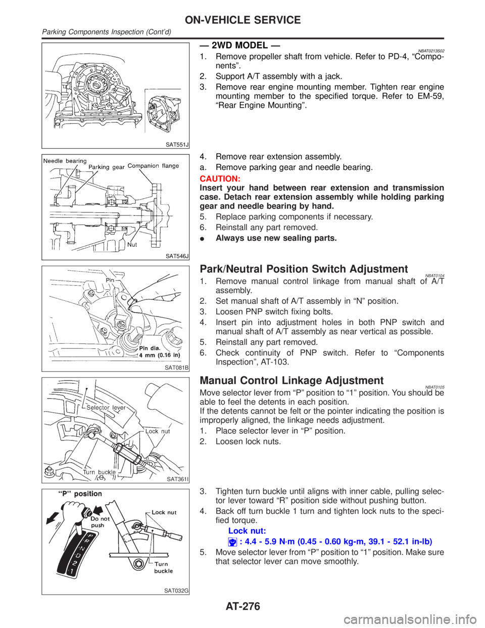
SAT546J
Rear Oil Seal and Companion Flange Oil Seal
Replacement
NBAT0212Ð 2WD MODEL ÐNBAT0212S01NOTE:
Replace rear extension assembly as a single unit because it can-
not be disassembled.
1. Remove propeller shaft. Refer to PD-4, ªComponentsº.
2. Remove exhaust mounting and mounting bracket.
3. Disconnect revolution and speedometer sensor harness con-
nector.
4. Support A/T assembly with a jack.
5. Remove rear engine mounting member. Tighten rear engine
mounting member to the specified torque. Refer to EM-59,
ªRear Engine Mountingº.
6. Remove rear extension assembly.
a. Remove parking gear and needle bearing.
CAUTION:
Insert your hand between rear extension and transmission
case. Detach rear extension assembly while holding parking
gear and needle bearing by hand.
7. Reinstall any part removed.
IAlways use new sealing parts.
SAT083J
Parking Components InspectionNBAT0213Ð 4WD MODEL ÐNBAT0213S011. Remove propeller shaft. Refer to PD-4, ªComponentsº.
2. Remove transfer case from vehicle. Refer to TF-119, ªRemovalº.
3. Remove A/T control cable bracket from transmission case.
SAT078B
4. Support A/T assembly with a jack.
5. Remove adapter case from transmission case.
6. Replace parking components if necessary.
7. Reinstall any part removed.
IAlways use new sealing parts.
GI
MA
EM
LC
EC
FE
TF
PD
AX
SU
BR
ST
RS
BT
HA
SC
EL
IDX
ON-VEHICLE SERVICE
Rear Oil Seal and Companion Flange Oil Seal Replacement
AT-275
Page 281 of 2395

SAT551J
Ð 2WD MODEL ÐNBAT0213S021. Remove propeller shaft from vehicle. Refer to PD-4, ªCompo-
nentsº.
2. Support A/T assembly with a jack.
3. Remove rear engine mounting member. Tighten rear engine
mounting member to the specified torque. Refer to EM-59,
ªRear Engine Mountingº.
SAT546J
4. Remove rear extension assembly.
a. Remove parking gear and needle bearing.
CAUTION:
Insert your hand between rear extension and transmission
case. Detach rear extension assembly while holding parking
gear and needle bearing by hand.
5. Replace parking components if necessary.
6. Reinstall any part removed.
IAlways use new sealing parts.
SAT081B
Park/Neutral Position Switch AdjustmentNBAT01041. Remove manual control linkage from manual shaft of A/T
assembly.
2. Set manual shaft of A/T assembly in ªNº position.
3. Loosen PNP switch fixing bolts.
4. Insert pin into adjustment holes in both PNP switch and
manual shaft of A/T assembly as near vertical as possible.
5. Reinstall any part removed.
6. Check continuity of PNP switch. Refer to ªComponents
Inspectionº, AT-103.
SAT361I
Manual Control Linkage AdjustmentNBAT0105Move selector lever from ªPº position to ª1º position. You should be
able to feel the detents in each position.
If the detents cannot be felt or the pointer indicating the position is
improperly aligned, the linkage needs adjustment.
1. Place selector lever in ªPº position.
2. Loosen lock nuts.
SAT032G
3. Tighten turn buckle until aligns with inner cable, pulling selec-
tor lever toward ªRº position side without pushing button.
4. Back off turn buckle 1 turn and tighten lock nuts to the speci-
fied torque.
Lock nut:
: 4.4 - 5.9 N´m (0.45 - 0.60 kg-m, 39.1 - 52.1 in-lb)
5. Move selector lever from ªPº position to ª1º position. Make sure
that selector lever can move smoothly.
ON-VEHICLE SERVICE
Parking Components Inspection (Cont'd)
AT-276
Page 284 of 2395

SAT017B
IWhen connecting torque converter to transmission, measure
distance ªAº to be certain that they are correctly assembled.
Distance ªAº:
25.0 mm (0.984 in) or more
SAT148K
IInstall converter to drive plate.
IAfter converter is installed to drive plate, rotate crankshaft
several turns and check to be sure that transmission
rotates freely without binding.
SAT149K
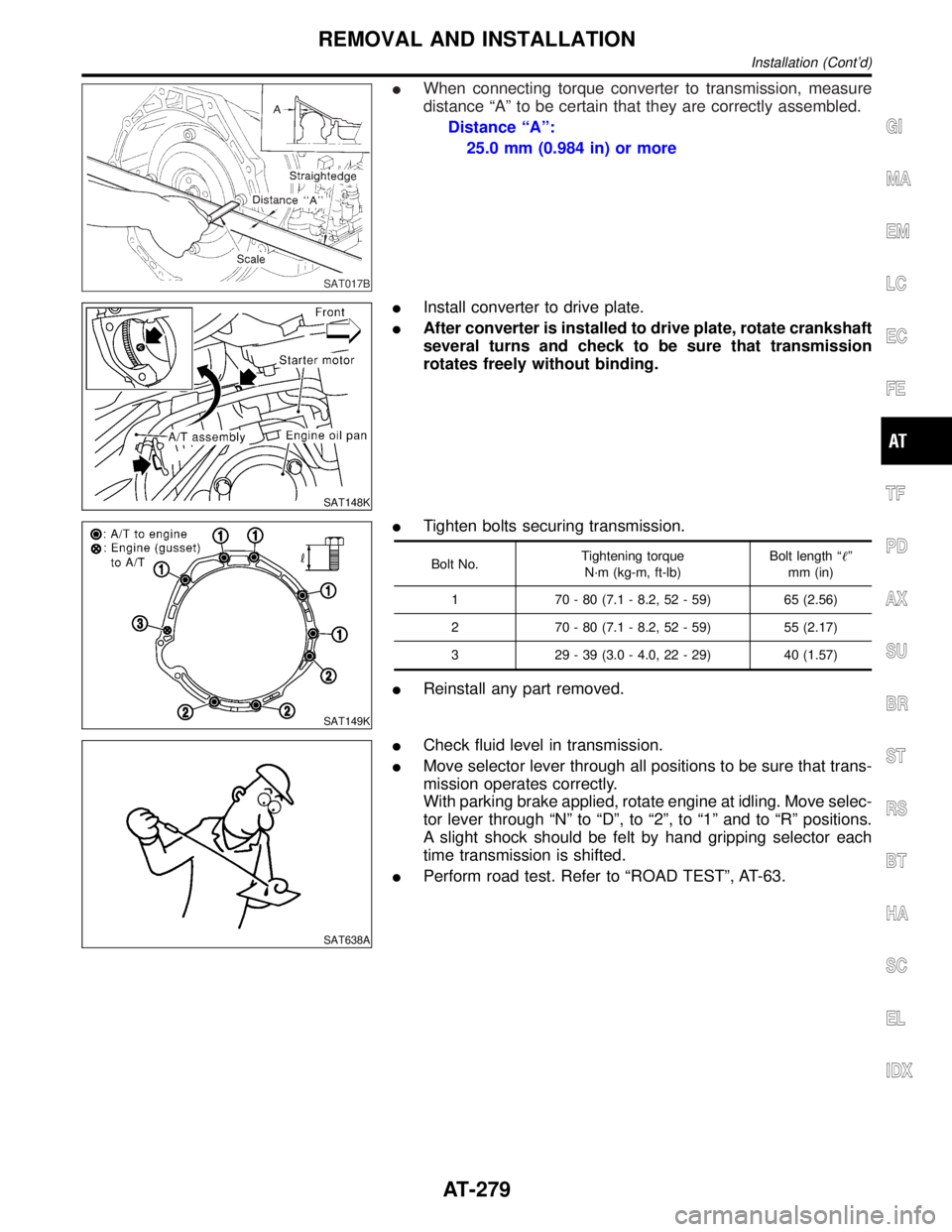
ITighten bolts securing transmission.
Bolt No.Tightening torque
N´m (kg-m, ft-lb)Bolt length ªº
mm (in)
1 70 - 80 (7.1 - 8.2, 52 - 59) 65 (2.56)
2 70 - 80 (7.1 - 8.2, 52 - 59) 55 (2.17)
3 29 - 39 (3.0 - 4.0, 22 - 29) 40 (1.57)
IReinstall any part removed.
SAT638A
ICheck fluid level in transmission.
IMove selector lever through all positions to be sure that trans-
mission operates correctly.
With parking brake applied, rotate engine at idling. Move selec-
tor lever through ªNº to ªDº, to ª2º, to ª1º and to ªRº positions.
A slight shock should be felt by hand gripping selector each
time transmission is shifted.
IPerform road test. Refer to ªROAD TESTº, AT-63.
GI
MA
EM
LC
EC
FE
TF
PD
AX
SU
BR
ST
RS
BT
HA
SC
EL
IDX
REMOVAL AND INSTALLATION
Installation (Cont'd)
AT-279
Page 291 of 2395
NBAT0111
SAT018B
1. Drain ATF through drain plug.
2. Remove turbine revolution sensor.
3. Remove torque converter by holding it firmly and turning while
pulling straight out.
SAT521G
4. Check torque converter one-way clutch.
a. Insert Tool into spline of one-way clutch inner race.
b. Hook bearing support unitized with one-way clutch outer race
with suitable wire.
c. Check that one-way clutch inner race rotates only clockwise
with Tool while holding bearing support with wire.
SAT021BB
5. Remove PNP switch from transmission case.
SAT754I
6. Remove oil pan.
IAlways place oil pan straight down so that foreign particles
inside will not move.
SAT522G
7. Place transmission into Tool with the control valve facing up.
DISASSEMBLY
AT-286
Page 293 of 2395
SAT353B
b. Remove bolts A and B, and remove control valve assembly
from transmission.
Bolt symbol Length mm (in)
A 33 (1.30)
B 45 (1.77)
SAT026B
c. Remove solenoid connector.
IBe careful not to damage connector.
SAT127B
d. Remove manual valve from control valve assembly.
SAT128B
12. Remove terminal cord assembly from transmission case while
pushing on stopper.
IBe careful not to damage cord.
IDo not remove terminal cord assembly unless it is dam-
aged.
DISASSEMBLY
AT-288