Page 2036 of 2395

Service Data and Specifications (SDS)
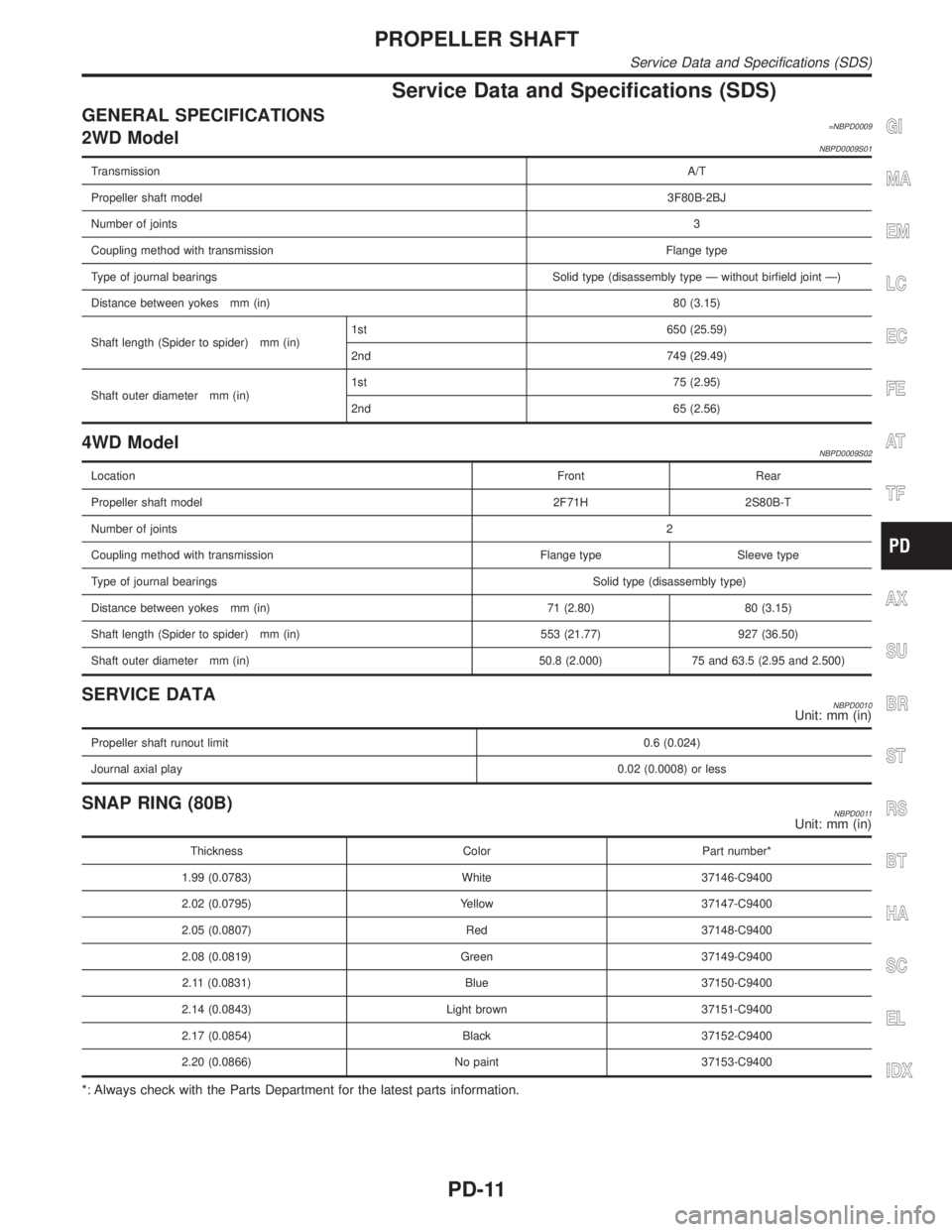
GENERAL SPECIFICATIONS=NBPD00092WD ModelNBPD0009S01
TransmissionA/T
Propeller shaft model3F80B-2BJ
Number of joints3
Coupling method with transmissionFlange type
Type of journal bearings Solid type (disassembly type Ð without birfield joint Ð)
Distance between yokes mm (in)80 (3.15)
Shaft length (Spider to spider) mm (in)1st 650 (25.59)
2nd 749 (29.49)
Shaft outer diameter mm (in)1st 75 (2.95)
2nd 65 (2.56)
4WD ModelNBPD0009S02
LocationFront Rear
Propeller shaft model 2F71H 2S80B-T
Number of joints2
Coupling method with transmission Flange type Sleeve type
Type of journal bearingsSolid type (disassembly type)
Distance between yokes mm (in) 71 (2.80) 80 (3.15)
Shaft length (Spider to spider) mm (in) 553 (21.77) 927 (36.50)
Shaft outer diameter mm (in) 50.8 (2.000) 75 and 63.5 (2.95 and 2.500)
SERVICE DATANBPD0010Unit: mm (in)
Propeller shaft runout limit0.6 (0.024)
Journal axial play0.02 (0.0008) or less
SNAP RING (80B)NBPD0011Unit: mm (in)
Thickness Color Part number*
1.99 (0.0783) White 37146-C9400
2.02 (0.0795) Yellow 37147-C9400
2.05 (0.0807) Red 37148-C9400
2.08 (0.0819) Green 37149-C9400
2.11 (0.0831) Blue 37150-C9400
2.14 (0.0843) Light brown 37151-C9400
2.17 (0.0854) Black 37152-C9400
2.20 (0.0866) No paint 37153-C9400
*: Always check with the Parts Department for the latest parts information.
GI
MA
EM
LC
EC
FE
AT
TF
AX
SU
BR
ST
RS
BT
HA
SC
EL
IDX
PROPELLER SHAFT
Service Data and Specifications (SDS)
PD-11
Page 2251 of 2395

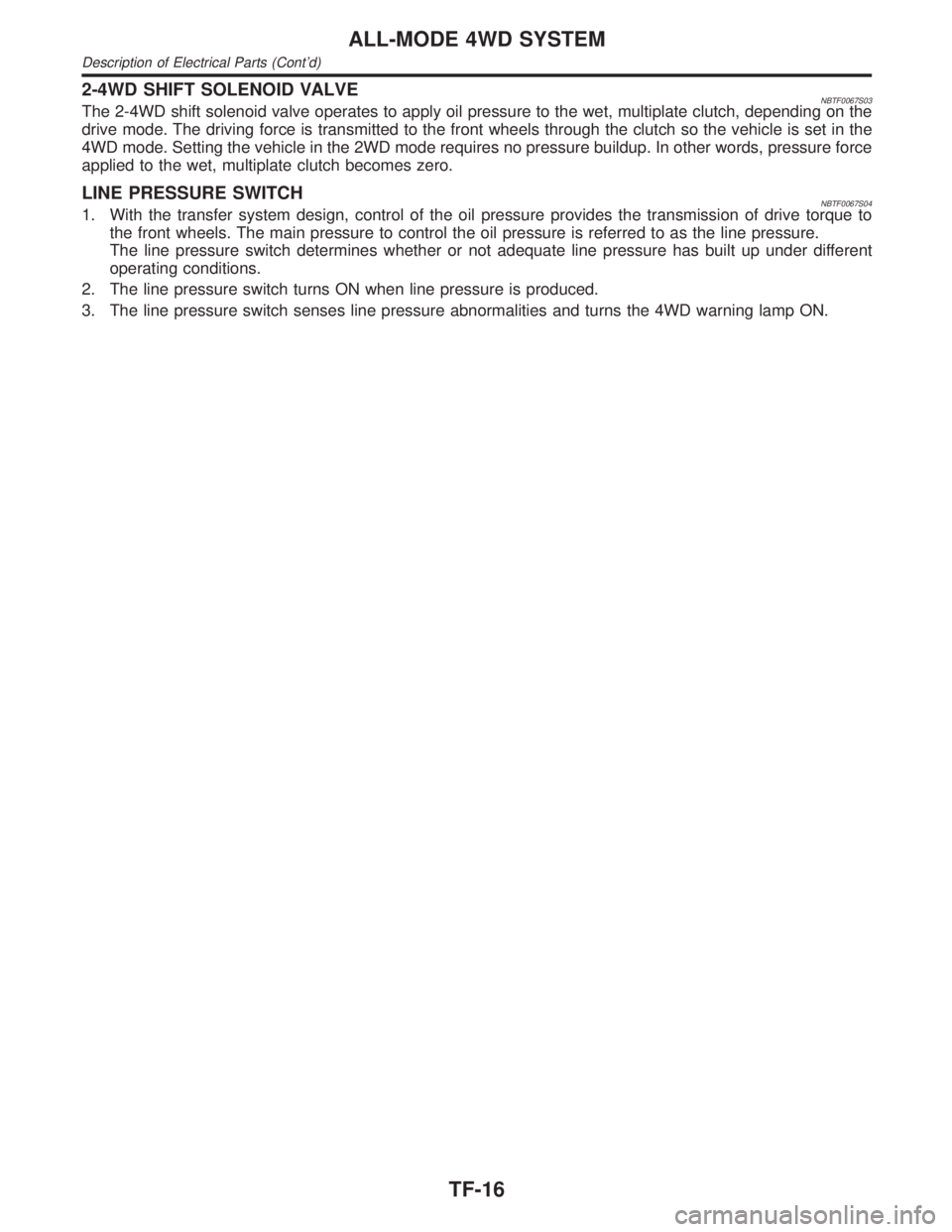
2-4WD SHIFT SOLENOID VALVENBTF0067S03The 2-4WD shift solenoid valve operates to apply oil pressure to the wet, multiplate clutch, depending on the
drive mode. The driving force is transmitted to the front wheels through the clutch so the vehicle is set in the
4WD mode. Setting the vehicle in the 2WD mode requires no pressure buildup. In other words, pressure force
applied to the wet, multiplate clutch becomes zero.
LINE PRESSURE SWITCHNBTF0067S041. With the transfer system design, control of the oil pressure provides the transmission of drive torque to
the front wheels. The main pressure to control the oil pressure is referred to as the line pressure.
The line pressure switch determines whether or not adequate line pressure has built up under different
operating conditions.
2. The line pressure switch turns ON when line pressure is produced.
3. The line pressure switch senses line pressure abnormalities and turns the 4WD warning lamp ON.
ALL-MODE 4WD SYSTEM
Description of Electrical Parts (Cont'd)
TF-16
Page 2354 of 2395

SMT897C
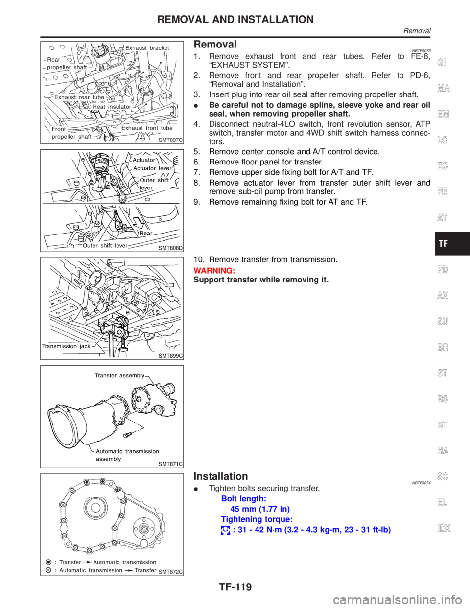
RemovalNBTF00731. Remove exhaust front and rear tubes. Refer to FE-8,
ªEXHAUST SYSTEMº.
2. Remove front and rear propeller shaft. Refer to PD-6,
ªRemoval and Installationº.
3. Insert plug into rear oil seal after removing propeller shaft.
IBe careful not to damage spline, sleeve yoke and rear oil
seal, when removing propeller shaft.
4. Disconnect neutral-4LO switch, front revolution sensor, ATP
switch, transfer motor and 4WD shift switch harness connec-
tors.
SMT808D
5. Remove center console and A/T control device.
6. Remove floor panel for transfer.
7. Remove upper side fixing bolt for A/T and TF.
8. Remove actuator lever from transfer outer shift lever and
remove sub-oil pump from transfer.
9. Remove remaining fixing bolt for AT and TF.
SMT899C
SMT871C
10. Remove transfer from transmission.
WARNING:
Support transfer while removing it.
SMT872C
InstallationNBTF0074ITighten bolts securing transfer.
Bolt length:
45 mm (1.77 in)
Tightening torque:
: 31 - 42 N´m (3.2 - 4.3 kg-m, 23 - 31 ft-lb)
GI
MA
EM
LC
EC
FE
AT
PD
AX
SU
BR
ST
RS
BT
HA
SC
EL
IDX
REMOVAL AND INSTALLATION
Removal
TF-119