2001 INFINITI QX4 transmission
[x] Cancel search: transmissionPage 1540 of 2395

greatly depending on the cellular network and cellular signal
strength. The system resets to ready when the system com-
pletes the dialing attempts. The vehicle owner can press the
button again if he or she still needs to contact the Communi-
cator Response Center.
IINFINITI Communicator automatically redials if communication
between the vehicle owner and Communicator Response Cen-
ter is lost for some reason.
IThe only way for a transmission to be officially terminated is for
the Communicator Response Center to send an end transmis-
sion signal, which turns off the indicator in the switch. (Com-
munication with Communicator Response Center can not be
terminated by the occupant.)
IIf the vehicle owner start the engine during a call, the conver-
sation may be interrupted. When this happens the system may
try to resume transmission once after the engine has been
started.
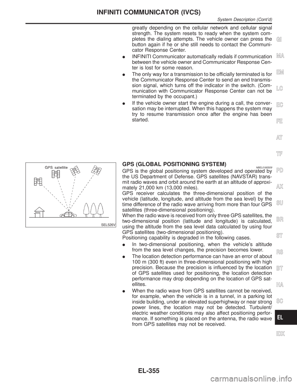
SEL526V
GPS (GLOBAL POSITIONING SYSTEM)NBEL0180S09GPS is the global positioning system developed and operated by
the US Department of Defense. GPS satellites (NAVSTAR) trans-
mit radio waves and orbit around the earth at an altitude of approxi-
mately 21,000 km (13,000 miles).
GPS receiver calculates the three-dimensional position of the
vehicle (latitude, longitude, and altitude from the sea level) by the
time difference of the radio wave arriving from more than four GPS
satellites (three-dimensional positioning).
When the radio wave is received from only three GPS satellites, the
two-dimensional position (latitude and longitude) is calculated,
using the altitude from the sea level data calculated by using four
GPS satellites (two-dimensional positioning).
Positioning capability is degraded in the following cases.
IIn two-dimensional positioning, when the vehicle's altitude
from the sea level changes, the precision becomes lower.
IThe location detection performance can have an error of about
100 m (300 ft) even in three-dimensional positioning with high
precision. Because the precision is influenced by the location
of GPS satellites used for positioning, the location detection
performance may drop depending on the location of GPS sat-
ellites.
IWhen the radio wave from GPS satellites cannot be received,
for example, when the vehicle is in a tunnel, in a parking lot
inside building, under an elevated superhighway or near strong
power lines, the location may not be detected. Turbulent/
electric weather conditions may also affect positioning perfor-
mance. If something is placed on the antenna, the radio wave
from GPS satellites may not be received.
GI
MA
EM
LC
EC
FE
AT
TF
PD
AX
SU
BR
ST
RS
BT
HA
SC
IDX
INFINITI COMMUNICATOR (IVCS)
System Description (Cont'd)
EL-355
Page 1541 of 2395

SEL100W
HANDSETNBEL0180S10NOTE:
IIf an optional handset is installed, INFINITI Communicator can
be used as a normal cellular phone.
IIf INFINITI Communicator is activated when INFINITI Commu-
nicator system's cellular phone is in use, the current phone
transmission will be cut and INFINITI Communicator will dial
the Communicator Response Center. The cellular handset will
be disabled, and communication with the Communicator
Response Center operator will be carried out through the
hands-free microphone.
IAfter communication with Communicator Response Center is
finished, the handset last number memory will be erased.
IWhile INFINITI Communicator is activated, the handset
becomes inoperative and all communication with the operator
is accomplished via the hands-free phone. When an activation
is terminated, the handset will be unlocked.
SEL588VA
TEL SWITCHNBEL0180S11When any of the TEL switches is pressed, the TEL switch which is
combined with the multiplex transmitting unit sends operational
commands to the IVCS unit. TEL switch has following three func-
tions.
IVolume adjust
IPlacing re-dial call
IPlacing memorized call (The telephone numbers are stored in
the handset. A maximum of 6 memories are operative.)
VOLUME SwitchNBEL0180S1103Voice volume from the front RH speaker can be adjusted by using
the VOLUME switch.
SEND/END Switch Operation (Without Navigation
System)
NBEL0180S1101IWhen a call is received, press SEND/END switch to permit
conversation.
IAt the completion of the conversation, press the SEND/END
switch to terminate the call.
ITo re-dial the last phone number, press SEND/END switch.
MEMORY Switch Operation (Without Navigation
System)
NBEL0180S1102IA maximum of 6 telephone numbers which stored in the
memory of the handset can be dialed by MEMORY switch
operation.
IThe last phone number is erased if the ignition switch is turned
off or if the INFINITI Communicator system has been activated.
IFor the procedure to input telephone numbers, refer to the
handset operation manual.
ITo select memory 1 to 6, push MEMORY switch A or B. Every
push on the switch changes the memory as follows.
SWITCH A: Memory 1,2,3,OFF
SWITCH B: Memory 4,5,6,OFF
INFINITI COMMUNICATOR (IVCS)
System Description (Cont'd)
EL-356
Page 1587 of 2395

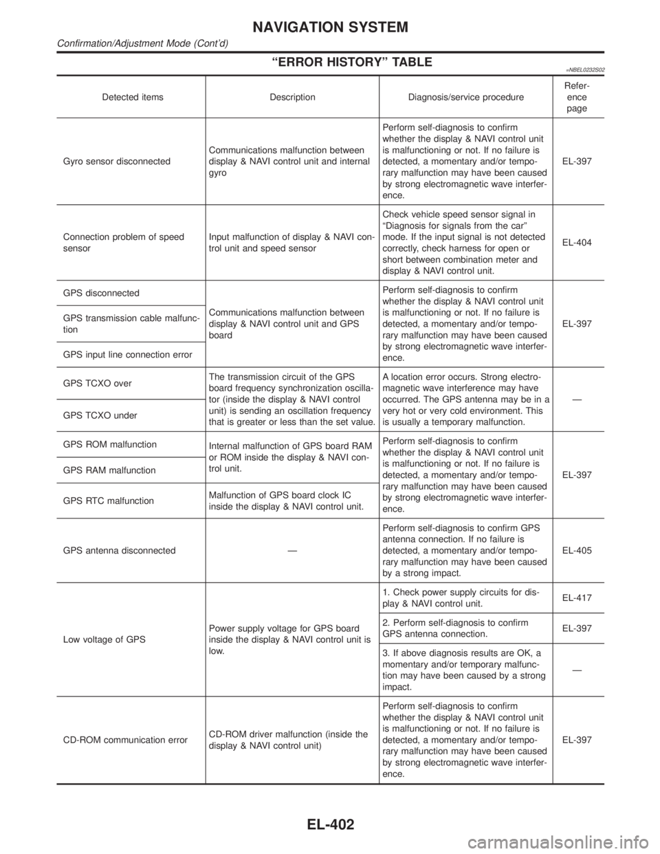
ªERROR HISTORYº TABLE=NBEL0232S02
Detected items Description Diagnosis/service procedureRefer-
ence
page
Gyro sensor disconnectedCommunications malfunction between
display & NAVI control unit and internal
gyroPerform self-diagnosis to confirm
whether the display & NAVI control unit
is malfunctioning or not. If no failure is
detected, a momentary and/or tempo-
rary malfunction may have been caused
by strong electromagnetic wave interfer-
ence.EL-397
Connection problem of speed
sensorInput malfunction of display & NAVI con-
trol unit and speed sensorCheck vehicle speed sensor signal in
ªDiagnosis for signals from the carº
mode. If the input signal is not detected
correctly, check harness for open or
short between combination meter and
display & NAVI control unit.EL-404
GPS disconnected
Communications malfunction between
display & NAVI control unit and GPS
boardPerform self-diagnosis to confirm
whether the display & NAVI control unit
is malfunctioning or not. If no failure is
detected, a momentary and/or tempo-
rary malfunction may have been caused
by strong electromagnetic wave interfer-
ence.EL-397 GPS transmission cable malfunc-
tion
GPS input line connection error
GPS TCXO overThe transmission circuit of the GPS
board frequency synchronization oscilla-
tor (inside the display & NAVI control
unit) is sending an oscillation frequency
that is greater or less than the set value.A location error occurs. Strong electro-
magnetic wave interference may have
occurred. The GPS antenna may be in a
very hot or very cold environment. This
is usually a temporary malfunction.Ð
GPS TCXO under
GPS ROM malfunction
Internal malfunction of GPS board RAM
or ROM inside the display & NAVI con-
trol unit.Perform self-diagnosis to confirm
whether the display & NAVI control unit
is malfunctioning or not. If no failure is
detected, a momentary and/or tempo-
rary malfunction may have been caused
by strong electromagnetic wave interfer-
ence.EL-397 GPS RAM malfunction
GPS RTC malfunctionMalfunction of GPS board clock IC
inside the display & NAVI control unit.
GPS antenna disconnected ÐPerform self-diagnosis to confirm GPS
antenna connection. If no failure is
detected, a momentary and/or tempo-
rary malfunction may have been caused
by a strong impact.EL-405
Low voltage of GPSPower supply voltage for GPS board
inside the display & NAVI control unit is
low.1. Check power supply circuits for dis-
play & NAVI control unit.EL-417
2. Perform self-diagnosis to confirm
GPS antenna connection.EL-397
3. If above diagnosis results are OK, a
momentary and/or temporary malfunc-
tion may have been caused by a strong
impact.Ð
CD-ROM communication errorCD-ROM driver malfunction (inside the
display & NAVI control unit)Perform self-diagnosis to confirm
whether the display & NAVI control unit
is malfunctioning or not. If no failure is
detected, a momentary and/or tempo-
rary malfunction may have been caused
by strong electromagnetic wave interfer-
ence.EL-397
NAVIGATION SYSTEM
Confirmation/Adjustment Mode (Cont'd)
EL-402
Page 1636 of 2395

Engine and Transmission HarnessNBEL0139
MEL082M
GI
MA
EM
LC
EC
FE
AT
TF
PD
AX
SU
BR
ST
RS
BT
HA
SC
IDX
HARNESS LAYOUT
Engine and Transmission Harness
EL-451
Page 1659 of 2395

9. Remove the crankshaft position sensors (REF and POS).
10. Remove drive belts and idler pulley with bracket.
11. Remove power steering oil pump, then put it aside holding with
a suitable wire.
12. Remove alternator.
SEM605G
13. Install engine slingers.
14. Remove front propeller shaft. (4WD)
Refer to PD-6, ªRemoval and Installationº.
15. Remove exhaust front tube heat insulators, then remove rear
heat oxygen sensors.
16. Remove exhaust front tube from both sides.
Refer to FE-8, ªRemoval and Installationº.
17. Remove front final drive. (4WD)
Refer to PD-18, ªRemoval and Installationº.
18. Remove starter motor.
19. Disconnect oil pressure switch harness connector.
SEM528G
20. Loosen and disconnect the bolts fixing the steering column
assembly lower joint and the power steering gear.
SEM471G
21. Set a suitable transmission jack under the front suspension
member and hoist engine with engine slingers.
EMQ0357D
22. Remove front engine mounting nuts from both sides.
OIL PAN
Removal (Cont'd)
EM-16
Page 1660 of 2395

SEM529G
SEM530G
23. Remove front suspension member bolts.
24. Lower the transmission jack carefully to secure clearance
between the oil pan and suspension member.
25. Remove A/T oil cooler tube.
26. Remove water hose and tube.
SEM469G
27. Remove the four engine-to-transmission bolts.
SEM463G
28. Remove aluminum oil pan bolts in numerical order.
SEM365E
29. Remove aluminum oil pan.
a. Insert tool between aluminum oil pan and cylinder block.
IBe careful not to damage aluminum mating surface.
IDo not insert screwdriver, or oil pan flange will be
deformed.
b. Slide tool by tapping its side with a hammer.
GI
MA
LC
EC
FE
AT
TF
PD
AX
SU
BR
ST
RS
BT
HA
SC
EL
IDX
OIL PAN
Removal (Cont'd)
EM-17
Page 1662 of 2395

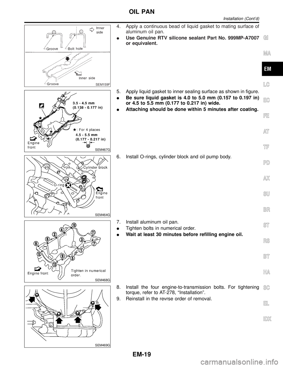
SEM159F
4. Apply a continuous bead of liquid gasket to mating surface of
aluminum oil pan.
IUse Genuine RTV silicone sealant Part No. 999MP-A7007
or equivalent.
SEM467G
5. Apply liquid gasket to inner sealing surface as shown in figure.
IBe sure liquid gasket is 4.0 to 5.0 mm (0.157 to 0.197 in)
or 4.5 to 5.5 mm (0.177 to 0.217 in) wide.
IAttaching should be done within 5 minutes after coating.
SEM464G
6. Install O-rings, cylinder block and oil pump body.
SEM468G
7. Install aluminum oil pan.
ITighten bolts in numerical order.
IWait at least 30 minutes before refilling engine oil.
SEM469G
8. Install the four engine-to-transmission bolts. For tightening
torque, refer to AT-278, ªInstallationº.
9. Reinstall in the revrse order of removal.
GI
MA
LC
EC
FE
AT
TF
PD
AX
SU
BR
ST
RS
BT
HA
SC
EL
IDX
OIL PAN
Installation (Cont'd)
EM-19
Page 1676 of 2395

SEM439G
SEM440G
17. Install RH and LH rocker covers.
Rocker cover tightening procedure:
ITighten in numerical order as shown in the figure.
a. Tighten bolts 1 to 10 in that order to 6.9 to 8.8 N´m (0.7 to 0.9
kg-m, 61 to 78 in-lb).
b. Then tighten bolts 1 to 10 as indicated in figure to 6.9 to 8.8
N´m (0.7 to 0.9 kg-m, 61 to 78 in-lb).
18. Hang engine using the right and left side engine slingers with
a suitable hoist.
19. Set a suitable transmission jack under the suspension mem-
ber.
20. Remove right and left side engine mounting nuts.
21. Remove right and left side suspension member bolts.
22. Install aluminum oil pan. Refer to EM-18, ªInstallationº.
23. Set ring gear stopper using the mounting bolt hole.
IBe careful not to damage the signal plate teeth.
SEM417G
24. Install crankshaft pulley to crankshaft.
IAlign pointer with TDC mark on crankshaft pulley.
SEM531G
25. Install crankshaft pulley bolt.
ILubricate thread and seat surface of the bolt with new
engine oil.
a. Tighten to 39 to 49 N´m (4.0 to 5.0 kg-m, 29 to 36 ft-lb).
b. Put a paint mark on the crankshaft pulley.
SEM963E
c. Again tighten by turning 60É to 66É, about the angle from one
hexagon bolt head corner to another.
26. Install camshaft position sensor (PHASE), crankshaft position
sensors (REF)/(POS) and CVTC sensors.
27. Reinstall removed parts in the reverse order of removal.
IWhen installing fuel tube and intake manifold collectors, refer
to EM-12, ªTIGHTENING PROCEDURESº.
IAfter starting engine, keep idling for three minutes. Then
rev engine up to 3,000 rpm under no load to purge air from
the high-pressure chamber of the chain tensioners. The
engine may produce a rattling noise. This indicates that
GI
MA
LC
EC
FE
AT
TF
PD
AX
SU
BR
ST
RS
BT
HA
SC
EL
IDX
TIMING CHAIN
Installation (Cont'd)
EM-33