Page 703 of 2395
4 DETECT MALFUNCTIONING PART
Check the following.
IHarness connectors E1, M1
IHarness connectors M33, F22
IHarness for open between ECM and intake air temperature sensor
IHarness for open between TCM (Transmission Control Module) and intake air temperature sensor
©Repair open circuit or short to power in harness or connectors.
5 CHECK INTAKE AIR TEMPERATURE SENSOR
Check resistance between intake air temperature sensor terminals 1 and 2 as shown in the figure.
SEF302X
OK or NG
OK©GO TO 6.
NG©Replace intake air temperature sensor.
6 CHECK INTERMITTENT INCIDENT
Refer to ªTROUBLE DIAGNOSIS FOR INTERMITTENT INCIDENTº, EC-140.
©INSPECTION END
DTC P0110 INTAKE AIR TEMPERATURE SENSOR
Diagnostic Procedure (Cont'd)
EC-168
Page 708 of 2395
4 DETECT MALFUNCTIONING PART
Check the following.
IHarness connectors F112, F28
IHarness for open between ECM and engine coolant temperature sensor
IHarness for open between TCM (Transmission Control Module) and engine coolant temperature sensor
©Repair open circuit or short to power in harness or connectors.
5 CHECK ENGINE COOLANT TEMPERATURE SENSOR
Check resistance between engine coolant temperature sensor terminals 1 and 2 as shown in the figure.
SEF304X
OK or NG
OK©GO TO 6.
NG©Replace engine coolant temperature sensor.
6 CHECK INTERMITTENT INCIDENT
Refer to ªTROUBLE DIAGNOSIS FOR INTERMITTENT INCIDENTº, EC-140.
©INSPECTION END
GI
MA
EM
LC
FE
AT
TF
PD
AX
SU
BR
ST
RS
BT
HA
SC
EL
IDX
DTC P0115 ENGINE COOLANT TEMPERATURE SENSOR (ECTS) (CIRCUIT)
Diagnostic Procedure (Cont'd)
EC-173
Page 717 of 2395

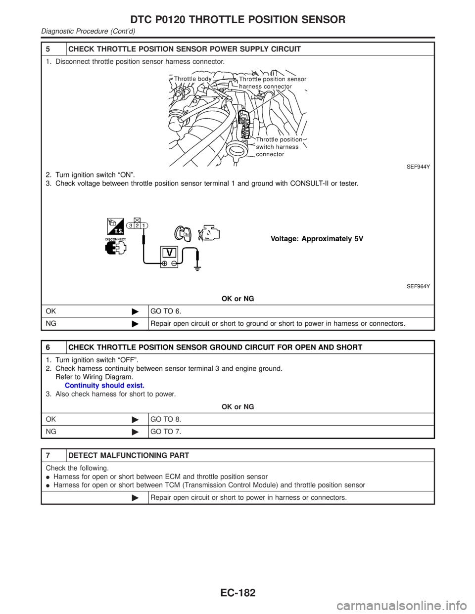
5 CHECK THROTTLE POSITION SENSOR POWER SUPPLY CIRCUIT
1. Disconnect throttle position sensor harness connector.
SEF944Y
2. Turn ignition switch ªONº.
3. Check voltage between throttle position sensor terminal 1 and ground with CONSULT-II or tester.
SEF964Y
OK or NG
OK©GO TO 6.
NG©Repair open circuit or short to ground or short to power in harness or connectors.
6 CHECK THROTTLE POSITION SENSOR GROUND CIRCUIT FOR OPEN AND SHORT
1. Turn ignition switch ªOFFº.
2. Check harness continuity between sensor terminal 3 and engine ground.
Refer to Wiring Diagram.
Continuity should exist.
3. Also check harness for short to power.
OK or NG
OK©GO TO 8.
NG©GO TO 7.
7 DETECT MALFUNCTIONING PART
Check the following.
IHarness for open or short between ECM and throttle position sensor
IHarness for open or short between TCM (Transmission Control Module) and throttle position sensor
©Repair open circuit or short to power in harness or connectors.
DTC P0120 THROTTLE POSITION SENSOR
Diagnostic Procedure (Cont'd)
EC-182
Page 726 of 2395

4 DETECT MALFUNCTIONING PART
Check the following.
IHarness connectors F112, F28
IHarness for open between ECM and engine coolant temperature sensor
IHarness for open between TCM (Transmission Control Module) and engine coolant temperature sensor
©Repair open circuit or short to power in harness or connectors.
5 CHECK ENGINE COOLANT TEMPERATURE SENSOR
Check resistance between engine coolant temperature sensor terminals 1 and 2 as shown in the figure.
SEF304X
OK or NG
OK©GO TO 6.
NG©Replace engine coolant temperature sensor.
6 CHECK THERMOSTAT OPERATION
When the engine is cold [lower than 70ÉC (158ÉF)] condition, grasp lower radiator hose and confirm the engine coolant
does not flow.
OK or NG
OK©GO TO 7.
NG©Repair or replace thermostat. Refer to LC-16, ªThermostatº.
7 CHECK INTERMITTENT INCIDENT
Refer to ªTROUBLE DIAGNOSIS FOR INTERMITTENT INCIDENTº, EC-140.
©INSPECTION END
GI
MA
EM
LC
FE
AT
TF
PD
AX
SU
BR
ST
RS
BT
HA
SC
EL
IDX
DTC P0125 ENGINE COOLANT TEMPERATURE SENSOR (ECTS)
Diagnostic Procedure (Cont'd)
EC-191
Page 921 of 2395

4 CHECK EVAP CONTROL SYSTEM PRESSURE SENSOR POWER SUPPLY CIRCUIT
1. Turn ignition switch ªONº.
2. Check voltage between EVAP control system pressure sensor terminal 3 and ground with CONSULT-II or tester.
SEF992Y
OK or NG
OK©GO TO 6.
NG©GO TO 5.
5 DETECT MALFUNCTIONING PART
Check the following.
IHarness connectors B101, B43
IHarness connectors B1, M2 and M94, F27
IHarness for open or short between EVAP control system pressure sensor and ECM
©Repair harness or connectors.
6 CHECK EVAP CONTROL SYSTEM PRESSURE SENSOR GROUND CIRCUIT FOR OPEN AND SHORT
1. Turn ignition switch ªOFFº.
2. Check harness continuity between EVAP control system pressure sensor terminal 1 and engine ground.
Refer to Wiring Diagram.
Continuity should exist.
3. Also check harness for short to power.
OK or NG
OK©GO TO 8.
NG©GO TO 7.
7 DETECT MALFUNCTIONING PART
Check the following.
IHarness connectors B101, B43
IHarness connectors B1, M2 and M94, F27
IHarness for open between EVAP control system pressure sensor and ECM
IHarness for open between EVAP control system pressure sensor and TCM (Transmission Control Module)
©Repair open circuit or short to power in harness or connectors.
DTC P0450 EVAPORATIVE EMISSION (EVAP) CONTROL SYSTEM PRESSURE
SENSOR
Diagnostic Procedure (Cont'd)
EC-386
Page 965 of 2395

10 CHECK IACV-AAC VALVE-II
1. Reconnect IACV-AAC valve harness connector and ECM harness connector.
2. Turn ignition switch ªONº and ªOFFº, and ensure the IACV-AAC valve makes operating sound according to the ignition
switch position.
SEF997Y
OK or NG
OK©GO TO 12.
NG©GO TO 11.
11 REPLACE IACV-AAC VALVE
1. Replace IACV-AAC valve assembly.
2. Perform ªIdle Air Volume Learningº, EC-57.
Is the result CMPLT or INCMP?
CMPLT or INCMP
CMPLT©INSPECTION END
INCMP©Follow the construction of ªIdle Air Volume Learningº.
12 CHECK TARGET IDLE SPEED
1. Turn ignition switch ªOFFº.
2. Reconnect all harness connectors and vacuum hoses.
3. Start engine and warm it up to normal operating temperature.
4. Also warm up transmission to normal operating temperature.
IFor A/T models with CONSULT-II, drive vehicle until ªFLUID TEMP SEº in ªDATA MONITORº mode of ªA/Tº system indi-
cates less than 0.9V.
IFor A/T models without CONSULT-II, drive vehicle for 10 minutes.
5. Stop vehicle with engine running.
6. Check target idle speed.
A/T: 750±50 rpm (in ªPº or ªNº position)
OK or NG
OK©GO TO 13.
NG©Perform ªIdle Air Volume Learningº, EC-57.
13 CHECK INTERMITTENT INCIDENT
Refer to ªTROUBLE DIAGNOSIS FOR INTERMITTENT INCIDENTº, EC-140.
©INSPECTION END
DTC P0505 IDLE AIR CONTROL VALVE (IACV) Ð AUXILIARY AIR CONTROL
(AAC) VALVE
Diagnostic Procedure (Cont'd)
EC-430
Page 975 of 2395

System DescriptionNBEC0264This circuit line (LAN) is used to control the smooth shifting up and down of A/T during the hard acceleration/
deceleration.
Pulse signals are exchanged between ECM and TCM (Transmission Control Module).
Be sure to erase the malfunction information such as DTC not only in TCM but also ECM after the A/T
related repair.
ECM Terminals and Reference ValueNBEC0672Specification data are reference values and are measured between each terminal and ground.
CAUTION:
Do not use ECM ground terminals when measuring input/output voltage. Doing so may result in dam-
age to the ECM's transistor. Use a ground other than ECM terminals, such as the ground.
TERMI-
NAL
NO.WIRE
COLORITEM CONDITION DATA (DC Voltage)
114 G/RCommunication line
(LAN)[Engine is running]
IIdle speedApproximately 2V
On Board Diagnosis LogicNBEC0266Malfunction is detected when ECM receives incorrect voltage from
TCM (Transmission Control Module) continuously.
Possible CauseNBEC0517IHarness or connectors
[The communication line circuit between ECM and TCM
(Transmission Control Module) is open or shorted.]
ITCM
IDead (Weak) battery
SEF058Y
DTC Confirmation ProcedureNBEC0267NOTE:
If ªDTC Confirmation Procedureº has been previously conducted,
always turn ignition switch ªOFFº and wait at least 10 seconds
before conducting the next test.
TESTING CONDITION:
Before performing the following procedure, confirm that bat-
tery voltage is more than 10.5V at idle.
WITH CONSULT-IINBEC0267S011) Turn ignition switch ªONº.
DTC P0600 A/T COMMUNICATION LINE
System Description
EC-440
Page 978 of 2395

Diagnostic ProcedureNBEC0270
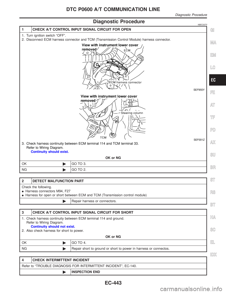
1 CHECK A/T CONTROL INPUT SIGNAL CIRCUIT FOR OPEN
1. Turn ignition switch ªOFFº.
2. Disconnect ECM harness connector and TCM (Transmission Control Module) harness connector.
SEF955Y
SEF001Z
3. Check harness continuity between ECM terminal 114 and TCM terminal 33.
Refer to Wiring Diagram.
Continuity should exist.
OK or NG
OK©GO TO 3.
NG©GO TO 2.
2 DETECT MALFUNCTION PART
Check the following.
IHarness connectors M94, F27
IHarness for open or short between ECM and TCM (Transmission control module)
©Repair harness or connectors.
3 CHECK A/T CONTROL INPUT SIGNAL CIRCUIT FOR SHORT
1. Check harness continuity between ECM terminal 114 and ground.
Refer to Wiring Diagram.
Continuity should not exist.
2. Also check harness for short to power.
OK or NG
OK©GO TO 4.
NG©Repair short to ground or short to power in harness or connectos.
4 CHECK INTERMITTENT INCIDENT
Refer to ªTROUBLE DIAGNOSIS FOR INTERMITTENT INCIDENTº, EC-140.
©INSPECTION END
GI
MA
EM
LC
FE
AT
TF
PD
AX
SU
BR
ST
RS
BT
HA
SC
EL
IDX
DTC P0600 A/T COMMUNICATION LINE
Diagnostic Procedure
EC-443