2001 INFINITI QX4 transmission
[x] Cancel search: transmissionPage 1138 of 2395
Component DescriptionNBEC0361The malfunction information related to A/T (Automatic Transmission) is transferred through the line (circuit)
from TCM (Transmission control module) to ECM. Therefore, be sure to erase the malfunction information such
as DTC not only in TCM (Transmission control module) but also ECM after the A/T related repair.
On Board Diagnosis LogicNBEC0363Malfunction is detected when an incorrect signal from TCM (Trans-
mission control module) is sent to ECM.
Possible CauseNBEC0594IHarness or connectors
[The communication line circuit between ECM and TCM
(Transmission control module) is open or shorted.]
IDead (Weak) battery
ITCM (Transmission control module)
SEF058Y
DTC Confirmation ProcedureNBEC0364NOTE:
If ªDTC Confirmation Procedureº has been previously conducted,
always turn ignition switch ªOFFº and wait at least 10 seconds
before conducting the next test.
TESTING CONDITION:
Before performing the following procedure, confirm that bat-
tery voltage is more than 10.5V at idle.
WITH CONSULT-IINBEC0364S011) Turn ignition switch ªONº.
2) Select ªDATA MONITORº mode with CONSULT-II.
3) Start engine and wait at least 40 seconds.
4) If 1st trip DTC is detected, go to ªDTC P0600 A/T COMMUNI-
CATION LINE Diagnostic Procedureº, EC-443.
WITH GSTNBEC0364S02Follow the procedure ªWITH CONSULT-IIº above.
GI
MA
EM
LC
FE
AT
TF
PD
AX
SU
BR
ST
RS
BT
HA
SC
EL
IDX
DTC P1605 A/T DIAGNOSIS COMMUNICATION LINE
Component Description
EC-603
Page 1139 of 2395
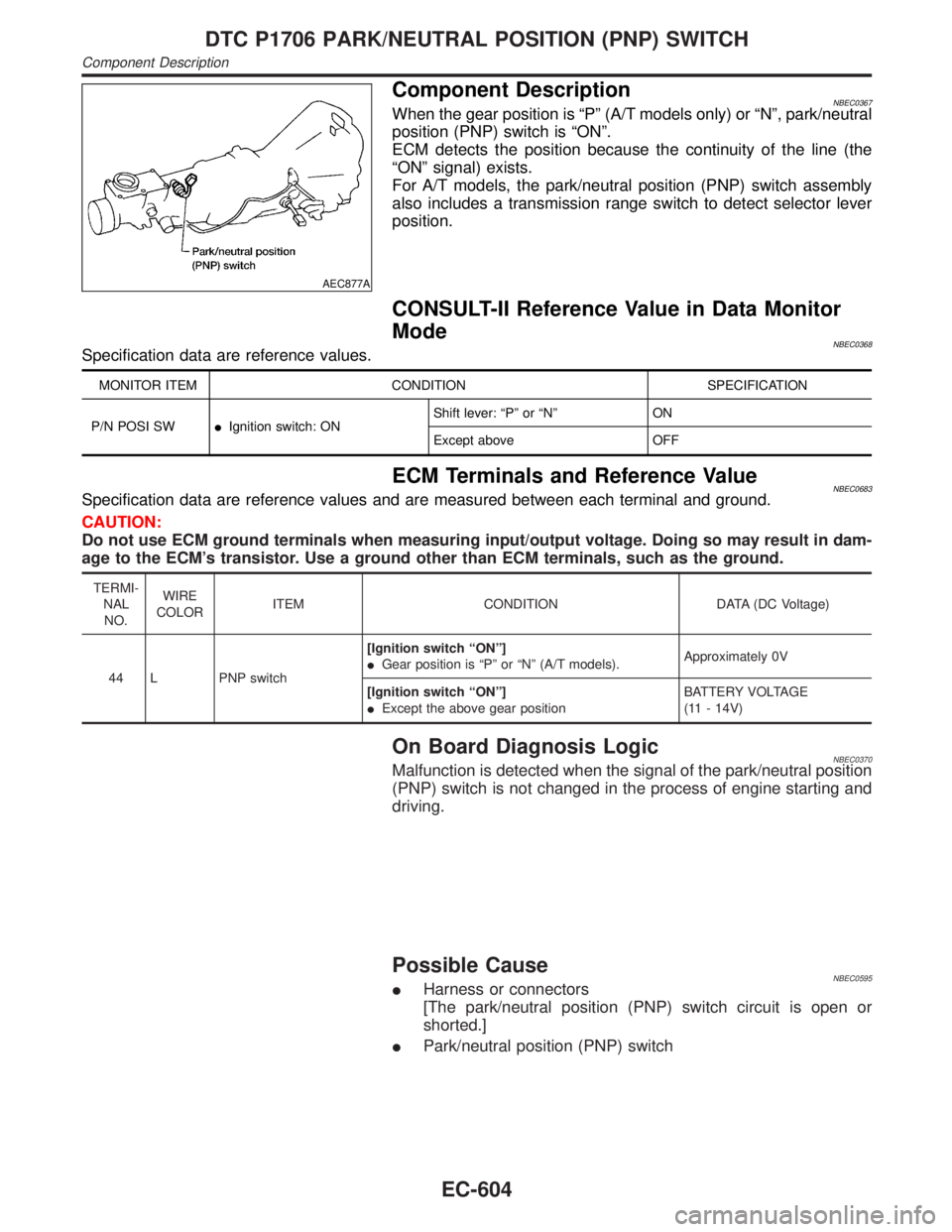
AEC877A
Component DescriptionNBEC0367When the gear position is ªPº (A/T models only) or ªNº, park/neutral
position (PNP) switch is ªONº.
ECM detects the position because the continuity of the line (the
ªONº signal) exists.
For A/T models, the park/neutral position (PNP) switch assembly
also includes a transmission range switch to detect selector lever
position.
CONSULT-II Reference Value in Data Monitor
Mode
NBEC0368Specification data are reference values.
MONITOR ITEM CONDITION SPECIFICATION
P/N POSI SWIIgnition switch: ONShift lever: ªPº or ªNº ON
Except above OFF
ECM Terminals and Reference ValueNBEC0683Specification data are reference values and are measured between each terminal and ground.
CAUTION:
Do not use ECM ground terminals when measuring input/output voltage. Doing so may result in dam-
age to the ECM's transistor. Use a ground other than ECM terminals, such as the ground.
TERMI-
NAL
NO.WIRE
COLORITEM CONDITION DATA (DC Voltage)
44 L PNP switch[Ignition switch ªONº]
IGear position is ªPº or ªNº (A/T models).Approximately 0V
[Ignition switch ªONº]
IExcept the above gear positionBATTERY VOLTAGE
(11 - 14V)
On Board Diagnosis LogicNBEC0370Malfunction is detected when the signal of the park/neutral position
(PNP) switch is not changed in the process of engine starting and
driving.
Possible CauseNBEC0595IHarness or connectors
[The park/neutral position (PNP) switch circuit is open or
shorted.]
IPark/neutral position (PNP) switch
DTC P1706 PARK/NEUTRAL POSITION (PNP) SWITCH
Component Description
EC-604
Page 1177 of 2395
3 DETECT MALFUNCTIONING PART
Check the following.
IHarness connectors E1, M1
IHarness for open or short between ECM and refrigerant pressure sensor
©Repair harness or connectors.
4 CHECK REFRIGERANT PRESSURE SENSOR GROUND CIRCUIT FOR OPEN AND SHORT
1. Turn ignition switch ªOFFº.
2. Check harness continuity between refrigerant pressure sensor terminal 1 and engine ground. Refer to Wiring Diagram.
Continuity should exist.
3. Also check harness for short to power.
OK or NG
OK©GO TO 6.
NG©GO TO 5.
5 DETECT MALFUNCTIONING PART
Check the following.
IHarness connectors E1, M1 and M33, F22
IHarness connectors F23, M32
IHarness for open between ECM and refrigerant pressure sensor
IHarness for open between TCM (Transmission control module) and refrigerant pressure sensor
©Repair open circuit or short to power in harness or connectors.
6 CHECK REFRIGERANT PRESSURE SENSOR INPUT SIGNAL CIRCUIT FOR OPEN AND SHORT
1. Disconnect ECM harness connector.
2. Check harness continuity between ECM terminal 81 and refrigerant pressure sensor terminal 2. Refer to Wiring Dia-
gram.
Continuity should exist.
3. Also check harness for short to ground and short to power.
OK or NG
OK©GO TO 8.
NG©GO TO 7.
7 DETECT MALFUNCTIONING PART
Check the following.
IHarness connectors E1, M1 and M94, F27
IHarness for open or short between ECM and refrigerant pressure sensor
©Repair open circuit or short to ground or short to power in harness or connectors.
8 CHECK REFRIGERANT PRESSURE SENSOR
Refer to HA-14, ªRefrigerant pressure sensorº.
OK or NG
OK©GO TO 9.
NG©Replace refrigerant pressure sensor.
9 CHECK INTERMITTENT INCIDENT
Refer to ªTROUBLE DIAGNOSIS FOR INTERMITTENT INCIDENTº, EC-140.
©INSPECTION END
REFRIGERANT PRESSURE SENSOR
Diagnostic Procedure (Cont'd)
EC-642
Page 1188 of 2395
Schematic ................................................................255
Wiring Diagram - D/LOCK -.....................................256
Trouble Diagnoses...................................................261
MULTI-REMOTE CONTROL SYSTEM.......................270
Component Parts and Harness Connector
Location ...................................................................270
System Description ..................................................270
Schematic ................................................................273
Wiring Diagram - MULTI - .......................................274
Trouble Diagnoses...................................................277
ID Code Entry Procedure ........................................289
Remote Controller Battery Replacement.................293
THEFT WARNING SYSTEM.......................................294
Component Parts and Harness Connector
Location ...................................................................294
System Description ..................................................295
Schematic ................................................................298
Wiring Diagram - THEFT -.......................................300
Trouble Diagnoses...................................................306
SMART ENTRANCE CONTROL UNIT.......................319
Description ...............................................................319
Schematic ................................................................322
Smart Entrance Control Unit Inspection Table ........324
INTEGRATED HOMELINK TRANSMITTER...............325
Wiring Diagram - TRNSMT - ...................................325
Trouble Diagnoses...................................................326
IVIS (INFINITI VEHICLE IMMOBILIZER SYSTEM -
NATS)...........................................................................328
Component Parts and Harness Connetor
Location ...................................................................328
System Description ..................................................329
System Composition ................................................329
Wiring Diagram - NATS -.........................................330
CONSULT-II .............................................................331
Trouble Diagnoses...................................................334
How to Replace IVIS (NATS) IMMU .......................347
INFINITI COMMUNICATOR (IVCS)............................348
Precaution ................................................................348
Communicator Response Center Telephone
Number for Technicians ...........................................348
Component Parts and Harness Connector
Location ...................................................................349System Description ..................................................350
Schematic ................................................................358
Wiring Diagram - IVCS -..........................................359
CONSULT-II .............................................................363
Trouble Diagnoses...................................................368
Trouble Diagnoses for Intermittent Incident ............377
Demonstration Mode ...............................................379
System Setting (When IVCS Unit is Replaced) ......381
NAVIGATION SYSTEM...............................................385
Component Parts Location ......................................385
System Description ..................................................386
Schematic ................................................................393
Wiring Diagram - NAVI - ..........................................394
Self-diagnosis Mode ................................................397
Confirmation/Adjustment Mode ...............................400
Setting Mode............................................................410
Trouble diagnoses ...................................................417
This Condition is Not Abnormal ...............................423
Program Loading .....................................................432
Initialization ..............................................................433
ELECTRICAL UNITS LOCATION...............................436
Engine Compartment ...............................................436
Passenger Compartment .........................................438
HARNESS LAYOUT....................................................440
How to Read Harness Layout .................................440
Outline......................................................................441
Main Harness...........................................................442
Engine Room Harness ............................................444
Engine Control Harness ..........................................446
Body Harness LH ....................................................448
Body Harness RH ....................................................449
Back Door Harness .................................................450
Engine and Transmission Harness..........................451
Room Lamp Harness...............................................452
Air Bag Harness ......................................................453
Front Door Harness .................................................454
Rear Door Harness..................................................455
BULB SPECIFICATIONS............................................456
Headlamp.................................................................456
Exterior Lamp ..........................................................456
Interior Lamp............................................................456
WIRING DIAGRAM CODES (CELL CODES).............457GI
MA
EM
LC
EC
FE
AT
TF
PD
AX
SU
BR
ST
RS
BT
HA
SC
IDX
CONTENTS(Cont'd)
EL-3
Page 1289 of 2395
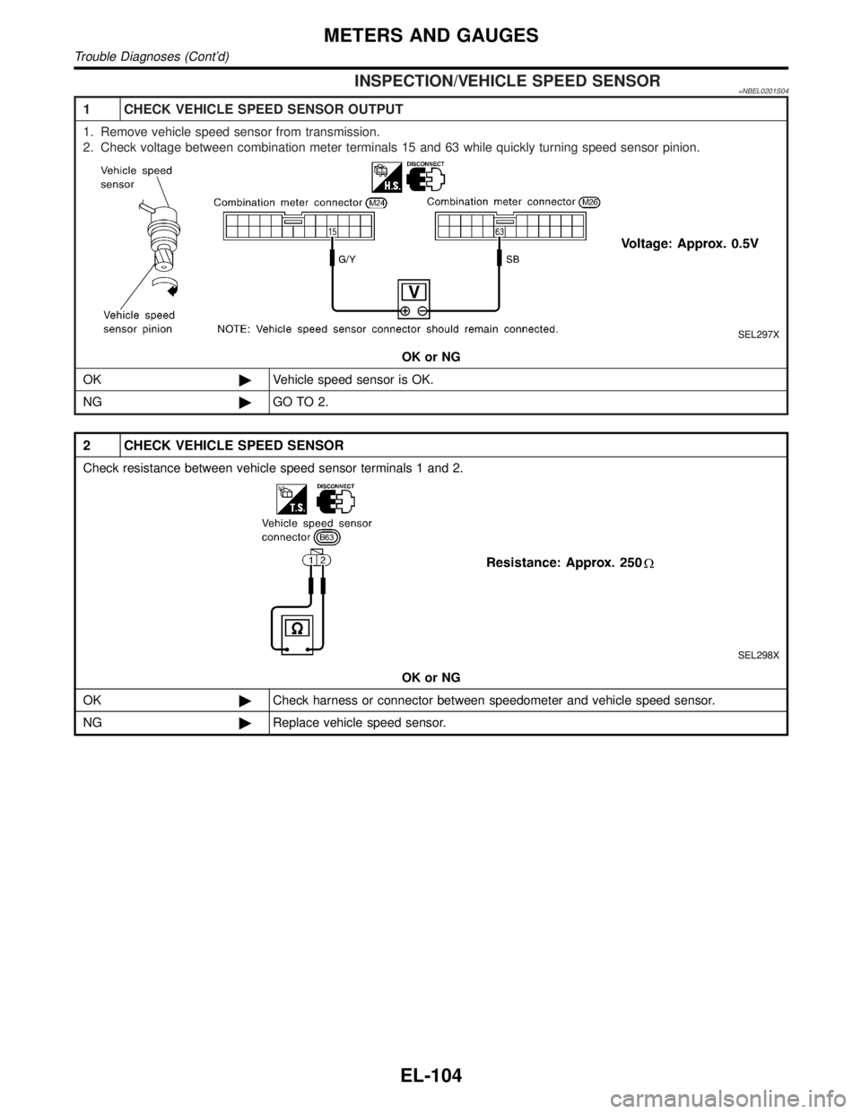
INSPECTION/VEHICLE SPEED SENSOR=NBEL0201S04
1 CHECK VEHICLE SPEED SENSOR OUTPUT
1. Remove vehicle speed sensor from transmission.
2. Check voltage between combination meter terminals 15 and 63 while quickly turning speed sensor pinion.
SEL297X
OK or NG
OK©Vehicle speed sensor is OK.
NG©GO TO 2.
2 CHECK VEHICLE SPEED SENSOR
Check resistance between vehicle speed sensor terminals 1 and 2.
SEL298X
OK or NG
OK©Check harness or connector between speedometer and vehicle speed sensor.
NG©Replace vehicle speed sensor.
METERS AND GAUGES
Trouble Diagnoses (Cont'd)
EL-104
Page 1294 of 2395
MEL005H
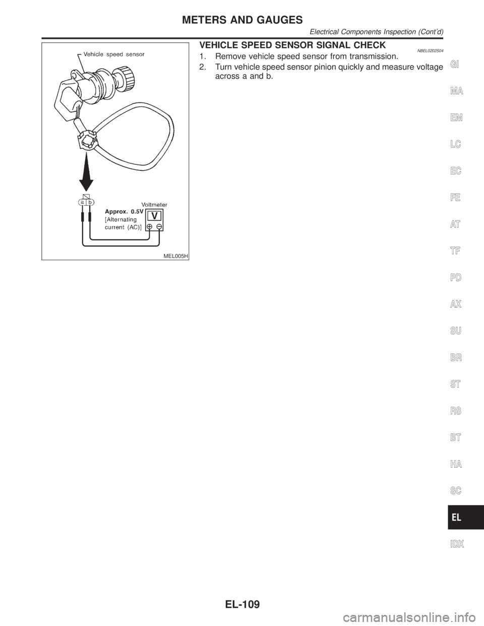
VEHICLE SPEED SENSOR SIGNAL CHECKNBEL0202S041. Remove vehicle speed sensor from transmission.
2. Turn vehicle speed sensor pinion quickly and measure voltage
across a and b.
GI
MA
EM
LC
EC
FE
AT
TF
PD
AX
SU
BR
ST
RS
BT
HA
SC
IDX
METERS AND GAUGES
Electrical Components Inspection (Cont'd)
EL-109
Page 1407 of 2395
System DescriptionNBEL0216Refer to Owner's Manual for ASCD operating instructions.
POWER SUPPLY AND GROUNDNBEL0216S01Power is supplied at all times:
Ithrough 10A fuse [No. 14, located in the fuse block (J/B)]
Ito the stop lamp switch terminal 1, and
Ithrough 7.5A fuse (No. 52, located in fuse and fusible link box)
Ito the horn relay terminals 1 and 3.
When ignition switch is in the ON or START position, power is supplied:
Ithrough 7.5A fuse [No. 11, located in the fuse block (J/B)]
Ito ASCD brake switch terminal 1 and
Ito ASCD control unit terminal 5,
Ithrough 10A fuse [No. 18, located in the fuse block (J/B)]
Ito park/neutral position relay terminal 1,
Ithrough 10A fuse [No. 8, located in the fuse block (J/B)]
Ito combination meter terminal 66, and
When park/neutral position switch is in the P or N position, ground is supplied:
Ito park/neutral position relay terminal 2
Ithrough park/neutral position switch and body grounds B55 and B75.
When ASCD main switch is depressed (ON), ground is supplied:
Ito ASCD control unit terminal 9
Ifrom ASCD steering switch terminal 4
Ito ASCD steering switch terminal 5
Ithrough body grounds M4, M66 and M147
then ASCD control unit holds CRUISE condition and illuminates CRUISE indicator.
Ground is supplied:
Ifrom ASCD control unit terminal 15
Ito combination meter terminal 46.
OPERATIONNBEL0216S02Set OperationNBEL0216S0201To activate the ASCD, all following conditions must exist.
IGround supply to ASCD control unit terminal 9 (Main switch is in ON position.)
IPower supply to ASCD control unit terminal 8 (Brake pedal is released and A/T selector lever is in other
than P and N position.)
IVehicle speed is between 40 km/h (25 MPH) and 144 km/h (89 MPH). (Signal from combination meter)
When the SET/COAST switch is depressed, power is supplied:
Ifrom ASCD steering switch terminal 2
Ito ASCD control unit terminal 11.
And then ASCD pump is activated to control throttle wire and ASCD control unit supply ground
Ito combination meter terminals 51 to illuminate SET indicator.
A/T Overdrive Control during Cruise Control DrivingNBEL0216S0202When the vehicle speed is approximately 3 km/h (2 MPH) below set speed, a signal is sent
Ifrom ASCD control unit terminal 10
Ito TCM (transmission control module) terminal 24.
When this occurs, the TCM (transmission control module) cancels overdrive.
After vehicle speed is approximately 1 km/h (1 MPH) below set speed, overdrive is reactivated.
ASCD Shifting ControlNBEL0216S0203During ASCD cruise, ASCD control unit controls A/T shifting to avoid uncomfortable shifting.
This is used to control the signals below.
IThrottle position sensor from ECM
AUTOMATIC SPEED CONTROL DEVICE (ASCD)
System Description
EL-222
Page 1536 of 2395
SYSTEM LIMITATIONSNBEL0180S03Service AreaNBEL0180S0301Depending on the cellular provider chosen, service is provided in
the 48 contiguous states. Service is not available in Alaska, Hawaii,
Canada, or Mexico. The Communicator Response Center will not
be able to locate the customer's vehicle outside of the continental
United States.
Inoperative if Cellular Phone is Inactive or InoperativeNBEL0180S0302INFINITI Communicator will be inoperative if the customer does not
have an active account with cellular provider, since INFINITI Com-
municator relies on the cellular network. When the INFINITI Com-
municator system is outside of cellular service, the ªNO SERVICEº
indicator will illuminate. If you try to activate INFINITI
Communicator, the REQUEST will be cancelled. Cellular phone
transmission may become temporarily disabled, or interrupted by
environmental factors like tunnels, bridges, or tall buildings. In such
cases, INFINITI Communicator will re-dial up to four times. After
several failed attempts, the system will quit dialing and return to
normal mode.
Inoperative if The System is in The Demonstraiton
Mode
NBEL0180S0303The INFINITI Communicator system remains in the demonstration
mode until the setup procedures are completed. If the system is
activated in this mode, the Communicator Response Center will
recognize this operation as a demonstration and will not provide
any service. The system can be changed to the demonstration
mode by using CONSULT-II to check the system operation. Do not
forget to turn off the demonstration mode after confirmation.
BatteryNBEL0180S0304Since INFINITI Communicator is powered by the vehicle's battery,
if the battery is removed, damaged or discharged, the system will
not work.
Inopertive if Cellular System is BusyNBEL0180S0305When INFINITI Communicator tries to contact the Communicator
Response Center, but the cellular network is busy, the system
attempts to re-dial for up to two hours. This time varies greatly
depending on the cellular network and cellular signal strength. The
system resets to ready when the system completes the re-dialing
attempts.
RoamingNBEL0180S0306If the customer's cellular provider does not have a roaming agree-
ment with the provider where the vehicle locates, it may not be
possible to use the lines of a different cellular provider. Therefore,
it is impossible that INFINITI Communicator will contact the Com-
municator Response Center.
Special Cellular FeaturesNBEL0180S0307Some cellular carriers offer custom phone numbers that are
assigned a Personal Identification Number (PIN). The cellular
phone user is required to enter the PIN anytime a phone call is
made. The INFINITI Communicator system is not compatible with
the PIN feature. A PIN requirement on the cellular phone will cause
the INFINITI Communicator system to be inoperative.
Other special features such as call waiting, voice mail, call
forwarding, etc. can interfere with INFINITI Communicator system
operation.
GI
MA
EM
LC
EC
FE
AT
TF
PD
AX
SU
BR
ST
RS
BT
HA
SC
IDX
INFINITI COMMUNICATOR (IVCS)
System Description (Cont'd)
EL-351