2001 INFINITI QX4 vin
[x] Cancel search: vinPage 1750 of 2395
SGI285
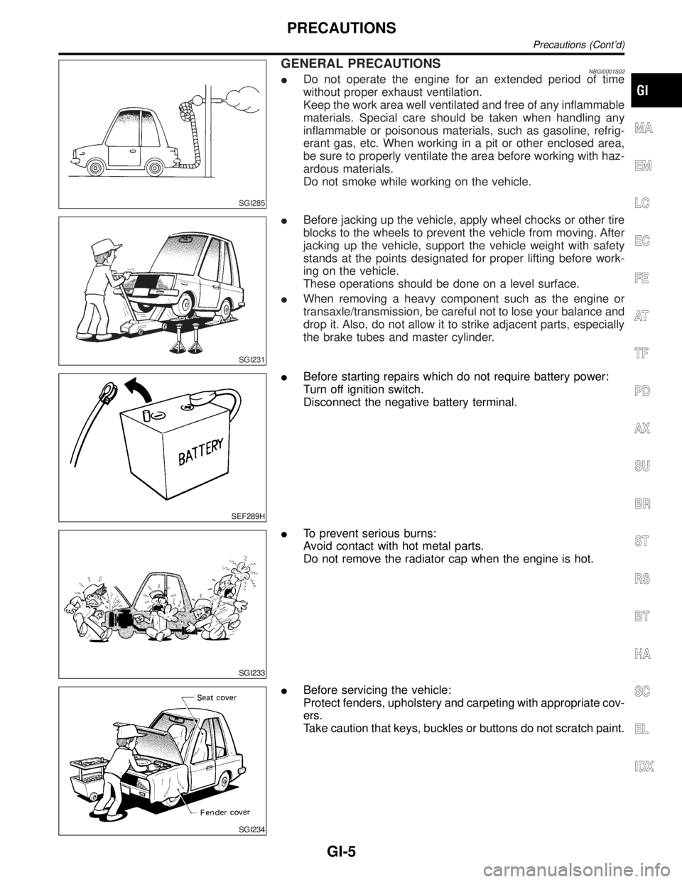
GENERAL PRECAUTIONSNBGI0001S02IDo not operate the engine for an extended period of time
without proper exhaust ventilation.
Keep the work area well ventilated and free of any inflammable
materials. Special care should be taken when handling any
inflammable or poisonous materials, such as gasoline, refrig-
erant gas, etc. When working in a pit or other enclosed area,
be sure to properly ventilate the area before working with haz-
ardous materials.
Do not smoke while working on the vehicle.
SGI231
IBefore jacking up the vehicle, apply wheel chocks or other tire
blocks to the wheels to prevent the vehicle from moving. After
jacking up the vehicle, support the vehicle weight with safety
stands at the points designated for proper lifting before work-
ing on the vehicle.
These operations should be done on a level surface.
IWhen removing a heavy component such as the engine or
transaxle/transmission, be careful not to lose your balance and
drop it. Also, do not allow it to strike adjacent parts, especially
the brake tubes and master cylinder.
SEF289H
IBefore starting repairs which do not require battery power:
Turn off ignition switch.
Disconnect the negative battery terminal.
SGI233
ITo prevent serious burns:
Avoid contact with hot metal parts.
Do not remove the radiator cap when the engine is hot.
SGI234
IBefore servicing the vehicle:
Protect fenders, upholstery and carpeting with appropriate cov-
ers.
Take caution that keys, buckles or buttons do not scratch paint.
MA
EM
LC
EC
FE
AT
TF
PD
AX
SU
BR
ST
RS
BT
HA
SC
EL
IDX
PRECAUTIONS
Precautions (Cont'd)
GI-5
Page 1768 of 2395
SEL272V
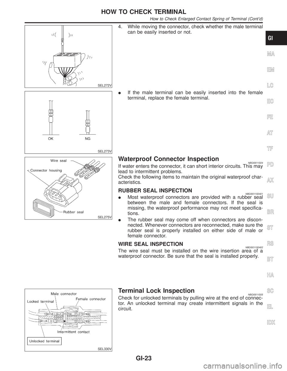
4. While moving the connector, check whether the male terminal
can be easily inserted or not.
SEL273V
IIf the male terminal can be easily inserted into the female
terminal, replace the female terminal.
SEL275V
Waterproof Connector InspectionNBGI0011S04If water enters the connector, it can short interior circuits. This may
lead to intermittent problems.
Check the following items to maintain the original waterproof char-
acteristics.
RUBBER SEAL INSPECTIONNBGI0011S0401IMost waterproof connectors are provided with a rubber seal
between the male and female connectors. If the seal is
missing, the waterproof performance may not meet specifica-
tions.
IThe rubber seal may come off when connectors are discon-
nected. Whenever connectors are reconnected, make sure the
rubber seal is properly installed on either side of male or
female connector.
WIRE SEAL INSPECTIONNBGI0011S0402The wire seal must be installed on the wire insertion area of a
waterproof connector. Be sure that the seal is installed properly.
SEL330V
Terminal Lock InspectionNBGI0011S05Check for unlocked terminals by pulling wire at the end of connec-
tor. An unlocked terminal may create intermittent signals in the
circuit.
MA
EM
LC
EC
FE
AT
TF
PD
AX
SU
BR
ST
RS
BT
HA
SC
EL
IDX
HOW TO CHECK TERMINAL
How to Check Enlarged Contact Spring of Terminal (Cont'd)
GI-23
Page 1770 of 2395
Incident Simulation TestsNBGI0004S02INTRODUCTIONNBGI0004S0201Sometimes the symptom is not present when the vehicle is brought
in for service. If possible, re-create the conditions present at the
time of the incident. Doing so may help avoid a No Trouble Found
Diagnosis. The following section illustrates ways to simulate the
conditions/environment under which the owner experiences an
electrical incident.
The section is broken into the six following topics:
IVehicle vibration
IHeat sensitive
IFreezing
IWater intrusion
IElectrical load
ICold or hot start up
Get a thorough description of the incident from the customer. It is
important for simulating the conditions of the problem.
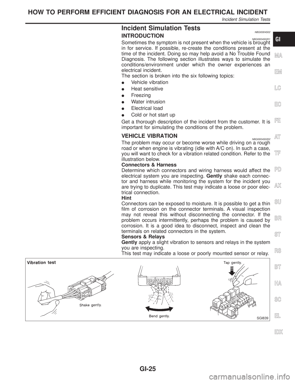
VEHICLE VIBRATIONNBGI0004S0202The problem may occur or become worse while driving on a rough
road or when engine is vibrating (idle with A/C on). In such a case,
you will want to check for a vibration related condition. Refer to the
illustration below.
Connectors & Harness
Determine which connectors and wiring harness would affect the
electrical system you are inspecting.Gentlyshake each connec-
tor and harness while monitoring the system for the incident you
are trying to duplicate. This test may indicate a loose or poor elec-
trical connection.
Hint
Connectors can be exposed to moisture. It is possible to get a thin
film of corrosion on the connector terminals. A visual inspection
may not reveal this without disconnecting the connector. If the
problem occurs intermittently, perhaps the problem is caused by
corrosion. It is a good idea to disconnect, inspect and clean the
terminals on related connectors in the system.
Sensors & Relays
Gentlyapply a slight vibration to sensors and relays in the system
you are inspecting.
This test may indicate a loose or poorly mounted sensor or relay.
SGI839
MA
EM
LC
EC
FE
AT
TF
PD
AX
SU
BR
ST
RS
BT
HA
SC
EL
IDX
HOW TO PERFORM EFFICIENT DIAGNOSIS FOR AN ELECTRICAL INCIDENT
Incident Simulation Tests
GI-25
Page 1771 of 2395

Engine Compartment
There are several reasons a vehicle or engine vibration could
cause an electrical complaint. Some of the things to check for are:
IConnectors not fully seated.
IWiring harness not long enough and is being stressed due to
engine vibrations or rocking.
IWires laying across brackets or moving components.
ILoose, dirty or corroded ground wires.
IWires routed too close to hot components.
To inspect components under the hood, start by verifying the integ-
rity of ground connections. (Refer to GROUND INSPECTION
described later.) First check that the system is properly grounded.
Then check for loose connection bygently shakingthe wiring or
components as previously explained. Using the wiring diagrams
inspect the wiring for continuity.
Behind The Instrument Panel
An improperly routed or improperly clamped harness can become
pinched during accessory installation. Vehicle vibration can aggra-
vate a harness which is routed along a bracket or near a screw.
Under Seating Areas
An unclamped or loose harness can cause wiring to be pinched by
seat components (such as slide guides) during vehicle vibration. If
the wiring runs under seating areas, inspect wire routing for pos-
sible damage or pinching.
SGI842
HEAT SENSITIVENBGI0004S0203The owner's problem may occur during hot weather or after car has
sat for a short time. In such cases you will want to check for a heat
sensitive condition.
To determine if an electrical component is heat sensitive, heat the
component with a heat gun or equivalent.
Do not heat components above 60ÉC (140ÉF).If incident occurs
while heating the unit, either replace or properly insulate the com-
ponent.
SGI843
FREEZINGNBGI0004S0204The customer may indicate the incident goes away after the car
warms up (winter time). The cause could be related to water freez-
ing somewhere in the wiring/electrical system.
There are two methods to check for this. The first is to arrange for
the owner to leave his car overnight. Make sure it will get cold
enough to demonstrate his complaint. Leave the car parked out-
side overnight. In the morning, do a quick and thorough diagnosis
of those electrical components which could be affected.
HOW TO PERFORM EFFICIENT DIAGNOSIS FOR AN ELECTRICAL INCIDENT
Incident Simulation Tests (Cont'd)
GI-26
Page 1784 of 2395
Diagnostic
test modeFunction ENGINEALL-
MODE
4WDA/T ABSAIR
BAGIVCS*1IVIS
(NATS)*2SMART
EN-
TRANCE
Registered
dataDisplay the VIN, etc. data
registered in the IVCS
unit.ÐÐÐÐÐ x ÐÐ
Configura-
tionIThe IVCS system can
be set up in the dem-
onstration mode to
confirm system opera-
tion.
IVarious data related to
both the Communica-
tor Response Center
contract and cellular
provider can be
written/rewritten in this
mode.ÐÐÐÐÐ x ÐÐ
REMO
CONT ID
SET UPA maximum of four IDs
(identifications) can be
registered in the memory
using the remote control-
ler. These IDs can be
also be confirmed and
erased as required.ÐÐÐÐÐÐÐ x
x: Applicable
*1: INFINITI Communicator (IVCS)
*2: IVIS (NATS) [INFINITI Vehicle Immobilizer System (Nissan Anti-Theft System)]
Nickel Metal Hydride Battery ReplacementNBGI0006S06CONSULT-II contains a nickel metal hydride battery. When replacing the battery obey the following:
WARNING:
Replace the nickel metal hydride battery with Genuine CONSULT-II battery only. Use of another bat-
tery may present a risk of fire or explosion. The battery may present a fire or chemical burn hazard if
mistreated. Do not recharge, disassemble of dispose of in fire.
Keep the battery out of reach of children and discard used battery conforming to the local regulations.
Checking EquipmentNBGI0006S07When ordering the below equipment, contact your NISSAN/INFINITI distributor.
Tool name Description
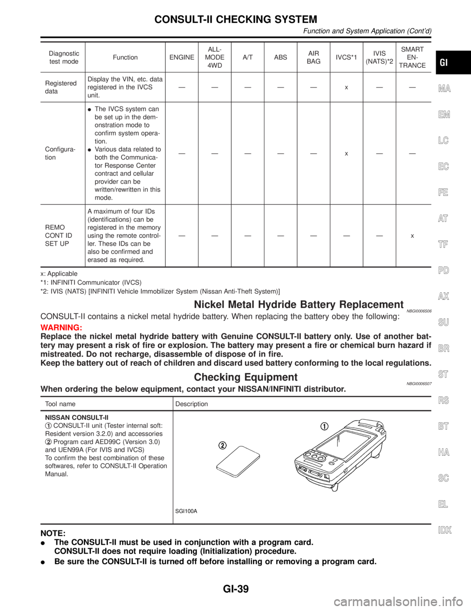
NISSAN CONSULT-II
q
1CONSULT-II unit (Tester internal soft:
Resident version 3.2.0) and accessories
q
2Program card AED99C (Version 3.0)
and UEN99A (For IVIS and IVCS)
To confirm the best combination of these
softwares, refer to CONSULT-II Operation
Manual.
SGI100A
NOTE:
IThe CONSULT-II must be used in conjunction with a program card.
CONSULT-II does not require loading (Initialization) procedure.
IBe sure the CONSULT-II is turned off before installing or removing a program card.
MA
EM
LC
EC
FE
AT
TF
PD
AX
SU
BR
ST
RS
BT
HA
SC
EL
IDX
CONSULT-II CHECKING SYSTEM
Function and System Application (Cont'd)
GI-39
Page 1792 of 2395

2-pole Lift=NBGI0008S03WARNING:
When lifting the vehicle, open the lift arms as wide as possible
and ensure that the front and rear of the vehicle are well bal-
anced.
When setting the lift arm, do not allow the arm to contact the
brake tubes, brake cable and fuel lines.
SGI133A
SGI988
Tow Truck TowingNBGI0008S04CAUTION:
IAll applicable state or Provincial (in Canada) laws and
local laws regarding the towing operation must be
obeyed.
IIt is necessary to use proper towing equipment to avoid
possible damage to the vehicle during towing operation.
Towing is in accordance with Towing Procedure Manual at
dealer.
IAlways attach safety chains before towing.
IWhen towing, make sure that the transmission, steering
system and power train are in good order. If any unit is
damaged, dollies must be used.
INever tow an automatic transmission model from the rear
(that is backward) with four wheels on the ground as this
may cause serious and expensive damage to the trans-
mission.
MA
EM
LC
EC
FE
AT
TF
PD
AX
SU
BR
ST
RS
BT
HA
SC
EL
IDX
LIFTING POINTS AND TOW TRUCK TOWING
2-pole Lift
GI-47
Page 1793 of 2395
SGI989
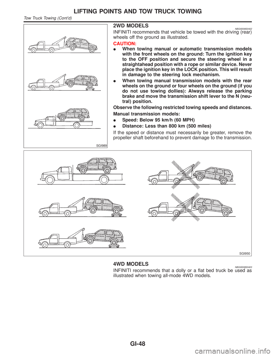
2WD MODELSNBGI0008S0402INFINITI recommends that vehicle be towed with the driving (rear)
wheels off the ground as illustrated.
CAUTION:
IWhen towing manual or automatic transmission models
with the front wheels on the ground: Turn the ignition key
to the OFF position and secure the steering wheel in a
straightahead position with a rope or similar device. Never
place the ignition key in the LOCK position. This will result
in damage to the steering lock mechanism.
IWhen towing manual transmission models with the rear
wheels on the ground or four wheels on the ground (if you
do not use towing dollies): Always release the parking
brake and move the transmission shift lever to the N (neu-
tral) position.
Observe the following restricted towing speeds and distances.
Manual transmission models:
ISpeed: Below 95 km/h (60 MPH)
IDistance: Less than 800 km (500 miles)
If the speed or distance must necessarily be greater, remove the
propeller shaft beforehand to prevent damage to the transmission.
SGI950
4WD MODELSNBGI0008S0403INFINITI recommends that a dolly or a flat bed truck be used as
illustrated when towing all-mode 4WD models.
LIFTING POINTS AND TOW TRUCK TOWING
Tow Truck Towing (Cont'd)
GI-48
Page 1795 of 2395
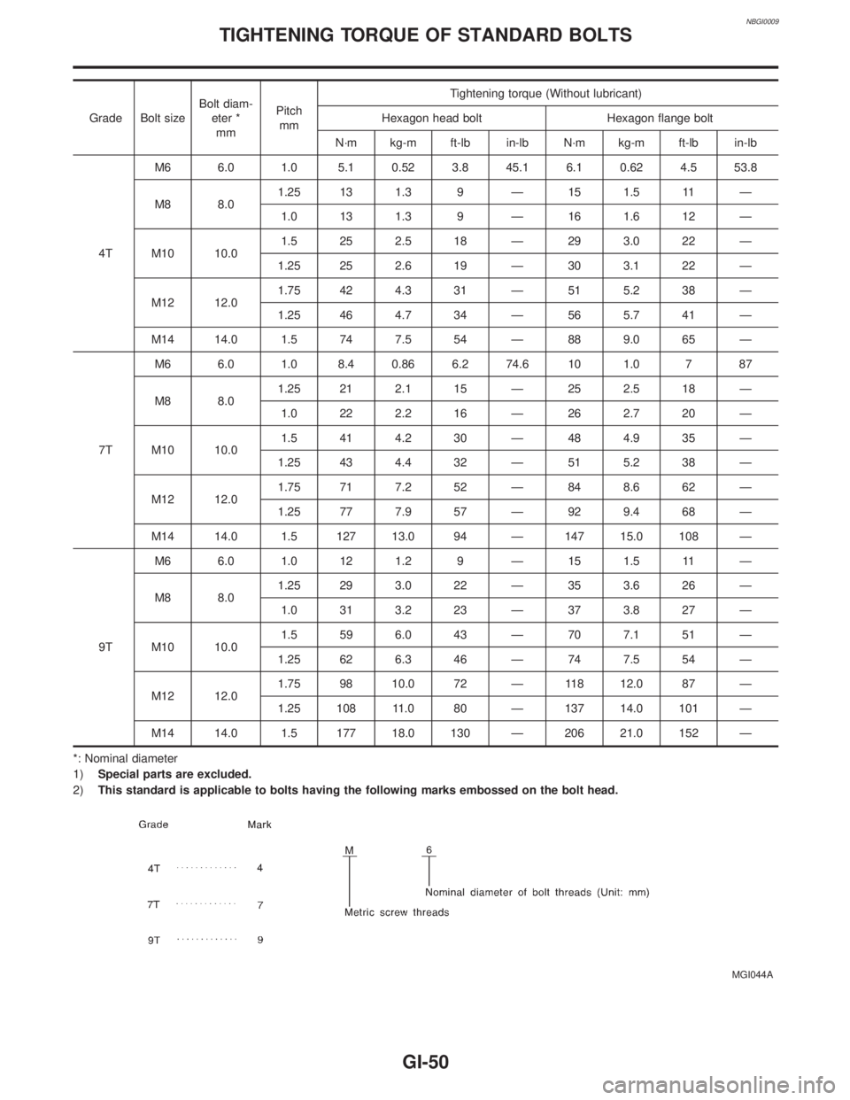
NBGI0009
Grade Bolt sizeBolt diam-
eter *
mmPitch
mmTightening torque (Without lubricant)
Hexagon head bolt Hexagon flange bolt
N´m kg-m ft-lb in-lb N´m kg-m ft-lb in-lb
4TM6 6.0 1.0 5.1 0.52 3.8 45.1 6.1 0.62 4.5 53.8
M8 8.01.25 13 1.3 9 Ð 15 1.5 11 Ð
1.0 13 1.3 9 Ð 16 1.6 12 Ð
M10 10.01.5 25 2.5 18 Ð 29 3.0 22 Ð
1.25 25 2.6 19 Ð 30 3.1 22 Ð
M12 12.01.75 42 4.3 31 Ð 51 5.2 38 Ð
1.25 46 4.7 34 Ð 56 5.7 41 Ð
M14 14.0 1.5 74 7.5 54 Ð 88 9.0 65 Ð
7TM6 6.0 1.0 8.4 0.86 6.2 74.6 10 1.0 7 87
M8 8.01.25 21 2.1 15 Ð 25 2.5 18 Ð
1.0 22 2.2 16 Ð 26 2.7 20 Ð
M10 10.01.5 41 4.2 30 Ð 48 4.9 35 Ð
1.25 43 4.4 32 Ð 51 5.2 38 Ð
M12 12.01.75 71 7.2 52 Ð 84 8.6 62 Ð
1.25 77 7.9 57 Ð 92 9.4 68 Ð
M14 14.0 1.5 127 13.0 94 Ð 147 15.0 108 Ð
9TM6 6.0 1.0 12 1.2 9 Ð 15 1.5 11 Ð
M8 8.01.25 29 3.0 22 Ð 35 3.6 26 Ð
1.0 31 3.2 23 Ð 37 3.8 27 Ð
M10 10.01.5 59 6.0 43 Ð 70 7.1 51 Ð
1.25 62 6.3 46 Ð 74 7.5 54 Ð
M12 12.01.75 98 10.0 72 Ð 118 12.0 87 Ð
1.25 108 11.0 80 Ð 137 14.0 101 Ð
M14 14.0 1.5 177 18.0 130 Ð 206 21.0 152 Ð
*: Nominal diameter
1)Special parts are excluded.
2)This standard is applicable to bolts having the following marks embossed on the bolt head.
MGI044A
TIGHTENING TORQUE OF STANDARD BOLTS
GI-50