2001 INFINITI QX4 vin
[x] Cancel search: vinPage 1408 of 2395
IA/T shift solenoid valve A
Coast OperationNBEL0216S0204When the SET/COAST switch is depressed during cruise control driving, ASCD actuator returns the throttle
cable to decrease vehicle set speed until the switch is released. And then ASCD will keep the new set speed.
Accel OperationNBEL0216S0205When the RESUME/ACCEL switch is depressed, power is supplied
Ifrom ASCD steering switch terminal 3
Ito ASCD control unit terminal 24.
If the RESUME/ACCEL switch is depressed during cruise control driving, ASCD actuator pulls the throttle cable
to increase the vehicle speed until the switch is released or vehicle speed is reached to maximum controlled
speed by the system. And then ASCD will keep the new set speed.
Cancel OperationNBEL0216S0206When any of following condition exists, cruise operation will be canceled.
ICANCEL switch is depressed. (Power supply to ASCD control unit terminals 11 and 24)
IBrake pedal is depressed. (Power supply to ASCD control unit terminal 23 from stop lamp switch)
IBrake pedal is depressed or A/T selector lever is shifted to P or N position. (Power supply to ASCD con-
trol unit terminal 8 is interrupted.)
If MAIN switch is turned to OFF during ASCD is activated, all of ASCD operation will be canceled and vehicle
speed memory will be erased.
Resume OperationNBEL0216S0207When the RESUME/ACCEL switch is depressed after cancel operation other than depressing MAIN switch is
performed, vehicle speed will return to last set speed. To resume vehicle set speed, vehicle condition must
meet following conditions.
IBrake pedal is released.
IA/T selector lever is in other than P and N position.
IVehicle speed is between 40 km/h (25 MPH) and 144 km/h (89 MPH).
ASCD PUMP OPERATIONNBEL0216S03The ASCD pump consists of a vacuum motor, an air valve and a release valve. When the ASCD activates,
power is supplied
Ifrom terminal 12 of ASCD control unit
Ito ASCD pump terminal 1.
Ground is supplied to vacuum motor, air valve and release valve from ASCD control unit depending on the
operated condition as shown in the below table.
The pump is connected to ASCD actuator by vacuum hose. When the ASCD pump is activated, the ASCD
pump vacuum the diaphragm of ASCD actuator to control throttle cable.
Air valve (*1) Release valve (*1) Vacuum motorActuator inner pres-
sure
ASCD not operating Open Open Stopped Atmosphere
ASCD operatingReleasing throttle
cableOpen Closed Stopped Vacuum
Holding throttle
positionClosed Closed Stopped Vacuum (*2)
Pulling throttle cable Closed Closed Operated Vacuum
*1: When power and ground is supplied, valve is closed.
*2: Set position held.
GI
MA
EM
LC
EC
FE
AT
TF
PD
AX
SU
BR
ST
RS
BT
HA
SC
IDX
AUTOMATIC SPEED CONTROL DEVICE (ASCD)
System Description (Cont'd)
EL-223
Page 1425 of 2395
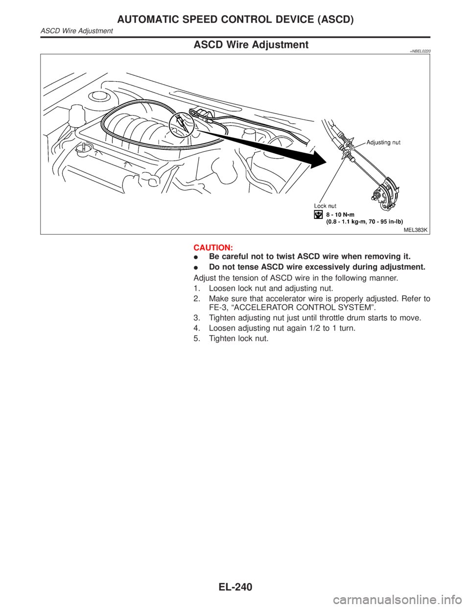
ASCD Wire Adjustment=NBEL0220
MEL383K
CAUTION:
IBe careful not to twist ASCD wire when removing it.
IDo not tense ASCD wire excessively during adjustment.
Adjust the tension of ASCD wire in the following manner.
1. Loosen lock nut and adjusting nut.
2. Make sure that accelerator wire is properly adjusted. Refer to
FE-3, ªACCELERATOR CONTROL SYSTEMº.
3. Tighten adjusting nut just until throttle drum starts to move.
4. Loosen adjusting nut again 1/2 to 1 turn.
5. Tighten lock nut.
AUTOMATIC SPEED CONTROL DEVICE (ASCD)
ASCD Wire Adjustment
EL-240
Page 1533 of 2395
PrecautionNBEL0177CAUTION:
IUse CONSULT-II to set the system ªDemonstration modeº if INFINITI Communicator needs to be
activated during service procedures. (For details of the demonstration mode, refer to EL-379.)
IMake sure to turn the demonstration mode OFF before returning the vehicle to the owner.
IIn the demonstration mode, no service from the Communicator Response Center is available.
Therefore, even if the customer encounters an emergency, no service will be dispatched.
IIf the theft warning system is activated for more than 7 seconds, INFINITI Communicator will dial
to the Communicator Response Center automatically. The operator will contact the customer to
confirm whether the vehicle has been stolen or not.
IWhen ªMaydayº emergency dialing is activated (if the system is not in the demonstration mode),
the Communicator Response Center operator will come online. If there is no emergency, the
operator will ask the occupant for the user password (option). Failure to provide the correct pass-
word results in a police response.
IIVCS unit memory includes VIN (Vehicle Identification Number) and other such vehicle specific
data. Therefore, the IVCS unit cannot be transferred to another vehicle. When the IVCS unit is
replaced, the new unit must be set up and programmed. The INFINITI Communicator system auto-
matically contacts the Communicator Response Center the first time the vehicle is started after a
phone number has been changed or a module (IVCS unit) is replaced. The VIN will be written in
the memory of the new unit by transmitting data from the Communicator Response Center. For
details, refer to ªSystem Settingº, EL-381.
IBefore servicing the vehicle, confirm that the VIN memorized by the IVCS unit is the same as the
VIN on the vehicle's identification plate.
Communicator Response Center Telephone
Number for Technicians
NBEL0178The Communicator Response Center telephone number for technicians is1-888-427-4812.
Whenever an INFINITI dealer technician dials the above number, the following information will be required by
the Communicator Response Center operator.
ICustomer name
IUnit ID number of old IVCS unit (For details, refer to EL-367.)
IUnit ID number of new IVCS unit
IVIN
IDealer name and code (For security purposes)
IDealer contact person (technician)
IDealer phone and fax numbers
INFINITI COMMUNICATOR (IVCS)
Precaution
EL-348
Page 1540 of 2395
greatly depending on the cellular network and cellular signal
strength. The system resets to ready when the system com-
pletes the dialing attempts. The vehicle owner can press the
button again if he or she still needs to contact the Communi-
cator Response Center.
IINFINITI Communicator automatically redials if communication
between the vehicle owner and Communicator Response Cen-
ter is lost for some reason.
IThe only way for a transmission to be officially terminated is for
the Communicator Response Center to send an end transmis-
sion signal, which turns off the indicator in the switch. (Com-
munication with Communicator Response Center can not be
terminated by the occupant.)
IIf the vehicle owner start the engine during a call, the conver-
sation may be interrupted. When this happens the system may
try to resume transmission once after the engine has been
started.
SEL526V
GPS (GLOBAL POSITIONING SYSTEM)NBEL0180S09GPS is the global positioning system developed and operated by
the US Department of Defense. GPS satellites (NAVSTAR) trans-
mit radio waves and orbit around the earth at an altitude of approxi-
mately 21,000 km (13,000 miles).
GPS receiver calculates the three-dimensional position of the
vehicle (latitude, longitude, and altitude from the sea level) by the
time difference of the radio wave arriving from more than four GPS
satellites (three-dimensional positioning).
When the radio wave is received from only three GPS satellites, the
two-dimensional position (latitude and longitude) is calculated,
using the altitude from the sea level data calculated by using four
GPS satellites (two-dimensional positioning).
Positioning capability is degraded in the following cases.
IIn two-dimensional positioning, when the vehicle's altitude
from the sea level changes, the precision becomes lower.
IThe location detection performance can have an error of about
100 m (300 ft) even in three-dimensional positioning with high
precision. Because the precision is influenced by the location
of GPS satellites used for positioning, the location detection
performance may drop depending on the location of GPS sat-
ellites.
IWhen the radio wave from GPS satellites cannot be received,
for example, when the vehicle is in a tunnel, in a parking lot
inside building, under an elevated superhighway or near strong
power lines, the location may not be detected. Turbulent/
electric weather conditions may also affect positioning perfor-
mance. If something is placed on the antenna, the radio wave
from GPS satellites may not be received.
GI
MA
EM
LC
EC
FE
AT
TF
PD
AX
SU
BR
ST
RS
BT
HA
SC
IDX
INFINITI COMMUNICATOR (IVCS)
System Description (Cont'd)
EL-355
Page 1549 of 2395
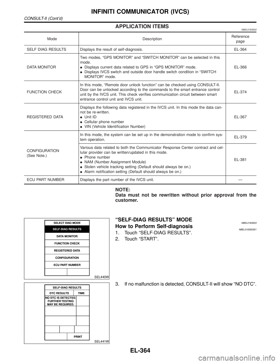
APPLICATION ITEMSNBEL0183S02
Mode DescriptionReference
page
SELF DIAG RESULTS Displays the result of self-diagnosis. EL-364
DATA MONITORTwo modes, ªGPS MONITORº and ªSWITCH MONITORº can be selected in this
mode.
IDisplays current data related to GPS in ªGPS MONITORº mode.
IDisplays IVCS switch and outside door handle switch condition in ªSWITCH
MONITORº mode.EL-366
FUNCTION CHECKIn this mode, ªRemote door unlock functionº can be checked using CONSULT-II.
Door can be unlocked according to the commands to the smart entrance control
unit by the IVCS unit. This check verifies communication circuit between smart
entrance control unit and IVCS unit.EL-374
REGISTERED DATADisplays the following data registered in the IVCS unit. In this mode the data can-
not be re-written.
IUnit ID
ICellular phone number
IVIN (Vehicle Identification Number)EL-367
CONFIGURATION
(See Note.)In this mode, the system can be set up in the demonstration mode to confirm sys-
tem operation.EL-379
Various data related to both the Communicator Response Center contract and cel-
lular provider can be written/updated in this mode.
IPhone number
INAM (Number Assignment Module)
IStolen vehicle tracking setting (Default should always be on.)
IAlarm notification setting (Default should always be on.)EL-381
ECU PART NUMBER Displays the part number of the IVCS unit. Ð
NOTE:
Data must not be rewritten without prior approval from the
customer.
SEL440W
ªSELF-DIAG RESULTSº MODENBEL0183S03How to Perform Self-diagnosisNBEL0183S03011. Touch ªSELF-DIAG RESULTSº.
2. Touch ªSTARTº.
SEL441W
3. If no malfunction is detected, CONSULT-II will show ªNO DTCº.
INFINITI COMMUNICATOR (IVCS)
CONSULT-II (Cont'd)
EL-364
Page 1552 of 2395

SEL445W
ªREGISTERED DATAº MODENBEL0183S05
Item Description
UNIT IDID number of the IVCS unit. ID number is unique to
each unit and differs for each unit.
CELLULAR PHONE # Ð
VIN #Vehicle Identification Number. When the IVCS unit is
replaced, VIN # is written in the memory of the
replaced unit by transmitting data from the Communi-
cator Response Center.
NOTE:
No data can be changed in this CONSULT-II mode.
GI
MA
EM
LC
EC
FE
AT
TF
PD
AX
SU
BR
ST
RS
BT
HA
SC
IDX
INFINITI COMMUNICATOR (IVCS)
CONSULT-II (Cont'd)
EL-367
Page 1572 of 2395
SEL685V
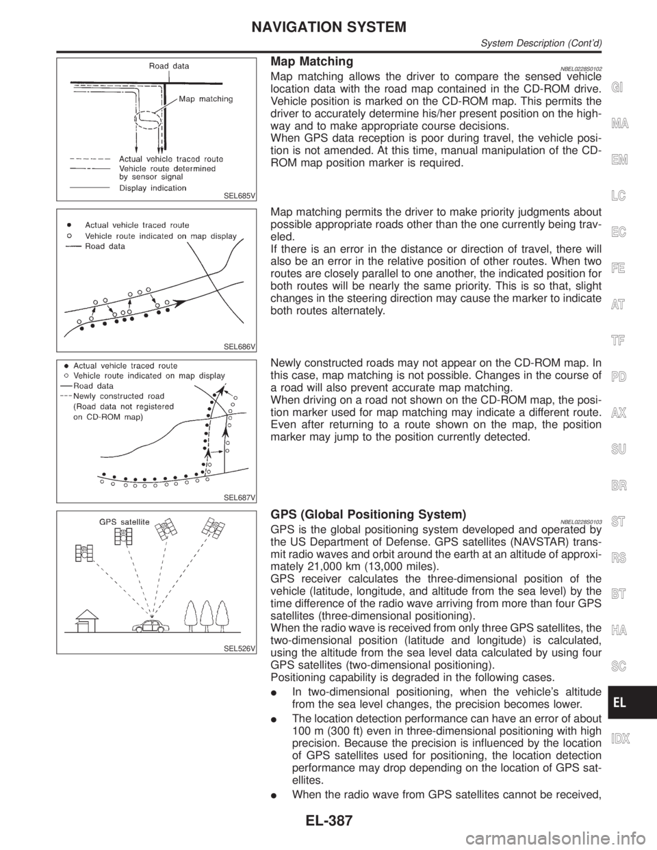
Map MatchingNBEL0228S0102Map matching allows the driver to compare the sensed vehicle
location data with the road map contained in the CD-ROM drive.
Vehicle position is marked on the CD-ROM map. This permits the
driver to accurately determine his/her present position on the high-
way and to make appropriate course decisions.
When GPS data reception is poor during travel, the vehicle posi-
tion is not amended. At this time, manual manipulation of the CD-
ROM map position marker is required.
SEL686V
Map matching permits the driver to make priority judgments about
possible appropriate roads other than the one currently being trav-
eled.
If there is an error in the distance or direction of travel, there will
also be an error in the relative position of other routes. When two
routes are closely parallel to one another, the indicated position for
both routes will be nearly the same priority. This is so that, slight
changes in the steering direction may cause the marker to indicate
both routes alternately.
SEL687V
Newly constructed roads may not appear on the CD-ROM map. In
this case, map matching is not possible. Changes in the course of
a road will also prevent accurate map matching.
When driving on a road not shown on the CD-ROM map, the posi-
tion marker used for map matching may indicate a different route.
Even after returning to a route shown on the map, the position
marker may jump to the position currently detected.
SEL526V
GPS (Global Positioning System)NBEL0228S0103GPS is the global positioning system developed and operated by
the US Department of Defense. GPS satellites (NAVSTAR) trans-
mit radio waves and orbit around the earth at an altitude of approxi-
mately 21,000 km (13,000 miles).
GPS receiver calculates the three-dimensional position of the
vehicle (latitude, longitude, and altitude from the sea level) by the
time difference of the radio wave arriving from more than four GPS
satellites (three-dimensional positioning).
When the radio wave is received from only three GPS satellites, the
two-dimensional position (latitude and longitude) is calculated,
using the altitude from the sea level data calculated by using four
GPS satellites (two-dimensional positioning).
Positioning capability is degraded in the following cases.
IIn two-dimensional positioning, when the vehicle's altitude
from the sea level changes, the precision becomes lower.
IThe location detection performance can have an error of about
100 m (300 ft) even in three-dimensional positioning with high
precision. Because the precision is influenced by the location
of GPS satellites used for positioning, the location detection
performance may drop depending on the location of GPS sat-
ellites.
IWhen the radio wave from GPS satellites cannot be received,
GI
MA
EM
LC
EC
FE
AT
TF
PD
AX
SU
BR
ST
RS
BT
HA
SC
IDX
NAVIGATION SYSTEM
System Description (Cont'd)
EL-387
Page 1573 of 2395
for example, when the vehicle is in a tunnel, in a parking lot
inside building, under an elevated superhighway or near strong
power lines, the location may not be detected. Turbulent/
electric weather conditions may also affect positioning perfor-
mance. If something is placed on the antenna, the radio wave
from GPS satellites may not be received.
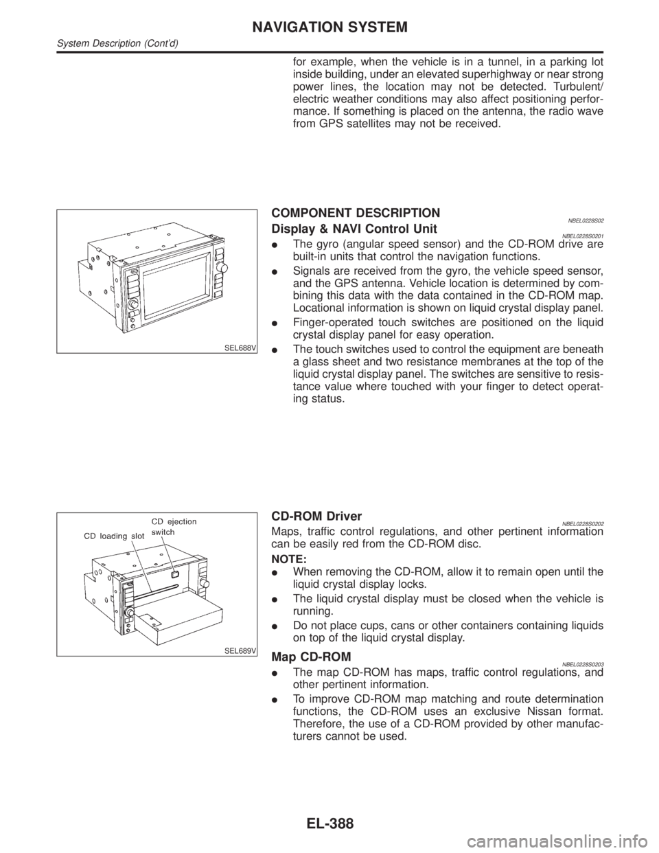
SEL688V
COMPONENT DESCRIPTIONNBEL0228S02Display & NAVI Control UnitNBEL0228S0201IThe gyro (angular speed sensor) and the CD-ROM drive are
built-in units that control the navigation functions.
ISignals are received from the gyro, the vehicle speed sensor,
and the GPS antenna. Vehicle location is determined by com-
bining this data with the data contained in the CD-ROM map.
Locational information is shown on liquid crystal display panel.
IFinger-operated touch switches are positioned on the liquid
crystal display panel for easy operation.
IThe touch switches used to control the equipment are beneath
a glass sheet and two resistance membranes at the top of the
liquid crystal display panel. The switches are sensitive to resis-
tance value where touched with your finger to detect operat-
ing status.
SEL689V
CD-ROM DriverNBEL0228S0202Maps, traffic control regulations, and other pertinent information
can be easily red from the CD-ROM disc.
NOTE:
IWhen removing the CD-ROM, allow it to remain open until the
liquid crystal display locks.
IThe liquid crystal display must be closed when the vehicle is
running.
IDo not place cups, cans or other containers containing liquids
on top of the liquid crystal display.
Map CD-ROMNBEL0228S0203IThe map CD-ROM has maps, traffic control regulations, and
other pertinent information.
ITo improve CD-ROM map matching and route determination
functions, the CD-ROM uses an exclusive Nissan format.
Therefore, the use of a CD-ROM provided by other manufac-
turers cannot be used.
NAVIGATION SYSTEM
System Description (Cont'd)
EL-388