2001 INFINITI QX4 vin
[x] Cancel search: vinPage 1026 of 2395
On Board Diagnosis LogicNBEC0282HThe closed loop control has the one trip detection logic.
Malfunction is detected when the closed loop control function for
right bank does not operate even when vehicle is driving in the
specified condition, the closed loop control function for left bank
does not operate even when vehicle is driving in the specified
condition.
Possible CauseNBEC0531IThe front heated oxygen sensor circuit is open or shorted.
IHeated oxygen sensor 1 (front)
IHeated oxygen sensor 1 heater (front)
DTC Confirmation ProcedureNBEC0283CAUTION:
Always drive vehicle at a safe speed.
NOTE:
If ªDTC Confirmation Procedureº has been previously conducted,
always turn ignition switch ªOFFº and wait at least 10 seconds
before conducting the next test.
TESTING CONDITION:
INever raise engine speed above 3,600 rpm during the
ªDTC Confirmation Procedureº. If the engine speed limit is
exceeded, retry the procedure from step 2.
IBefore performing the following procedure, confirm that
battery voltage is more than 11V at idle.
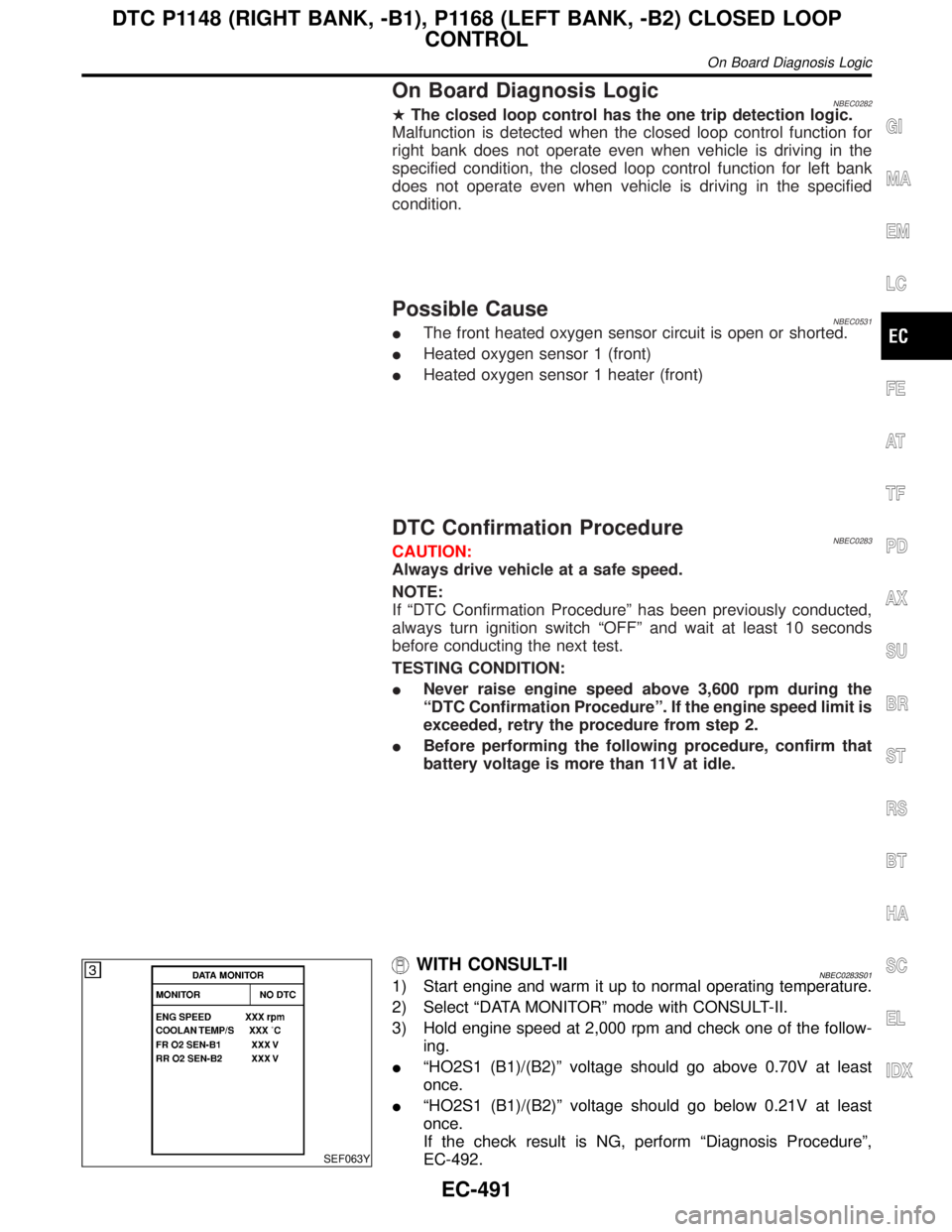
SEF063Y
WITH CONSULT-IINBEC0283S011) Start engine and warm it up to normal operating temperature.
2) Select ªDATA MONITORº mode with CONSULT-II.
3) Hold engine speed at 2,000 rpm and check one of the follow-
ing.
IªHO2S1 (B1)/(B2)º voltage should go above 0.70V at least
once.
IªHO2S1 (B1)/(B2)º voltage should go below 0.21V at least
once.
If the check result is NG, perform ªDiagnosis Procedureº,
EC-492.
GI
MA
EM
LC
FE
AT
TF
PD
AX
SU
BR
ST
RS
BT
HA
SC
EL
IDX
DTC P1148 (RIGHT BANK, -B1), P1168 (LEFT BANK, -B2) CLOSED LOOP
CONTROL
On Board Diagnosis Logic
EC-491
Page 1070 of 2395
11 CHECK EVAP CANISTER
Weigh the EVAP canister with the EVAP canister vent control valve attached.
The weight should be less than 1.8 kg (4.0 lb).
OK or NG
OK (With CONSULT-II)©GO TO 13.
OK (Without CONSULT-
II)©GO TO 14.
NG©GO TO 12.
12 DETECT MALFUNCTIONING PART
Check the following.
IEVAP canister for damage
IEVAP hose between EVAP canister and water separator for clogging or poor connection
©Repair hose or replace EVAP canister.
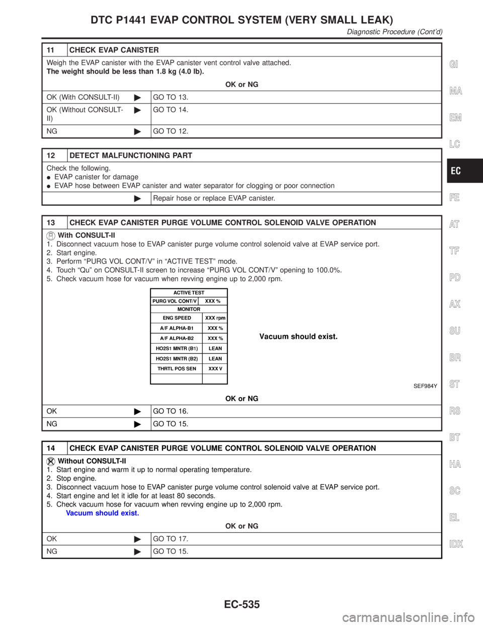
13 CHECK EVAP CANISTER PURGE VOLUME CONTROL SOLENOID VALVE OPERATION
With CONSULT-II
1. Disconnect vacuum hose to EVAP canister purge volume control solenoid valve at EVAP service port.
2. Start engine.
3. Perform ªPURG VOL CONT/Vº in ªACTIVE TESTº mode.
4. Touch ªQuº on CONSULT-II screen to increase ªPURG VOL CONT/Vº opening to 100.0%.
5. Check vacuum hose for vacuum when revving engine up to 2,000 rpm.
SEF984Y
OK or NG
OK©GO TO 16.
NG©GO TO 15.
14 CHECK EVAP CANISTER PURGE VOLUME CONTROL SOLENOID VALVE OPERATION
Without CONSULT-II
1. Start engine and warm it up to normal operating temperature.
2. Stop engine.
3. Disconnect vacuum hose to EVAP canister purge volume control solenoid valve at EVAP service port.
4. Start engine and let it idle for at least 80 seconds.
5. Check vacuum hose for vacuum when revving engine up to 2,000 rpm.
Vacuum should exist.
OK or NG
OK©GO TO 17.
NG©GO TO 15.
GI
MA
EM
LC
FE
AT
TF
PD
AX
SU
BR
ST
RS
BT
HA
SC
EL
IDX
DTC P1441 EVAP CONTROL SYSTEM (VERY SMALL LEAK)
Diagnostic Procedure (Cont'd)
EC-535
Page 1077 of 2395
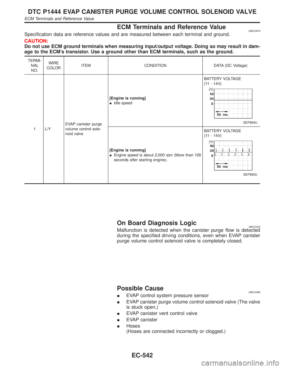
ECM Terminals and Reference ValueNBEC0678Specification data are reference values and are measured between each terminal and ground.
CAUTION:
Do not use ECM ground terminals when measuring input/output voltage. Doing so may result in dam-
age to the ECM's transistor. Use a ground other than ECM terminals, such as the ground.
TERMI-
NAL
NO.WIRE
COLORITEM CONDITION DATA (DC Voltage)
1 L/YEVAP canister purge
volume control sole-
noid valve[Engine is running]
IIdle speedBATTERY VOLTAGE
(11 - 14V)
SEF994U
[Engine is running]
IEngine speed is about 2,000 rpm (More than 100
seconds after starting engine).BATTERY VOLTAGE
(11 - 14V)
SEF995U
On Board Diagnosis LogicNBEC0322Malfunction is detected when the canister purge flow is detected
during the specified driving conditions, even when EVAP canister
purge volume control solenoid valve is completely closed.
Possible CauseNBEC0588IEVAP control system pressure sensor
IEVAP canister purge volume control solenoid valve (The valve
is stuck open.)
IEVAP canister vent control valve
IEVAP canister
IHoses
(Hoses are connected incorrectly or clogged.)
DTC P1444 EVAP CANISTER PURGE VOLUME CONTROL SOLENOID VALVE
ECM Terminals and Reference Value
EC-542
Page 1088 of 2395
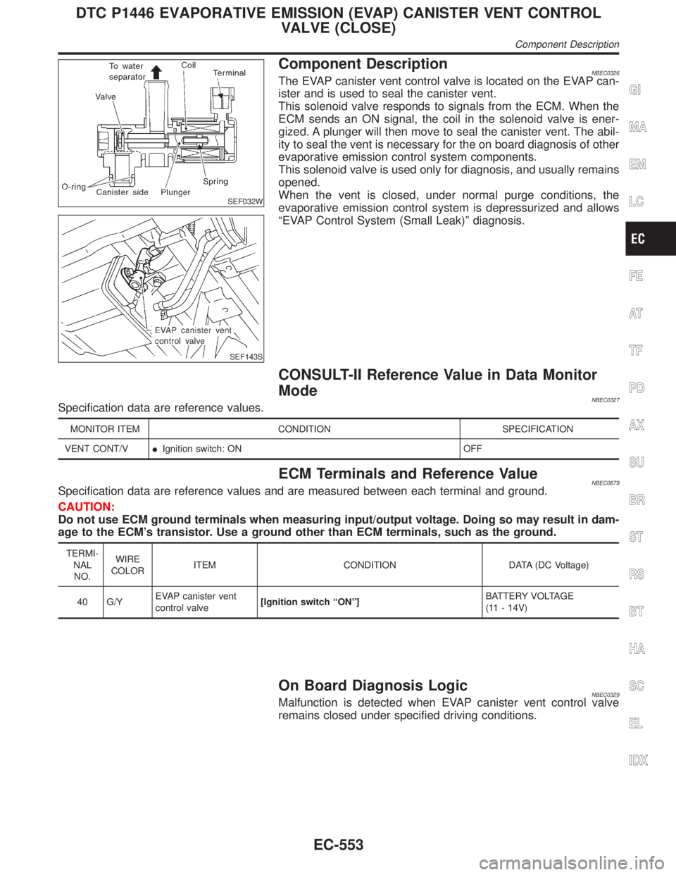
SEF032W
SEF143S
Component DescriptionNBEC0326The EVAP canister vent control valve is located on the EVAP can-
ister and is used to seal the canister vent.
This solenoid valve responds to signals from the ECM. When the
ECM sends an ON signal, the coil in the solenoid valve is ener-
gized. A plunger will then move to seal the canister vent. The abil-
ity to seal the vent is necessary for the on board diagnosis of other
evaporative emission control system components.
This solenoid valve is used only for diagnosis, and usually remains
opened.
When the vent is closed, under normal purge conditions, the
evaporative emission control system is depressurized and allows
ªEVAP Control System (Small Leak)º diagnosis.
CONSULT-II Reference Value in Data Monitor
Mode
NBEC0327Specification data are reference values.
MONITOR ITEM CONDITION SPECIFICATION
VENT CONT/VIIgnition switch: ON OFF
ECM Terminals and Reference ValueNBEC0679Specification data are reference values and are measured between each terminal and ground.
CAUTION:
Do not use ECM ground terminals when measuring input/output voltage. Doing so may result in dam-
age to the ECM's transistor. Use a ground other than ECM terminals, such as the ground.
TERMI-
NAL
NO.WIRE
COLORITEM CONDITION DATA (DC Voltage)
40 G/YEVAP canister vent
control valve[Ignition switch ªONº]BATTERY VOLTAGE
(11 - 14V)
On Board Diagnosis LogicNBEC0329Malfunction is detected when EVAP canister vent control valve
remains closed under specified driving conditions.
GI
MA
EM
LC
FE
AT
TF
PD
AX
SU
BR
ST
RS
BT
HA
SC
EL
IDX
DTC P1446 EVAPORATIVE EMISSION (EVAP) CANISTER VENT CONTROL
VALVE (CLOSE)
Component Description
EC-553
Page 1100 of 2395
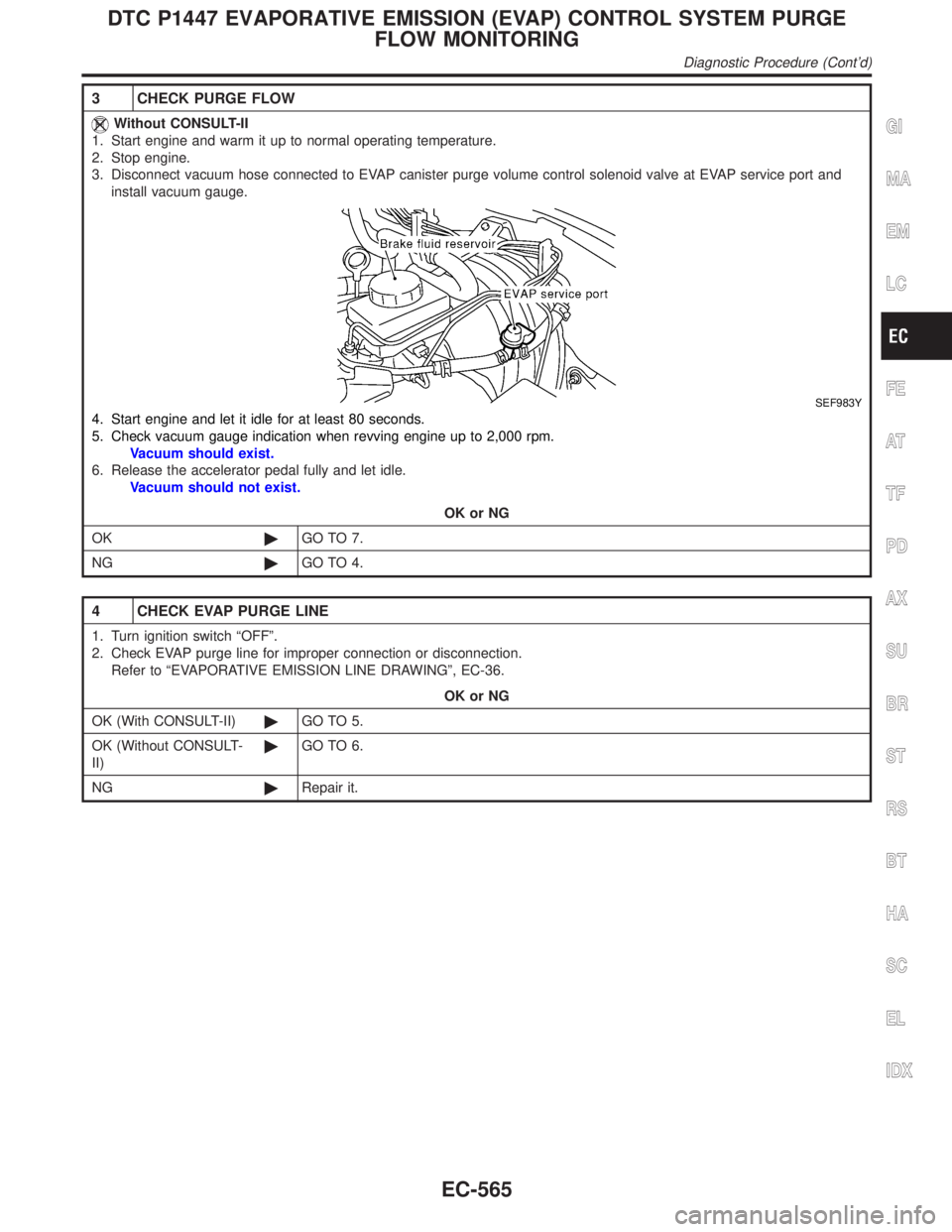
3 CHECK PURGE FLOW
Without CONSULT-II
1. Start engine and warm it up to normal operating temperature.
2. Stop engine.
3. Disconnect vacuum hose connected to EVAP canister purge volume control solenoid valve at EVAP service port and
install vacuum gauge.
SEF983Y
4. Start engine and let it idle for at least 80 seconds.
5. Check vacuum gauge indication when revving engine up to 2,000 rpm.
Vacuum should exist.
6. Release the accelerator pedal fully and let idle.
Vacuum should not exist.
OK or NG
OK©GO TO 7.
NG©GO TO 4.
4 CHECK EVAP PURGE LINE
1. Turn ignition switch ªOFFº.
2. Check EVAP purge line for improper connection or disconnection.
Refer to ªEVAPORATIVE EMISSION LINE DRAWINGº, EC-36.
OK or NG
OK (With CONSULT-II)©GO TO 5.
OK (Without CONSULT-
II)©GO TO 6.
NG©Repair it.
GI
MA
EM
LC
FE
AT
TF
PD
AX
SU
BR
ST
RS
BT
HA
SC
EL
IDX
DTC P1447 EVAPORATIVE EMISSION (EVAP) CONTROL SYSTEM PURGE
FLOW MONITORING
Diagnostic Procedure (Cont'd)
EC-565
Page 1108 of 2395
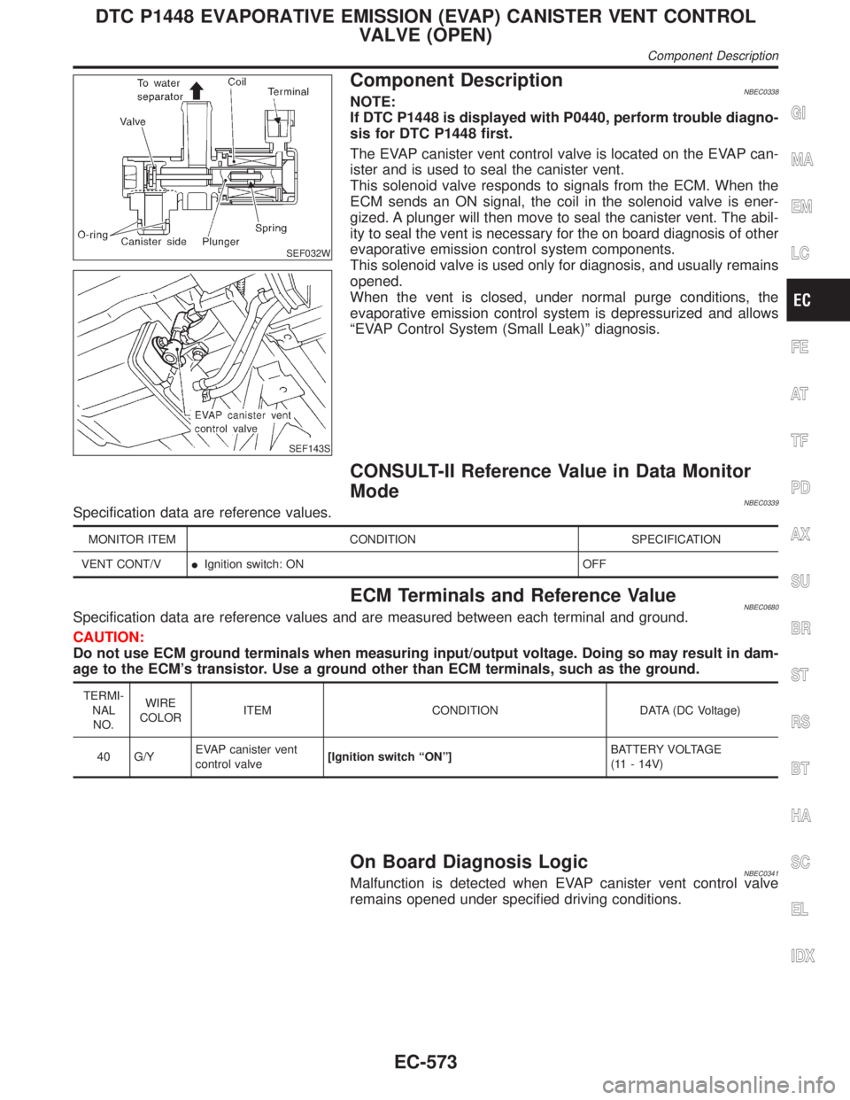
SEF032W
SEF143S
Component DescriptionNBEC0338NOTE:
If DTC P1448 is displayed with P0440, perform trouble diagno-
sis for DTC P1448 first.
The EVAP canister vent control valve is located on the EVAP can-
ister and is used to seal the canister vent.
This solenoid valve responds to signals from the ECM. When the
ECM sends an ON signal, the coil in the solenoid valve is ener-
gized. A plunger will then move to seal the canister vent. The abil-
ity to seal the vent is necessary for the on board diagnosis of other
evaporative emission control system components.
This solenoid valve is used only for diagnosis, and usually remains
opened.
When the vent is closed, under normal purge conditions, the
evaporative emission control system is depressurized and allows
ªEVAP Control System (Small Leak)º diagnosis.
CONSULT-II Reference Value in Data Monitor
Mode
NBEC0339Specification data are reference values.
MONITOR ITEM CONDITION SPECIFICATION
VENT CONT/VIIgnition switch: ON OFF
ECM Terminals and Reference ValueNBEC0680Specification data are reference values and are measured between each terminal and ground.
CAUTION:
Do not use ECM ground terminals when measuring input/output voltage. Doing so may result in dam-
age to the ECM's transistor. Use a ground other than ECM terminals, such as the ground.
TERMI-
NAL
NO.WIRE
COLORITEM CONDITION DATA (DC Voltage)
40 G/YEVAP canister vent
control valve[Ignition switch ªONº]BATTERY VOLTAGE
(11 - 14V)
On Board Diagnosis LogicNBEC0341Malfunction is detected when EVAP canister vent control valve
remains opened under specified driving conditions.
GI
MA
EM
LC
FE
AT
TF
PD
AX
SU
BR
ST
RS
BT
HA
SC
EL
IDX
DTC P1448 EVAPORATIVE EMISSION (EVAP) CANISTER VENT CONTROL
VALVE (OPEN)
Component Description
EC-573
Page 1139 of 2395
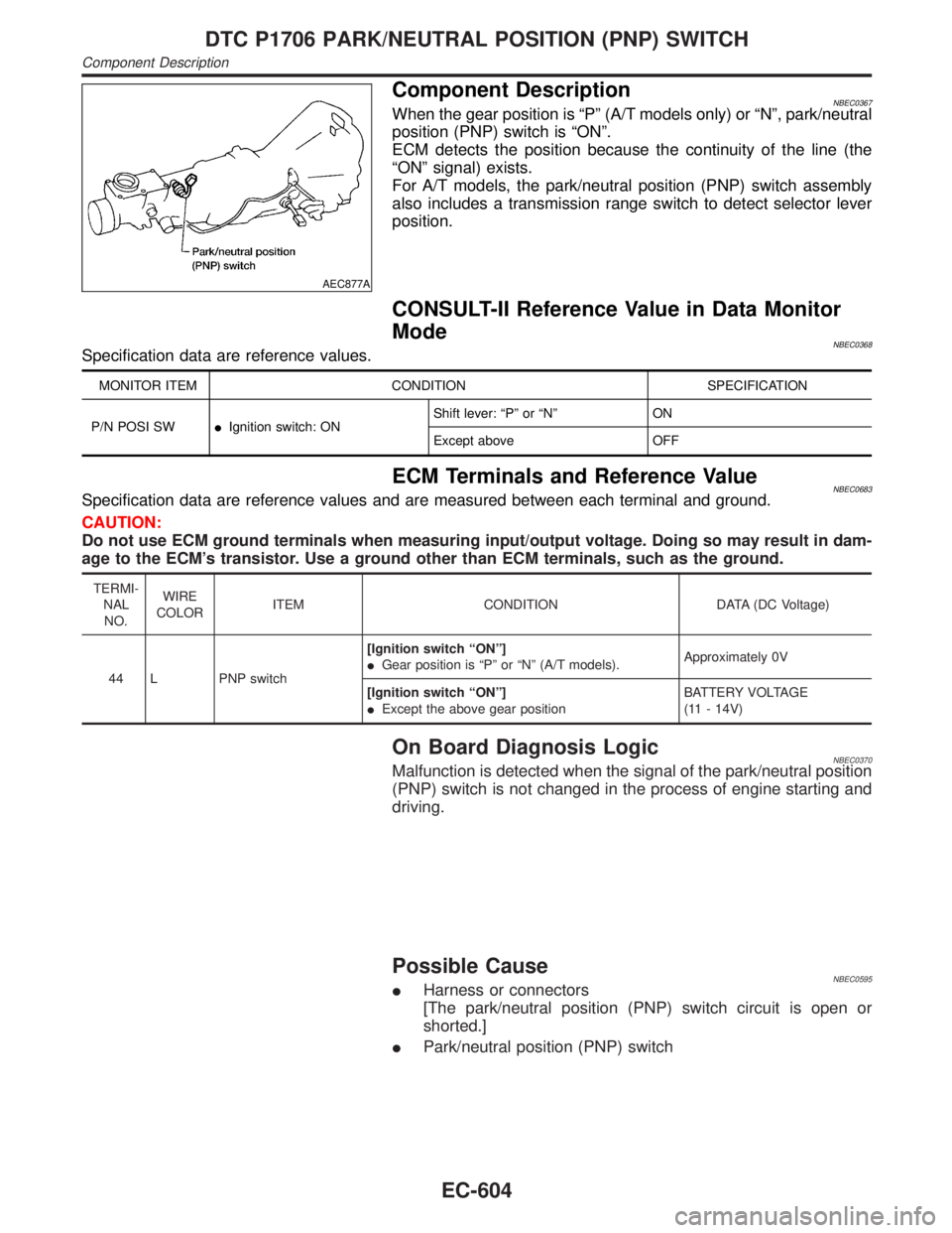
AEC877A
Component DescriptionNBEC0367When the gear position is ªPº (A/T models only) or ªNº, park/neutral
position (PNP) switch is ªONº.
ECM detects the position because the continuity of the line (the
ªONº signal) exists.
For A/T models, the park/neutral position (PNP) switch assembly
also includes a transmission range switch to detect selector lever
position.
CONSULT-II Reference Value in Data Monitor
Mode
NBEC0368Specification data are reference values.
MONITOR ITEM CONDITION SPECIFICATION
P/N POSI SWIIgnition switch: ONShift lever: ªPº or ªNº ON
Except above OFF
ECM Terminals and Reference ValueNBEC0683Specification data are reference values and are measured between each terminal and ground.
CAUTION:
Do not use ECM ground terminals when measuring input/output voltage. Doing so may result in dam-
age to the ECM's transistor. Use a ground other than ECM terminals, such as the ground.
TERMI-
NAL
NO.WIRE
COLORITEM CONDITION DATA (DC Voltage)
44 L PNP switch[Ignition switch ªONº]
IGear position is ªPº or ªNº (A/T models).Approximately 0V
[Ignition switch ªONº]
IExcept the above gear positionBATTERY VOLTAGE
(11 - 14V)
On Board Diagnosis LogicNBEC0370Malfunction is detected when the signal of the park/neutral position
(PNP) switch is not changed in the process of engine starting and
driving.
Possible CauseNBEC0595IHarness or connectors
[The park/neutral position (PNP) switch circuit is open or
shorted.]
IPark/neutral position (PNP) switch
DTC P1706 PARK/NEUTRAL POSITION (PNP) SWITCH
Component Description
EC-604
Page 1160 of 2395
System DescriptionNBEC0392
Sensor Input Signal to ECMECM func-
tionActuator
Crankshaft position sensor (POS) Engine speed (POS signal)
Fuel pump
controlFuel pump relay Crankshaft position sensor (REF) Engine speed (REF signal)
Ignition switch Start signal
The ECM activates the fuel pump for several seconds after the ignition switch is turned on to improve engine
startability. If the ECM receives a 120É signal from the crankshaft position sensor (REF), it knows that the
engine is rotating, and causes the pump to operate. If the 120É signal is not received when the ignition switch
is on, the engine stalls. The ECM stops pump operation and prevents battery discharging, thereby improving
safety. The ECM does not directly drive the fuel pump. It controls the ON/OFF fuel pump relay, which in turn
controls the fuel pump.
Condition Fuel pump operation
Ignition switch is turned to ON. Operates for 1 second.
Engine running and cranking Operates.
When engine is stopped Stops in 1.5 seconds.
Except as shown aboveStops.
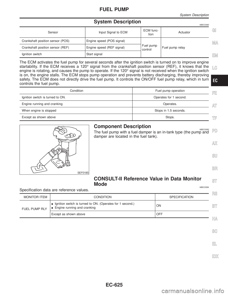
SEF018S
Component DescriptionNBEC0393The fuel pump with a fuel damper is an in-tank type (the pump and
damper are located in the fuel tank).
CONSULT-II Reference Value in Data Monitor
Mode
NBEC0394Specification data are reference values.
MONITOR ITEM CONDITION SPECIFICATION
FUEL PUMP RLYIIgnition switch is turned to ON. (Operates for 1 second.)
IEngine running and crankingON
Except as shown above OFF
GI
MA
EM
LC
FE
AT
TF
PD
AX
SU
BR
ST
RS
BT
HA
SC
EL
IDX
FUEL PUMP
System Description
EC-625