2001 INFINITI QX4 vin
[x] Cancel search: vinPage 1201 of 2395

CEL083
InspectionNBEL0007FUSENBEL0007S01IIf fuse is blown, be sure to eliminate cause of problem
before installing new fuse.
IUse fuse of specified rating. Never use fuse of more than
specified rating.
IDo not partially install fuse; always insert it into fuse
holder properly.
IRemove fuse for ªELECTRICAL PARTS (BAT)º if vehicle is
not used for a long period of time.
MEL944F
FUSIBLE LINKNBEL0007S02A melted fusible link can be detected either by visual inspection or
by feeling with finger tip. If its condition is questionable, use circuit
tester or test lamp.
CAUTION:
IIf fusible link should melt, it is possible that critical circuit
(power supply or large current carrying circuit) is shorted.
In such a case, carefully check and eliminate cause of
problem.
INever wrap outside of fusible link with vinyl tape. Impor-
tant: Never let fusible link touch any other wiring harness,
vinyl or rubber parts.
SEL109W
CIRCUIT BREAKER (PTC THERMISTOR TYPE)NBEL0007S03The PTC thermister generates heat in response to current flow.
The temperature (and resistance) of the thermister element varies
with current flow. Excessive current flow will cause the element's
temperature to rise. When the temperature reaches a specified
level, the electrical resistance will rise sharply to control the circuit
current.
Reduced current flow will cause the element to cool. Resistance
falls accordingly and normal circuit current flow is allowed to
resume.
POWER SUPPLY ROUTING
Inspection
EL-16
Page 1214 of 2395
MEL304D
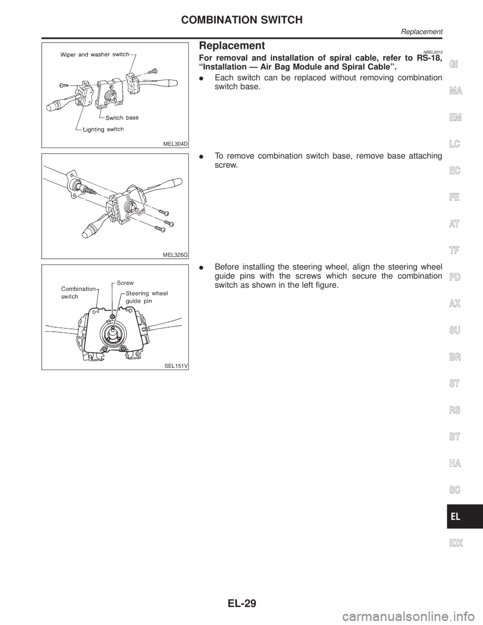
ReplacementNBEL0010For removal and installation of spiral cable, refer to RS-18,
ªInstallation Ð Air Bag Module and Spiral Cableº.
IEach switch can be replaced without removing combination
switch base.
MEL326G
ITo remove combination switch base, remove base attaching
screw.
SEL151V
IBefore installing the steering wheel, align the steering wheel
guide pins with the screws which secure the combination
switch as shown in the left figure.
GI
MA
EM
LC
EC
FE
AT
TF
PD
AX
SU
BR
ST
RS
BT
HA
SC
IDX
COMBINATION SWITCH
Replacement
EL-29
Page 1225 of 2395
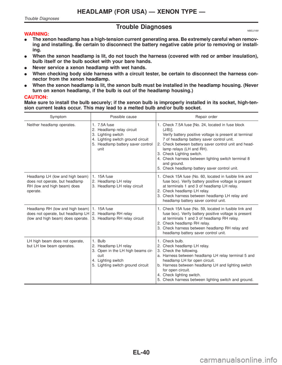
Trouble DiagnosesNBEL0189WARNING:
IThe xenon headlamp has a high-tension current generating area. Be extremely careful when remov-
ing and installing. Be certain to disconnect the battery negative cable prior to removing or install-
ing.
IWhen the xenon headlamp is lit, do not touch the harness (covered with red or amber insulation),
bulb itself or the bulb socket with your bare hands.
INever service a xenon headlamp with wet hands.
IWhen checking body side harness with a circuit tester, be certain to disconnect the harness con-
nector from the xenon headlamp.
IWhen the xenon headlamp is lit, the xenon bulb must be installed in the headlamp housing. (Never
turn on xenon headlamp, if the bulb is out of the headlamp housing.)
CAUTION:
Make sure to install the bulb securely; if the xenon bulb is improperly installed in its socket, high-ten-
sion current leaks occur. This may lead to a melted bulb and/or bulb socket.
Symptom Possible cause Repair order
Neither headlamp operates. 1. 7.5A fuse
2. Headlamp relay circuit
3. Lighting switch
4. Lighting switch ground circuit
5. Headlamp battery saver control
unit1. Check 7.5A fuse [No. 24, located in fuse block
(J/B)].
Verify battery positive voltage is present at terminal
7 of headlamp battery saver control unit.
2. Check between battery saver control unit and head-
lamp relays (LH and RH).
3. Check Lighting switch.
4. Check harness between lighting switch terminal 8
and ground.
5. Check headlamp battery saver control unit.
Headlamp LH (low and high beam)
does not operate, but headlamp
RH (low and high beam) does
operate.1. 15A fuse
2. Headlamp LH relay
3. Headlamp LH relay circuit1. Check 15A fuse (No. 60, located in fusible link and
fuse box). Verify battery positive voltage is present
at terminals 1 and 3 of headlamp LH relay.
2. Check headlamp LH relay.
3. Check harness between headlamp LH relay and
headlamp battery saver control unit.
Headlamp RH (low and high beam)
does not operate, but headlamp LH
(low and high beam) does operate.1. 15A fuse
2. Headlamp RH relay
3. Headlamp RH relay circuit1. Check 15A fuse (No. 59, located in fusible link and
fuse box). Verify battery positive voltage is present
at terminals 1 and 3 of headlamp RH relay.
2. Check headlamp RH relay.
3. Check harness between headlamp RH relay and
headlamp battery saver control unit.
LH high beam does not operate,
but LH low beam operates.1. Bulb
2. Headlamp LH relay
3. Open in the LH high beams cir-
cuit
4. Lighting switch
5. Lighting switch ground circuit1. Check bulb.
2. Check headlamp LH relay.
3. Check the following.
a. Harness between headlamp LH relay terminal 5 and
headlamp LH for open circuit.
b. Harness between headlamp LH and lighting switch
for open circuit.
4. Check lighting switch.
5. Check harness between lighting switch and ground.
HEADLAMP (FOR USA) Ð XENON TYPE Ð
Trouble Diagnoses
EL-40
Page 1295 of 2395
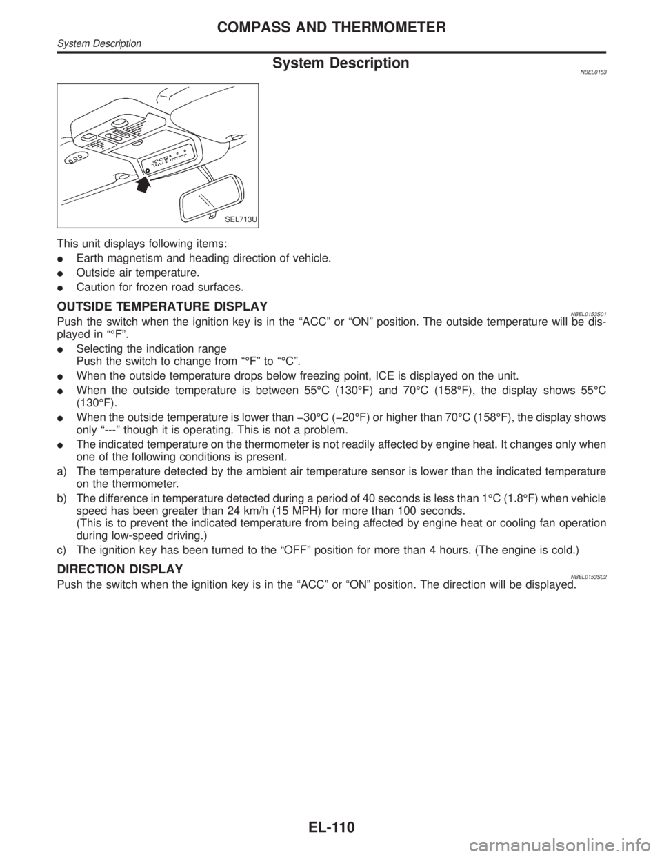
System DescriptionNBEL0153
SEL713U
This unit displays following items:
IEarth magnetism and heading direction of vehicle.
IOutside air temperature.
ICaution for frozen road surfaces.
OUTSIDE TEMPERATURE DISPLAYNBEL0153S01Push the switch when the ignition key is in the ªACCº or ªONº position. The outside temperature will be dis-
played in ªÉFº.
ISelecting the indication range
Push the switch to change from ªÉFº to ªÉCº.
IWhen the outside temperature drops below freezing point, ICE is displayed on the unit.
IWhen the outside temperature is between 55ÉC (130ÉF) and 70ÉC (158ÉF), the display shows 55ÉC
(130ÉF).
IWhen the outside temperature is lower than þ30ÉC (þ20ÉF) or higher than 70ÉC (158ÉF), the display shows
only ª---º though it is operating. This is not a problem.
IThe indicated temperature on the thermometer is not readily affected by engine heat. It changes only when
one of the following conditions is present.
a) The temperature detected by the ambient air temperature sensor is lower than the indicated temperature
on the thermometer.
b) The difference in temperature detected during a period of 40 seconds is less than 1ÉC (1.8ÉF) when vehicle
speed has been greater than 24 km/h (15 MPH) for more than 100 seconds.
(This is to prevent the indicated temperature from being affected by engine heat or cooling fan operation
during low-speed driving.)
c) The ignition key has been turned to the ªOFFº position for more than 4 hours. (The engine is cold.)
DIRECTION DISPLAYNBEL0153S02Push the switch when the ignition key is in the ªACCº or ªONº position. The direction will be displayed.
COMPASS AND THERMOMETER
System Description
EL-110
Page 1297 of 2395
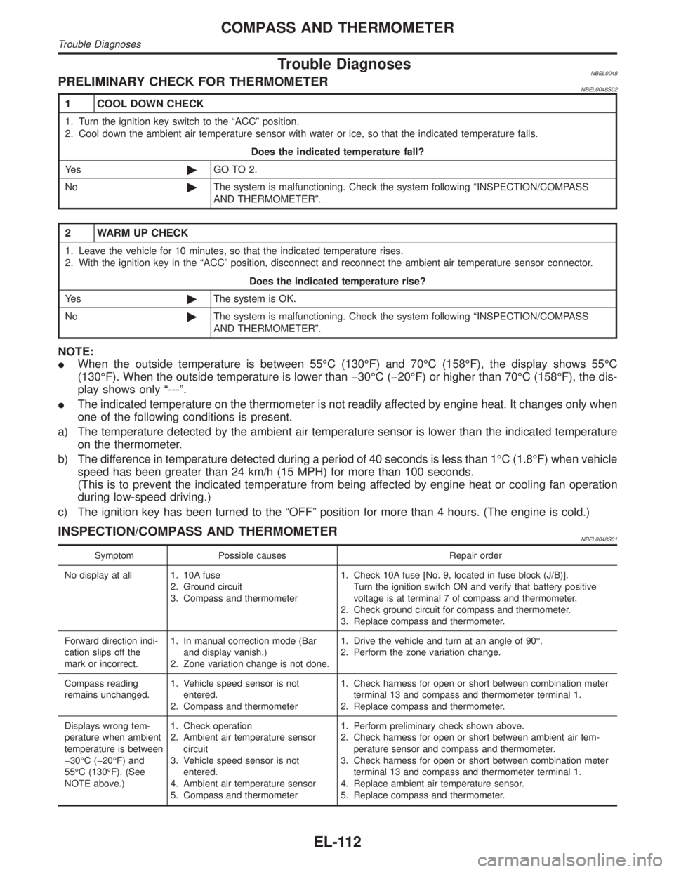
Trouble DiagnosesNBEL0048PRELIMINARY CHECK FOR THERMOMETERNBEL0048S02
1 COOL DOWN CHECK
1. Turn the ignition key switch to the ªACCº position.
2. Cool down the ambient air temperature sensor with water or ice, so that the indicated temperature falls.
Does the indicated temperature fall?
Ye s©GO TO 2.
No©The system is malfunctioning. Check the system following ªINSPECTION/COMPASS
AND THERMOMETERº.
2 WARM UP CHECK
1. Leave the vehicle for 10 minutes, so that the indicated temperature rises.
2. With the ignition key in the ªACCº position, disconnect and reconnect the ambient air temperature sensor connector.
Does the indicated temperature rise?
Ye s©The system is OK.
No©The system is malfunctioning. Check the system following ªINSPECTION/COMPASS
AND THERMOMETERº.
NOTE:
IWhen the outside temperature is between 55ÉC (130ÉF) and 70ÉC (158ÉF), the display shows 55ÉC
(130ÉF). When the outside temperature is lower than þ30ÉC (þ20ÉF) or higher than 70ÉC (158ÉF), the dis-
play shows only ª---º.
IThe indicated temperature on the thermometer is not readily affected by engine heat. It changes only when
one of the following conditions is present.
a) The temperature detected by the ambient air temperature sensor is lower than the indicated temperature
on the thermometer.
b) The difference in temperature detected during a period of 40 seconds is less than 1ÉC (1.8ÉF) when vehicle
speed has been greater than 24 km/h (15 MPH) for more than 100 seconds.
(This is to prevent the indicated temperature from being affected by engine heat or cooling fan operation
during low-speed driving.)
c) The ignition key has been turned to the ªOFFº position for more than 4 hours. (The engine is cold.)
INSPECTION/COMPASS AND THERMOMETERNBEL0048S01
Symptom Possible causes Repair order
No display at all 1. 10A fuse
2. Ground circuit
3. Compass and thermometer1. Check 10A fuse [No. 9, located in fuse block (J/B)].
Turn the ignition switch ON and verify that battery positive
voltage is at terminal 7 of compass and thermometer.
2. Check ground circuit for compass and thermometer.
3. Replace compass and thermometer.
Forward direction indi-
cation slips off the
mark or incorrect.1. In manual correction mode (Bar
and display vanish.)
2. Zone variation change is not done.1. Drive the vehicle and turn at an angle of 90É.
2. Perform the zone variation change.
Compass reading
remains unchanged.1. Vehicle speed sensor is not
entered.
2. Compass and thermometer1. Check harness for open or short between combination meter
terminal 13 and compass and thermometer terminal 1.
2. Replace compass and thermometer.
Displays wrong tem-
perature when ambient
temperature is between
þ30ÉC (þ20ÉF) and
55ÉC (130ÉF). (See
NOTE above.)1. Check operation
2. Ambient air temperature sensor
circuit
3. Vehicle speed sensor is not
entered.
4. Ambient air temperature sensor
5. Compass and thermometer1. Perform preliminary check shown above.
2. Check harness for open or short between ambient air tem-
perature sensor and compass and thermometer.
3. Check harness for open or short between combination meter
terminal 13 and compass and thermometer terminal 1.
4. Replace ambient air temperature sensor.
5. Replace compass and thermometer.
COMPASS AND THERMOMETER
Trouble Diagnoses
EL-112
Page 1330 of 2395
Trouble DiagnosesNBEL0066REAR WIPER AMP. INSPECTION TABLENBEL0066S01(Data are reference values.)
Terminal No. Item Condition Voltage
(Approximate value)
1 Washer switch
Rear wiper switch WASH Less than 1V
OFF, ON or INT Battery voltage
2 Low switch
Rear wiper switch ON Less than 1V
OFF or INT Battery voltage
3 Glass hatch switch
Glass hatch Open Less than 1V
Closed Battery voltage
4 Intermittent switch
Rear wiper switch INT Less than 1V
OFF, ON or WASH Battery voltage
6 Power supply (ACC)
Ð Battery voltage
7 Washer motor
Rear washer switch WASH Battery voltage
OFF, ON or INT Less than 1V
8 Rear wiper motor
Wiper is moving (except final drive) Less than 1V
Wiper stop Less than 1V
During wiper final drive Battery voltage
9 Ground Ð Ð
10 Auto stop switch
Rear wiper switch
should be at ªINTº to
inspect the value for
wiper movement.Wiper is moving Less than 1V
Wiper stop Battery voltage
11 Rear wiper motor
Wiper is moving (except final drive) Battery voltage
Wiper stop Battery voltage
During wiper final drive Less than 1V
NOTE:
Power to the rear wiper amp. will be interrupted when the rear glass hatch is opened. In that case, conduct
the inspection of the rear wiper amp. with the rear glass hatch closed, unless otherwise indicated.
MEL066G
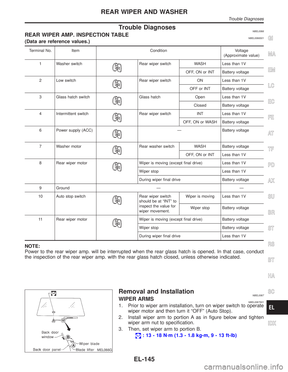
Removal and InstallationNBEL0067WIPER ARMSNBEL0067S011. Prior to wiper arm installation, turn on wiper switch to operate
wiper motor and then turn it ªOFFº (Auto Stop).
2. Install wiper arm to portion A as in figure below and tighten
wiper arm nut to specification.
3. Then, set wiper arm to portion B.
: 13 - 18 N´m (1.3 - 1.8 kg-m,9-13ft-lb)
GI
MA
EM
LC
EC
FE
AT
TF
PD
AX
SU
BR
ST
RS
BT
HA
SC
IDX
REAR WIPER AND WASHER
Trouble Diagnoses
EL-145
Page 1372 of 2395
System Description=NBEL0210OPERATIVE CONDITIONNBEL0210S01The drive position can be set in 2 ways, manually and automatically.
Manual OperationNBEL0210S0101The driver's seat can be adjusted for sliding, reclining, front cushion height and rear cushion height with the
LH power seat switches. The manual operation can be adjusted with the IGN key in any position.
Automatic OperationNBEL0210S0102The driver's seat is adjusted to the proper positions for the driver automatically, in 3 different ways: MEMORY
AUTOMATIC SET, AUTOMATIC EXITING SETTING and AUTOMATIC SET RETURN. (Automatic Drive Posi-
tioner = ADP)
CONDITIONS INHIBITING AUTOMATIC OPERATIONNBEL0210S02Automatic memory setting procedures are suspended under any of the following conditions:
1) When vehicle speed is more than 7 km/h (4 MPH).
2) When driver's side power seat switch is turned on.
3) When any two of the switches (set switch and memory switches 1 and 2) are turned ON.
4) When cancel switch is turned on.
5) When selector lever is in any position other than ªPº.
6) When ignition switch is turned to ªSTARTº position.
(Operation resumes when ignition switch is returned to ªONº.)
7) When detention switch malfunction is detected:
IDetention switch failure is sensed when detention switch remains off for at least 2 seconds at a vehicle
speed of greater than 7 km/h (4 MPH).
FAIL-SAFE SYSTEMNBEL0210S03Output FailureNBEL0210S0301When the ignition switch is in the ON position, if any of the parts (indicated in the following chart) move more
than the specified amount within a period ªT2º when no ªONº input is sent from any of the switches (indicated
in the following chart), or an output from the automatic drive positioner is not produced, an output failure is
sensed. Motor operation will be suspended automatically, and all automatic operations will be ineffective. (In
this case, the motor will not operate manually.)
OPERATED PORTION T2 Allowable measurement
Seat sliding Approx. 2.5 sec. Within 6 mm (0.24 in)
Seat reclining Same as above Change angle within 1É
AbsolvingNBEL0210S0302When moving selector lever back to ªPº position after having moved it to any position except ªPº, fail-safe
operation will be canceled.
INITIALIZATIONNBEL0210S04After reconnecting battery cable, perform initialization procedure A or B. If initialization has not been performed,
automatic drive positioner will not operate.
PROCEDURE A
1) Insert key in the ignition key cylinder. (Ignition switch is in ªOFFº position.)
2) Open,close,open driver side door. (Do not perform with the door switch operation.)
3) End
PROCEDURE B
1) Drive the vehicle at more than 25 km/h (16 MPH).
2) End
GI
MA
EM
LC
EC
FE
AT
TF
PD
AX
SU
BR
ST
RS
BT
HA
SC
IDX
AUTOMATIC DRIVE POSITIONER
System Description
EL-187
Page 1407 of 2395
System DescriptionNBEL0216Refer to Owner's Manual for ASCD operating instructions.
POWER SUPPLY AND GROUNDNBEL0216S01Power is supplied at all times:
Ithrough 10A fuse [No. 14, located in the fuse block (J/B)]
Ito the stop lamp switch terminal 1, and
Ithrough 7.5A fuse (No. 52, located in fuse and fusible link box)
Ito the horn relay terminals 1 and 3.
When ignition switch is in the ON or START position, power is supplied:
Ithrough 7.5A fuse [No. 11, located in the fuse block (J/B)]
Ito ASCD brake switch terminal 1 and
Ito ASCD control unit terminal 5,
Ithrough 10A fuse [No. 18, located in the fuse block (J/B)]
Ito park/neutral position relay terminal 1,
Ithrough 10A fuse [No. 8, located in the fuse block (J/B)]
Ito combination meter terminal 66, and
When park/neutral position switch is in the P or N position, ground is supplied:
Ito park/neutral position relay terminal 2
Ithrough park/neutral position switch and body grounds B55 and B75.
When ASCD main switch is depressed (ON), ground is supplied:
Ito ASCD control unit terminal 9
Ifrom ASCD steering switch terminal 4
Ito ASCD steering switch terminal 5
Ithrough body grounds M4, M66 and M147
then ASCD control unit holds CRUISE condition and illuminates CRUISE indicator.
Ground is supplied:
Ifrom ASCD control unit terminal 15
Ito combination meter terminal 46.
OPERATIONNBEL0216S02Set OperationNBEL0216S0201To activate the ASCD, all following conditions must exist.
IGround supply to ASCD control unit terminal 9 (Main switch is in ON position.)
IPower supply to ASCD control unit terminal 8 (Brake pedal is released and A/T selector lever is in other
than P and N position.)
IVehicle speed is between 40 km/h (25 MPH) and 144 km/h (89 MPH). (Signal from combination meter)
When the SET/COAST switch is depressed, power is supplied:
Ifrom ASCD steering switch terminal 2
Ito ASCD control unit terminal 11.
And then ASCD pump is activated to control throttle wire and ASCD control unit supply ground
Ito combination meter terminals 51 to illuminate SET indicator.
A/T Overdrive Control during Cruise Control DrivingNBEL0216S0202When the vehicle speed is approximately 3 km/h (2 MPH) below set speed, a signal is sent
Ifrom ASCD control unit terminal 10
Ito TCM (transmission control module) terminal 24.
When this occurs, the TCM (transmission control module) cancels overdrive.
After vehicle speed is approximately 1 km/h (1 MPH) below set speed, overdrive is reactivated.
ASCD Shifting ControlNBEL0216S0203During ASCD cruise, ASCD control unit controls A/T shifting to avoid uncomfortable shifting.
This is used to control the signals below.
IThrottle position sensor from ECM
AUTOMATIC SPEED CONTROL DEVICE (ASCD)
System Description
EL-222