Page 1658 of 2395
ComponentsNBEM0008
SEM583G
RemovalNBEM0009WARNING:
IPlace vehicle on a flat and solid surface.
IYou should not remove oil pan until exhaust system and
cooling system have completely cooled off.
Otherwise, you may burn yourself and/or fire may break
out in the fuel line.
IWhen removing front engine mounting nuts, lift up slightly
engine for safety work.
CAUTION:
When removing the aluminum oil pan from engine, first
remove the crankshaft position sensors (POS and REF) from
the assembly.
Be careful not to damage sensor edges and signal plate teeth.
1. Remove front RH and LH wheels.
2. Remove battery.
3. Remove oil level gauge.
4. Remove engine undercover.
5. Remove suspension member stay.
6. Drain engine coolant from radiator drain plug.
7. Disconnect A/T oil cooler hoses.
8. Drain engine oil.
GI
MA
LC
EC
FE
AT
TF
PD
AX
SU
BR
ST
RS
BT
HA
SC
EL
IDX
OIL PAN
Components
EM-15
Page 1666 of 2395
CAUTION:
IAfter removing timing chain, do not turn crankshaft and
camshaft separately, or valves will strike piston heads.
IWhen installing camshafts, chain tensioners, oil seals, or
other sliding parts, lubricate contacting surfaces with new
engine oil.
IApply new engine oil to bolt threads and seat surfaces
when installing camshaft sprockets and crankshaft pulley.
IBefore disconnecting fuel hose, release fuel pressure.
Refer to EC-39, ªFuel Pressure Releaseº.
IBe careful not to damage sensor edges.
IDo not spill engine coolant on drive belts.
RemovalNBEM00121. Release fuel pressure.
Refer to EC-39, ªFuel Pressure Releaseº.
2. Remove battery.
3. Remove radiator.
Refer to LC-19, ªREMOVAL AND INSTALLATIONº.
4. Drain engine oil.
5. Remove drive belts and idler pulley with brackets.
6. Remove cooling fan with bracket.
7. Remove engine cover.
8. Remove air duct with air cleaner case, collector, blow-by hose,
vacuum hoses, fuel hoses, water hoses, wires, harnesses,
connectors and so on.
9. Remove the air compressor, and tie it down using rope or the
like to keep it from interfering.
10. Remove the power steering oil pump and reservoir tank. Tie
them down using rope or the like to keep them from interfer-
ing.
11. Remove alternator.
12. Remove the following.
IVacuum gallery
IWater bypass pipe
IBrackets
GI
MA
LC
EC
FE
AT
TF
PD
AX
SU
BR
ST
RS
BT
HA
SC
EL
IDX
TIMING CHAIN
Components (Cont'd)
EM-23
Page 1678 of 2395
SEM948E
ReplacementNBEM0015CAUTION:
When removing the oil pans, oil pump assembly and timing
chain from engine, first remove the camshaft position sensor
(PHASE), CVTC sensor and the crankshaft position sensors
(REF)/(POS) from the assembly.
Be careful not to damage sensor edges.
VALVE OIL SEALNBEM0015S011. Remove timing chain. Refer to ªRemoval, EM-23.
2. Remove camshaft brackets and camshaft. Refer to
ªDisassemblyº, EM-41.
3. Remove valve lifters and shims.
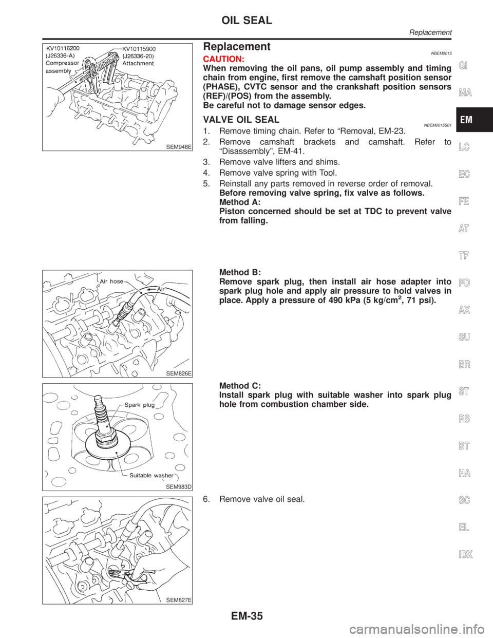
4. Remove valve spring with Tool.
5. Reinstall any parts removed in reverse order of removal.
Before removing valve spring, fix valve as follows.
Method A:
Piston concerned should be set at TDC to prevent valve
from falling.
SEM826E
Method B:
Remove spark plug, then install air hose adapter into
spark plug hole and apply air pressure to hold valves in
place. Apply a pressure of 490 kPa (5 kg/cm
2, 71 psi).
SEM983D
Method C:
Install spark plug with suitable washer into spark plug
hole from combustion chamber side.
SEM827E
6. Remove valve oil seal.
GI
MA
LC
EC
FE
AT
TF
PD
AX
SU
BR
ST
RS
BT
HA
SC
EL
IDX
OIL SEAL
Replacement
EM-35
Page 1684 of 2395
SEM444G
14. Remove RH and LH camshaft chain tensioners from cylinder
head.
SEM859E
SEM860E
15. Remove cylinder head bolts.
ICylinder head bolts should be loosened in two or three
steps.
IA warped or cracked cylinder head could result from
removing in incorrect order.
SEM863E
16. Remove cylinder head.
DisassemblyNBEM0043Remove valve component parts.
Refer to EM-35, ªVALVE OIL SEALº.
ICheck the clearance before removing the valve guide. Refer to
EM-43, ªVALVE GUIDE CLEARANCEº.
GI
MA
LC
EC
FE
AT
TF
PD
AX
SU
BR
ST
RS
BT
HA
SC
EL
IDX
CYLINDER HEAD
Removal (Cont'd)
EM-41
Page 1700 of 2395
Removal and InstallationNBEM0042WARNING:
ISituate vehicle on a flat and solid surface.
IPlace chocks at front and back of rear wheels.
IDo not remove engine until exhaust system has com-
pletely cooled off. Otherwise, you may burn yourself
and/or fire may break out in fuel line.
IFor safety during subsequent steps, the tension of wires
should be slackened against the engine.
IBefore disconnecting fuel hose, release fuel pressure
from fuel line.
Refer to EC-39, ªFuel Pressure Releaseº.
IBefore removing front axle from transmission, place
safety stands under designated front supporting points.
Refer to GI section for lifting points and towing.
IBe sure to hoist engine and transmission in a safe man-
ner.
IFor engines not equipped with engine slingers, attach
proper slingers and bolts described in PARTS CATALOG.
CAUTION:
IWhen lifting engine, be careful not to strike adjacent parts,
especially accelerator wire casing, brake lines, and brake
master cylinder.
IIn hoisting the engine, always use engine slingers in a
safe manner.
IBefore separating engine and transmission, remove
crankshaft position sensor (POS) from the assembly.
IAlways take extra care not to damage edge of crankshaft
position sensor (POS), or ring gear teeth.GI
MA
LC
EC
FE
AT
TF
PD
AX
SU
BR
ST
RS
BT
HA
SC
EL
IDX
ENGINE ASSEMBLY
Removal and Installation
EM-57
Page 1706 of 2395
SEM965A
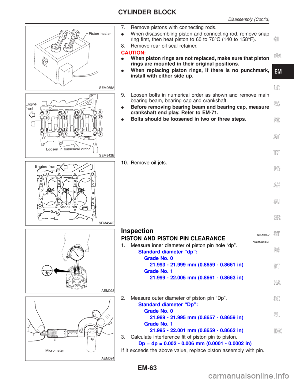
7. Remove pistons with connecting rods.
IWhen disassembling piston and connecting rod, remove snap
ring first, then heat piston to 60 to 70ÉC (140 to 158ÉF).
8. Remove rear oil seal retainer.
CAUTION:
IWhen piston rings are not replaced, make sure that piston
rings are mounted in their original positions.
IWhen replacing piston rings, if there is no punchmark,
install with either side up.
SEM842E
9. Loosen bolts in numerical order as shown and remove main
bearing beam, bearing cap and crankshaft.
IBefore removing bearing beam and bearing cap, measure
crankshaft end play. Refer to EM-71.
IBolts should be loosened in two or three steps.
SEM454G
10. Remove oil jets.
AEM023
InspectionNBEM0027PISTON AND PISTON PIN CLEARANCENBEM0027S011. Measure inner diameter of piston pin hole ªdpº.
Standard diameter ªdpº:
Grade No. 0
21.993 - 21.999 mm (0.8659 - 0.8661 in)
Grade No. 1
21.999 - 22.005 mm (0.8661 - 0.8663 in)
AEM024
2. Measure outer diameter of piston pin ªDpº.
Standard diameter ªDpº:
Grade No. 0
21.989 - 21.995 mm (0.8657 - 0.8659 in)
Grade No. 1
21.995 - 22.001 mm (0.8659 - 0.8662 in)
3. Calculate interference fit of piston pin to piston.
Dp þ dp = 0.002 - 0.006 mm (0.0001 - 0.0002 in)
If it exceeds the above value, replace piston assembly with pin.
GI
MA
LC
EC
FE
AT
TF
PD
AX
SU
BR
ST
RS
BT
HA
SC
EL
IDX
CYLINDER BLOCK
Disassembly (Cont'd)
EM-63
Page 1732 of 2395
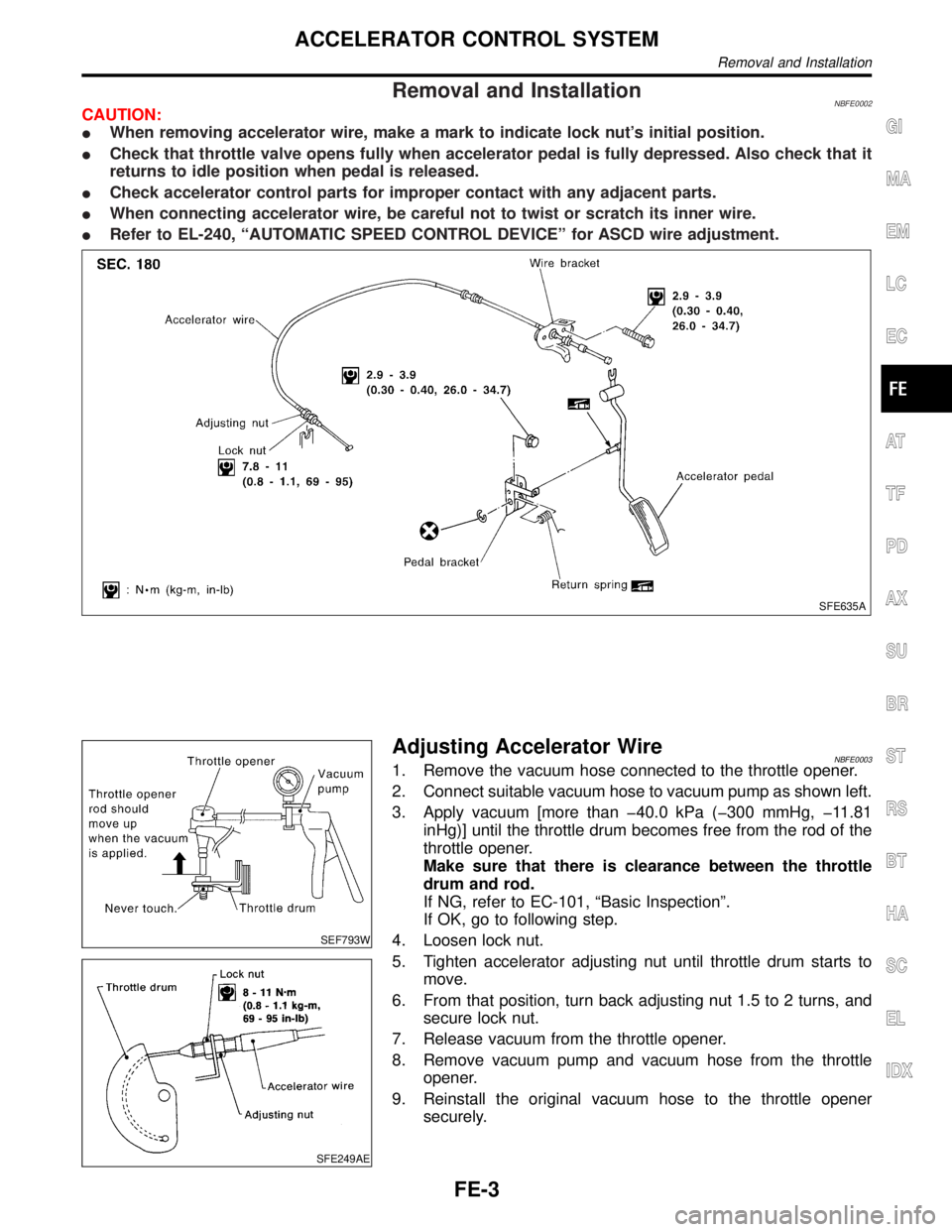
Removal and InstallationNBFE0002CAUTION:
IWhen removing accelerator wire, make a mark to indicate lock nut's initial position.
ICheck that throttle valve opens fully when accelerator pedal is fully depressed. Also check that it
returns to idle position when pedal is released.
ICheck accelerator control parts for improper contact with any adjacent parts.
IWhen connecting accelerator wire, be careful not to twist or scratch its inner wire.
IRefer to EL-240, ªAUTOMATIC SPEED CONTROL DEVICEº for ASCD wire adjustment.
SFE635A
SEF793W
SFE249AE
Adjusting Accelerator WireNBFE00031. Remove the vacuum hose connected to the throttle opener.
2. Connect suitable vacuum hose to vacuum pump as shown left.
3. Apply vacuum [more than þ40.0 kPa (þ300 mmHg, þ11.81
inHg)] until the throttle drum becomes free from the rod of the
throttle opener.
Make sure that there is clearance between the throttle
drum and rod.
If NG, refer to EC-101, ªBasic Inspectionº.
If OK, go to following step.
4. Loosen lock nut.
5. Tighten accelerator adjusting nut until throttle drum starts to
move.
6. From that position, turn back adjusting nut 1.5 to 2 turns, and
secure lock nut.
7. Release vacuum from the throttle opener.
8. Remove vacuum pump and vacuum hose from the throttle
opener.
9. Reinstall the original vacuum hose to the throttle opener
securely.
GI
MA
EM
LC
EC
AT
TF
PD
AX
SU
BR
ST
RS
BT
HA
SC
EL
IDX
ACCELERATOR CONTROL SYSTEM
Removal and Installation
FE-3
Page 1733 of 2395
Removal and InstallationNBFE0004WARNING:
When replacing fuel line parts, be sure to observe the follow-
ing:
IPut a ªCAUTION: INFLAMMABLEº sign in workshop.
IDo not smoke while servicing fuel system. Keep open
flames and sparks away from work area.
IBe sure to furnish the workshop with a CO
2fire extin-
guisher.
CAUTION:
IBefore removing fuel line parts, carry out the following
procedures:
a) Put drained fuel in an explosion-proof container and put
lid on securely.
b) Release fuel pressure from fuel line. Refer to MA-16,
ªChanging Fuel Filterº.
c) Disconnect battery ground cable.
IAlways replace O-ring with new ones.
IDo not kink or twist hose and tube when they are installed.
IDo not tighten hose clamps excessively to avoid damag-
ing hoses.
IWhen installing fuel check valve, be careful of its desig-
nated direction. Refer to EC-32, ªEVAPORATIVE EMIS-
SION SYSTEMº.
IAfter installation, run engine and check for fuel leaks at
connections.
FUEL SYSTEM
Removal and Installation
FE-4