2001 INFINITI QX4 vin
[x] Cancel search: vinPage 1614 of 2395
GPS signal reception conditions are good. However, the position mark does not return to its proper
position.
Ihe system senses the vehicle location with an error of approximately 100 m (328 ft). Due to the limitation
of precision, the position marker may be inaccurate even if the GPS signal reception condition is good.
IThe navigation system uses GPS data to determine vehicle location. GPS data is compared with other
locational sensing data during the map matching process. The system decides which data is more pre-
cise and uses that data.
IWhen the vehicle is stationary, GPS data cannot be used to make system corrections.
Area designations on the map display and the BIRDVIEWTdisplay differ.
To prevent the display from becoming congested, alphanumeric information is abridged.
[No problem]
Correct position of your vehicle is not displayed.
Vehicle position changed after ignition key was turned to the OFF position (Vehicle is transported on car ferry,
car train, or by some other means).
[Operate vehicle for short time under GPS receiving conditions.]
The display does not change to night-time mode even though the light switch has been turned ON.
Lights have been turned on. In ªDISPLAY CHANGEº mode, night-time mode on display has been switched to
day-time mode and still is.
[Turn lights on again. Set the display to night-time mode. Refer to EL-412.]
Map does not scroll even though the position of your vehicle is changed.
Present area does not appear on the display.
[Press the ªMAPº switch.]
Vehicle position marker does not appear.
Present area does not appear on the display.
[Press the ªMAPº switch.]
The map surface precision display (GPS satellite marker) still remains gray.
Vehicle is parked inside a building or in the shadow of a large building. This intercepts the GPS signal.
[Move the vehicle to a more open position.]
GPS signal is not received because objects are placed on the rear parcel shelf.
[Remove objects from the rear parcel shelf.]
GPS satellite position is bad.
[Wait until GPS satellite position improves.]
Vehicle position precision is bad.
The map surface precision display (GPS satellite marker) still remains gray.
[Refer to ªThe map surface precision display (GPS satellite marker) still remains grayº item (Symptoms)]
Vehicle speed and elapsed distance is calculated from the vehicle speed pulse. This pulse is dependent upon
tire size. If tire chains are used on the vehicle, accuracy will be affected (pulse rate will be too fast or too slow).
The same is true if the system installed to your vehicle is removed and installed on another vehicle.
[Drive the vehicle at a speed higher than 30 km/h (19 MPH) for approximately 30 minutes. Automatic read-
justment should occur. If it does not (remains too fast or too slow), distance calibration is required. Or, drive
the vehicle for a short distance. Perform ªSPEED CALIBRATIONº (EL-409). After removing the tire chains,
sensing accuracy may recover by itself.]
Bad map data or system defect (same error consistently occurs in the same area)
ROUTE SEARCH/ROUTE GUIDENBEL0235S03IIf the present location or the destination location is displayed in the avoid area, it is not possible to search
routes.
IIf the avoid area is set to wide range area, it may not be possible to find appropriate routes or search for
alternate routes.
IThe automatic re-route calculates a return to the original route. Because of this, it may not be possible to
search appropriate new routes. If you deviate from the original route and wish to select an appropriate new
route, touch ªRoute Calculationº.
IThe automatic re-route function may sometimes require considerable time.
IDisplayed route number and directional information at a highway junction may differ from the information
posted on the actual road signs.
IDisplayed street name information at a highway exit may differ from the information posted on the actual
road signs.
IStreet name information displayed on the enlarged intersection map may differ from the information posted
on the actual road signs.
GI
MA
EM
LC
EC
FE
AT
TF
PD
AX
SU
BR
ST
RS
BT
HA
SC
IDX
NAVIGATION SYSTEM
This Condition is Not Abnormal (Cont'd)
EL-429
Page 1616 of 2395
Symptom Possible cause Repair order
No route is displayed.No object route is searched near destination
area.Adjust position to wide road (brown) near des-
tination area. In an area where traffic direction
is displayed separately, pay close attention to
the direction of travel. Set the destination area
and the way point over the road.
Starting point and destination areas are very
near.Move destination areas away from starting
point on the screen.
Recommended route which has
been passed disappears from the
display.The recommended route is divided into indi-
vidual control segments. When way point 1 is
passed, the data from the starting point to the
way point 1 is erased.This is not abnormal.
Search recommends roundabout
route.There may be special conditions for roads
near the starting point and destination area
(one-way traffic, etc.). A roundabout route may
be displayed.Slightly change starting point and destination
area settings.
Landmark display does not show
actual conditions.Mistaken or missing map data may result in
erroneous display.Change map CD.
Recommended route drawn
slightly away from starting point,
way points, and destination area.Course search data may not exist for closely
positioned starting point, way points, and des-
tination area shown on the map. Route guide
starting point, way point, and destination point
may be separated.Set the destination area to the general route
(indicated by a thick brown line). However,
even if the selected route is a major one,
appropriate route search data may not be
available.
LOCATION OF CAR MARKERNBEL0235S04IIf the vehicle has been parked in a multi-level parking facility or underground parking facility, the car marker
position may be inaccurate immediately after exiting the parking facility.
IThe GPS accuracy is within±100 m (300 ft). Even when receiving conditions are excellent, further posi-
tional correction may not occur.
STREET INDICATIONNBEL0235S05IStreet names displayed on the map may differ from the actual street names.
IAn ªUnknown Streetº message may appear on the map in place of street name information.
RESEARCHNBEL0235S06IPosition may be searched by house number. However, the displayed position and street may differ from
the actual position and street.
IWhen position is searched using POI, the displayed position may differ from the actual position.
ISome data may not be available for new buildings and other structures in a map.
GPS ANTENNANBEL0235S07IDo not place metal objects above the GPS antenna mounted on the rear parcel shelf. This will cause
interference with signal reception.
IDo not place mobile telephones or vehicle radio transceivers in close proximity to the GPS antenna
mounted on the rear parcel shelf. This may cause interference with signal reception.
GI
MA
EM
LC
EC
FE
AT
TF
PD
AX
SU
BR
ST
RS
BT
HA
SC
IDX
NAVIGATION SYSTEM
This Condition is Not Abnormal (Cont'd)
EL-431
Page 1618 of 2395
InitializationNBEL0237This procedure is for initializing the current location. Perform ªIni-
tialize Locationº when the vehicle is transported a long distance by
trailer, etc.
Map with grey background appears and the vehicle location can-
not be adjusted by scrolling the display when the vehicle location
in the memory is out of the area of the inserted map data.
Perform ªInitialize Locationº when this occurs.
NOTE:
IOnly initialize the system when the display & NAVI control
unit is replaced. If the system is initialized in other cases,
it may cause inaccurate positioning of the position marker
for a while.
IInitialize the system outside for receiving the radio wave
from the GPS satellite.
SEL583X
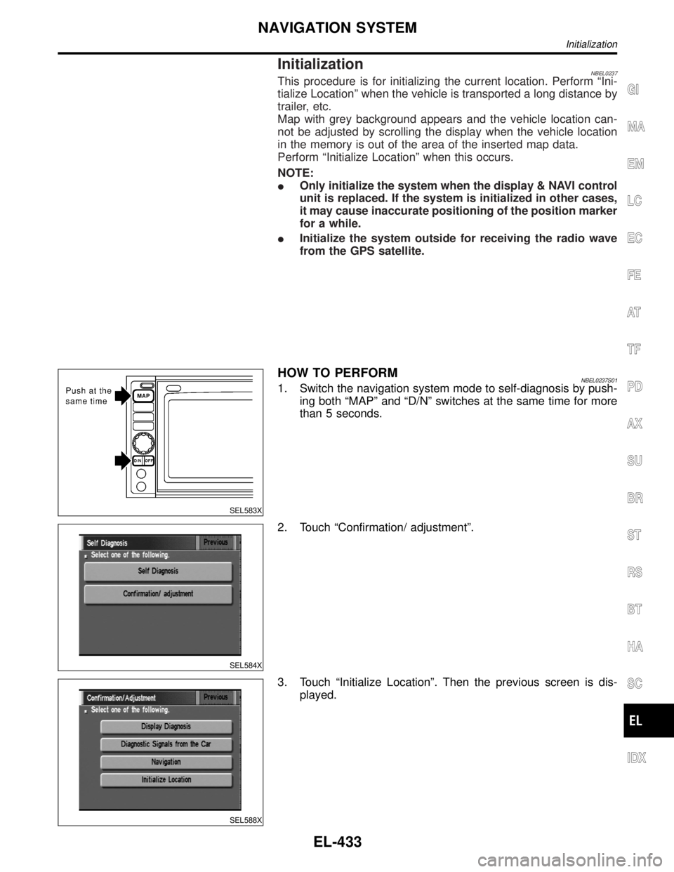
HOW TO PERFORMNBEL0237S011. Switch the navigation system mode to self-diagnosis by push-
ing both ªMAPº and ªD/Nº switches at the same time for more
than 5 seconds.
SEL584X
2. Touch ªConfirmation/ adjustmentº.
SEL588X
3. Touch ªInitialize Locationº. Then the previous screen is dis-
played.
GI
MA
EM
LC
EC
FE
AT
TF
PD
AX
SU
BR
ST
RS
BT
HA
SC
IDX
NAVIGATION SYSTEM
Initialization
EL-433
Page 1619 of 2395
SEL584X
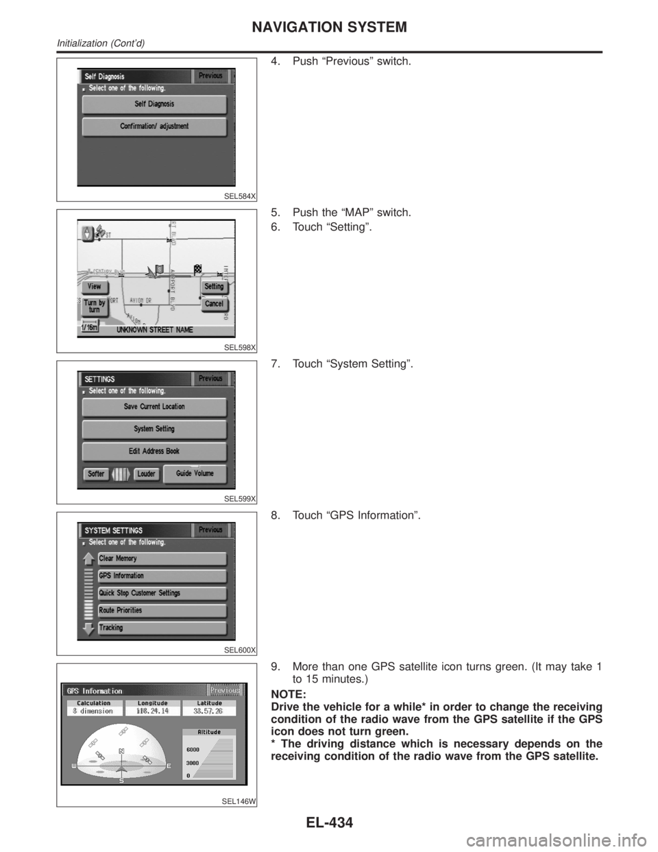
4. Push ªPreviousº switch.
SEL598X
5. Push the ªMAPº switch.
6. Touch ªSettingº.
SEL599X
7. Touch ªSystem Settingº.
SEL600X
8. Touch ªGPS Informationº.
SEL146W
9. More than one GPS satellite icon turns green. (It may take 1
to 15 minutes.)
NOTE:
Drive the vehicle for a while* in order to change the receiving
condition of the radio wave from the GPS satellite if the GPS
icon does not turn green.
* The driving distance which is necessary depends on the
receiving condition of the radio wave from the GPS satellite.
NAVIGATION SYSTEM
Initialization (Cont'd)
EL-434
Page 1648 of 2395
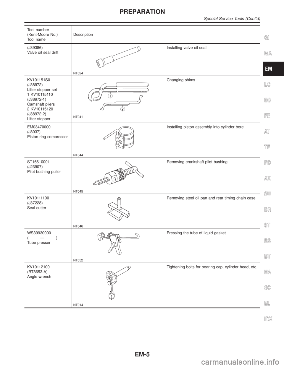
Tool number
(Kent-Moore No.)
Tool nameDescription
(J39386)
Valve oil seal drift
NT024
Installing valve oil seal
KV101151S0
(J38972)
Lifter stopper set
1 KV10115110
(J38972-1)
Camshaft pliers
2 KV10115120
(J38972-2)
Lifter stopper
NT041
Changing shims
EM03470000
(J8037)
Piston ring compressor
NT044
Installing piston assembly into cylinder bore
ST16610001
(J23907)
Pilot bushing puller
NT045
Removing crankshaft pilot bushing
KV101111 0 0
(J37228)
Seal cutter
NT046
Removing steel oil pan and rear timing chain case
WS39930000
(Ð)
Tube presser
NT052
Pressing the tube of liquid gasket
KV10112100
(BT8653-A)
Angle wrench
NT014
Tightening bolts for bearing cap, cylinder head, etc.
GI
MA
LC
EC
FE
AT
TF
PD
AX
SU
BR
ST
RS
BT
HA
SC
EL
IDX
PREPARATION
Special Service Tools (Cont'd)
EM-5
Page 1649 of 2395

Tool number
(Kent-Moore No.)
Tool nameDescription
KV10117100
(J3647-A)
Heated oxygen sensor
wrench
NT379
Loosening or tightening heated oxygen sensor
For 22 mm (0.87 in) hexagon nut
KV10114400
(J38365)
Heated oxygen sensor
wrench
NT636
Loosening or tightening rear heated oxygen sensor
a: 22 mm (0.87 in)
KV10117700
(J44716)
Ring gear stopper
NT822
Removing and installing crankshaft pulley
Commercial Service ToolsNBEM0004
Tool number
(Kent-Moore No.)
Tool nameDescription
Spark plug wrench
NT047
Removing and installing spark plug
Valve seat cutter set
NT048
Finishing valve seat dimensions
Piston ring expander
NT030
Removing and installing piston ring
Valve guide drift
NT015
Removing and installing valve guide
Intake & Exhaust:
a = 9.5 mm (0.374 in) dia.
b = 5.5 mm (0.217 in) dia.
PREPARATION
Special Service Tools (Cont'd)
EM-6
Page 1652 of 2395
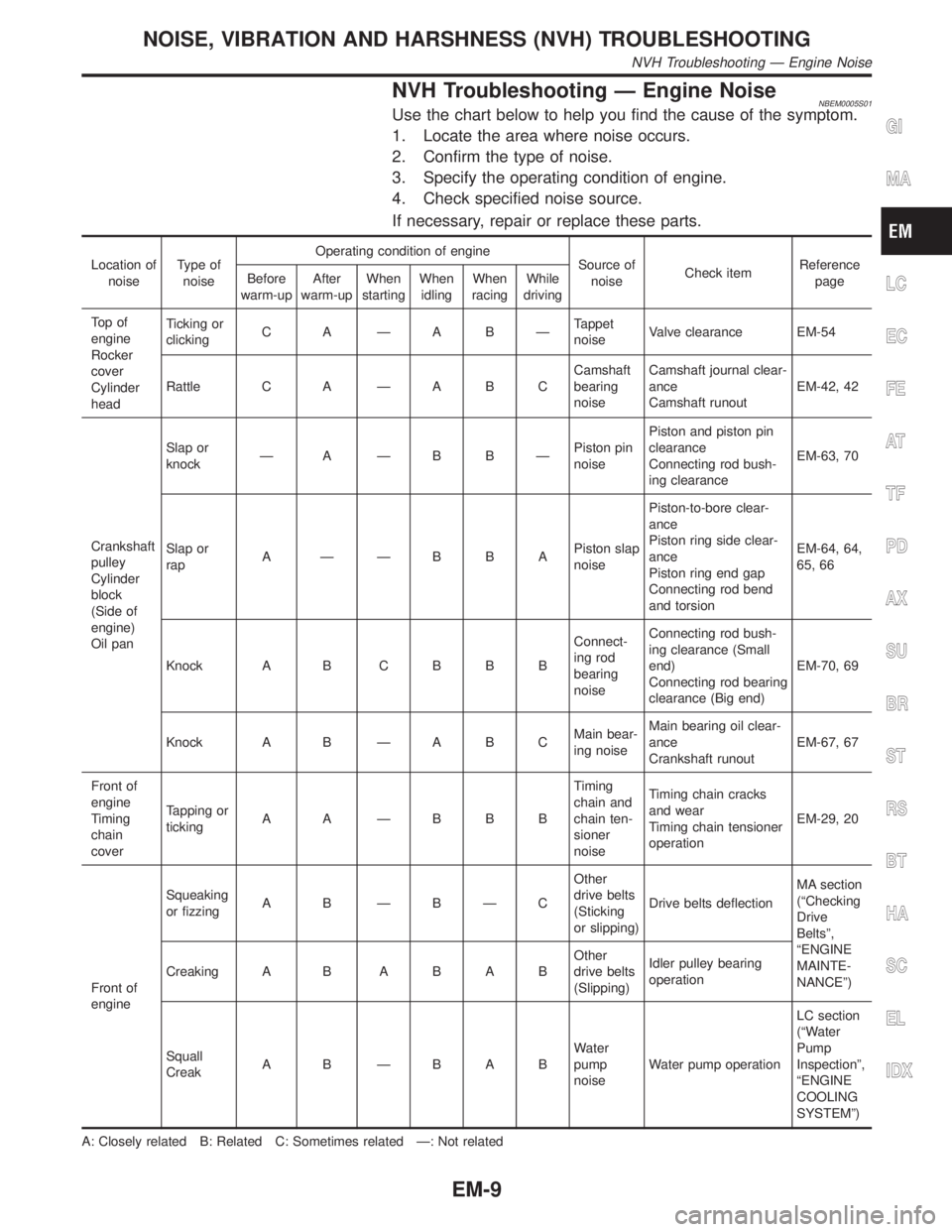
NVH Troubleshooting Ð Engine NoiseNBEM0005S01Use the chart below to help you find the cause of the symptom.
1. Locate the area where noise occurs.
2. Confirm the type of noise.
3. Specify the operating condition of engine.
4. Check specified noise source.
If necessary, repair or replace these parts.
Location of
noiseType of
noiseOperating condition of engine
Source of
noiseCheck itemReference
page Before
warm-upAfter
warm-upWhen
startingWhen
idlingWhen
racingWhile
driving
To p o f
engine
Rocker
cover
Cylinder
headTicking or
clickingC A ÐA BÐTappet
noiseValve clearance EM-54
Rattle C A Ð A B CCamshaft
bearing
noiseCamshaft journal clear-
ance
Camshaft runoutEM-42, 42
Crankshaft
pulley
Cylinder
block
(Side of
engine)
Oil panSlap or
knockÐ A ÐB BÐPiston pin
noisePiston and piston pin
clearance
Connecting rod bush-
ing clearanceEM-63, 70
Slap or
rapA ÐÐBBAPiston slap
noisePiston-to-bore clear-
ance
Piston ring side clear-
ance
Piston ring end gap
Connecting rod bend
and torsionEM-64, 64,
65, 66
Knock A B C B B BConnect-
ing rod
bearing
noiseConnecting rod bush-
ing clearance (Small
end)
Connecting rod bearing
clearance (Big end)EM-70, 69
Knock A B Ð A B CMain bear-
ing noiseMain bearing oil clear-
ance
Crankshaft runoutEM-67, 67
Front of
engine
Timing
chain
coverTapping or
tickingA A ÐBBBTiming
chain and
chain ten-
sioner
noiseTiming chain cracks
and wear
Timing chain tensioner
operationEM-29, 20
Front of
engineSqueaking
or fizzingA B ÐBÐCOther
drive belts
(Sticking
or slipping)Drive belts deflectionMA section
(ªChecking
Drive
Beltsº,
ªENGINE
MAINTE-
NANCEº) Creaking A BABABOther
drive belts
(Slipping)Idler pulley bearing
operation
Squall
CreakA B ÐBABWater
pump
noiseWater pump operationLC section
(ªWater
Pump
Inspectionº,
ªENGINE
COOLING
SYSTEMº)
A: Closely related B: Related C: Sometimes related Ð: Not related
GI
MA
LC
EC
FE
AT
TF
PD
AX
SU
BR
ST
RS
BT
HA
SC
EL
IDX
NOISE, VIBRATION AND HARSHNESS (NVH) TROUBLESHOOTING
NVH Troubleshooting Ð Engine Noise
EM-9
Page 1657 of 2395

NBEM0007
SEM480G
SEM481G
JEM482G
SEM387C
1. Warm up engine.
2. Turn ignition switch OFF.
3. Release fuel pressure.
Refer to EC-39, ªFuel Pressure Releaseº.
4. Remove engine cover and throttle wire.
5. Remove air duct with air cleaner case.
6. Remove harness connectors and harness brackets around
ignition coils.
7. Remove throttle body.
8. Disconnect ignition coil with power transistor harness
connectors, then remove ignition coils.
9. Remove all spark plugs.
IClean area around plug with compressed air before removing
the spark plug.
10. Attach a compression tester to No. 1 cylinder.
11. Depress accelerator pedal fully to keep throttle valve wide
open.
12. Crank engine and record highest gauge indication.
13. Repeat the measurement on each cylinder as shown above.
IAlways use a fully-charged battery to obtain specified
engine speed.
Unit: kPa (kg/cm2, psi)/rpm
Standard MinimumDifference limit between
cylinders
1,275 (13.0, 185)/300 981 (10.0, 142)/300 98 (1.0, 14)/300
14. If compression in one or more cylinders is low:
a. Pour a small amount of engine oil into cylinders through spark
plug holes.
b. Retest compression.
IIf adding oil helps compression, piston rings may be worn
or damaged. If so, replace piston rings after checking pis-
ton.
IIf pressure stays low, a valve may be sticking or seating
improperly. Inspect and repair valve and valve seat. (Refer
to SDS, EM-76 and EM-79.) If valve or valve seat is dam-
aged excessively, replace them.
IIf compression stays low in two cylinders that are next to
each other:
a) The cylinder head gasket may be leaking, or
b) Both cylinders may have valve component damage. Inspect
and repair as necessary.
15. Install parts in reverse order of removal.
16. Perform ªSelf-diagnosis Procedureº referring to EC-72, ªHow to
Erase DTCº if any DTC appears.
MEASUREMENT OF COMPRESSION PRESSURE
EM-14