Page 2013 of 2395
SMA096D
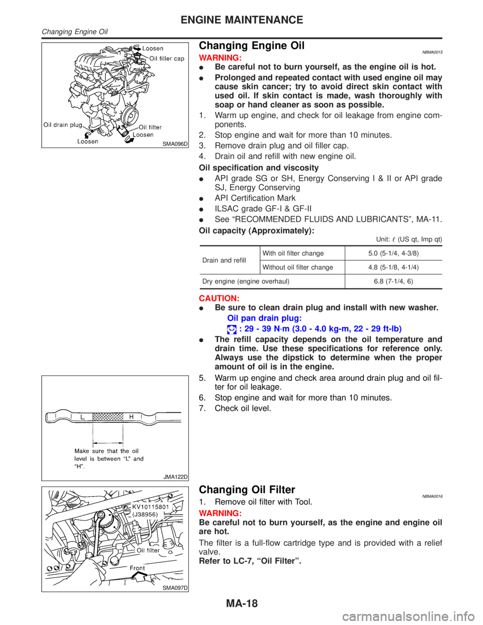
Changing Engine OilNBMA0015WARNING:
IBe careful not to burn yourself, as the engine oil is hot.
IProlonged and repeated contact with used engine oil may
cause skin cancer; try to avoid direct skin contact with
used oil. If skin contact is made, wash thoroughly with
soap or hand cleaner as soon as possible.
1. Warm up engine, and check for oil leakage from engine com-
ponents.
2. Stop engine and wait for more than 10 minutes.
3. Remove drain plug and oil filler cap.
4. Drain oil and refill with new engine oil.
Oil specification and viscosity
IAPI grade SG or SH, Energy ConservingI&IIorAPIgrade
SJ, Energy Conserving
IAPI Certification Mark
IILSAC grade GF-I & GF-II
ISee ªRECOMMENDED FLUIDS AND LUBRICANTSº, MA-11.
Oil capacity (Approximately):
Unit:(US qt, Imp qt)
Drain and refillWith oil filter change 5.0 (5-1/4, 4-3/8)
Without oil filter change 4.8 (5-1/8, 4-1/4)
Dry engine (engine overhaul) 6.8 (7-1/4, 6)
CAUTION:
IBe sure to clean drain plug and install with new washer.
Oil pan drain plug:
: 29 - 39 N´m (3.0 - 4.0 kg-m, 22 - 29 ft-lb)
IThe refill capacity depends on the oil temperature and
drain time. Use these specifications for reference only.
Always use the dipstick to determine when the proper
amount of oil is in the engine.
JMA122D
5. Warm up engine and check area around drain plug and oil fil-
ter for oil leakage.
6. Stop engine and wait for more than 10 minutes.
7. Check oil level.
SMA097D
Changing Oil FilterNBMA00161. Remove oil filter with Tool.
WARNING:
Be careful not to burn yourself, as the engine and engine oil
are hot.
The filter is a full-flow cartridge type and is provided with a relief
valve.
Refer to LC-7, ªOil Filterº.
ENGINE MAINTENANCE
Changing Engine Oil
MA-18
Page 2014 of 2395
SMA010
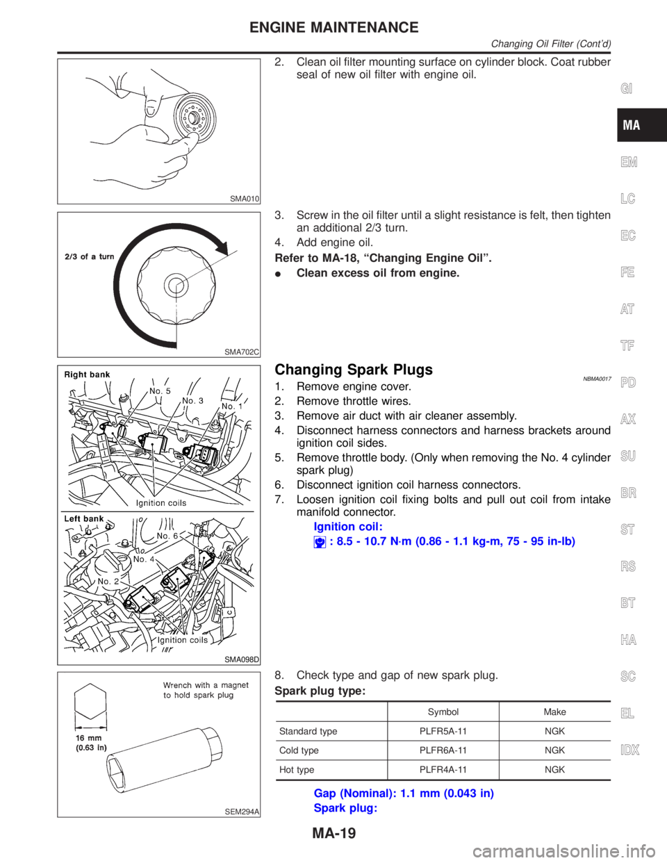
2. Clean oil filter mounting surface on cylinder block. Coat rubber
seal of new oil filter with engine oil.
SMA702C
3. Screw in the oil filter until a slight resistance is felt, then tighten
an additional 2/3 turn.
4. Add engine oil.
Refer to MA-18, ªChanging Engine Oilº.
IClean excess oil from engine.
SMA098D
Changing Spark PlugsNBMA00171. Remove engine cover.
2. Remove throttle wires.
3. Remove air duct with air cleaner assembly.
4. Disconnect harness connectors and harness brackets around
ignition coil sides.
5. Remove throttle body. (Only when removing the No. 4 cylinder
spark plug)
6. Disconnect ignition coil harness connectors.
7. Loosen ignition coil fixing bolts and pull out coil from intake
manifold connector.
Ignition coil:
: 8.5 - 10.7 N´m (0.86 - 1.1 kg-m, 75 - 95 in-lb)
SEM294A
8. Check type and gap of new spark plug.
Spark plug type:
Symbol Make
Standard type PLFR5A-11 NGK
Cold type PLFR6A-11 NGK
Hot type PLFR4A-11 NGK
Gap (Nominal): 1.1 mm (0.043 in)
Spark plug:
GI
EM
LC
EC
FE
AT
TF
PD
AX
SU
BR
ST
RS
BT
HA
SC
EL
IDX
ENGINE MAINTENANCE
Changing Oil Filter (Cont'd)
MA-19
Page 2015 of 2395
: 20 - 29 N´m (2.0 - 3.0 kg-m, 14 - 22 ft-lb)
Use standard type spark plug for normal condition.
The hot type spark plug is suitable when fouling may occur with the
standard type spark plug such as:
Ifrequent engine starts
Ilow ambient temperatures
The cold type spark plug is suitable when spark knock may occur
with the standard type spark plug such as:
Iextended highway driving
Ifrequent high engine revolution
SMA773C
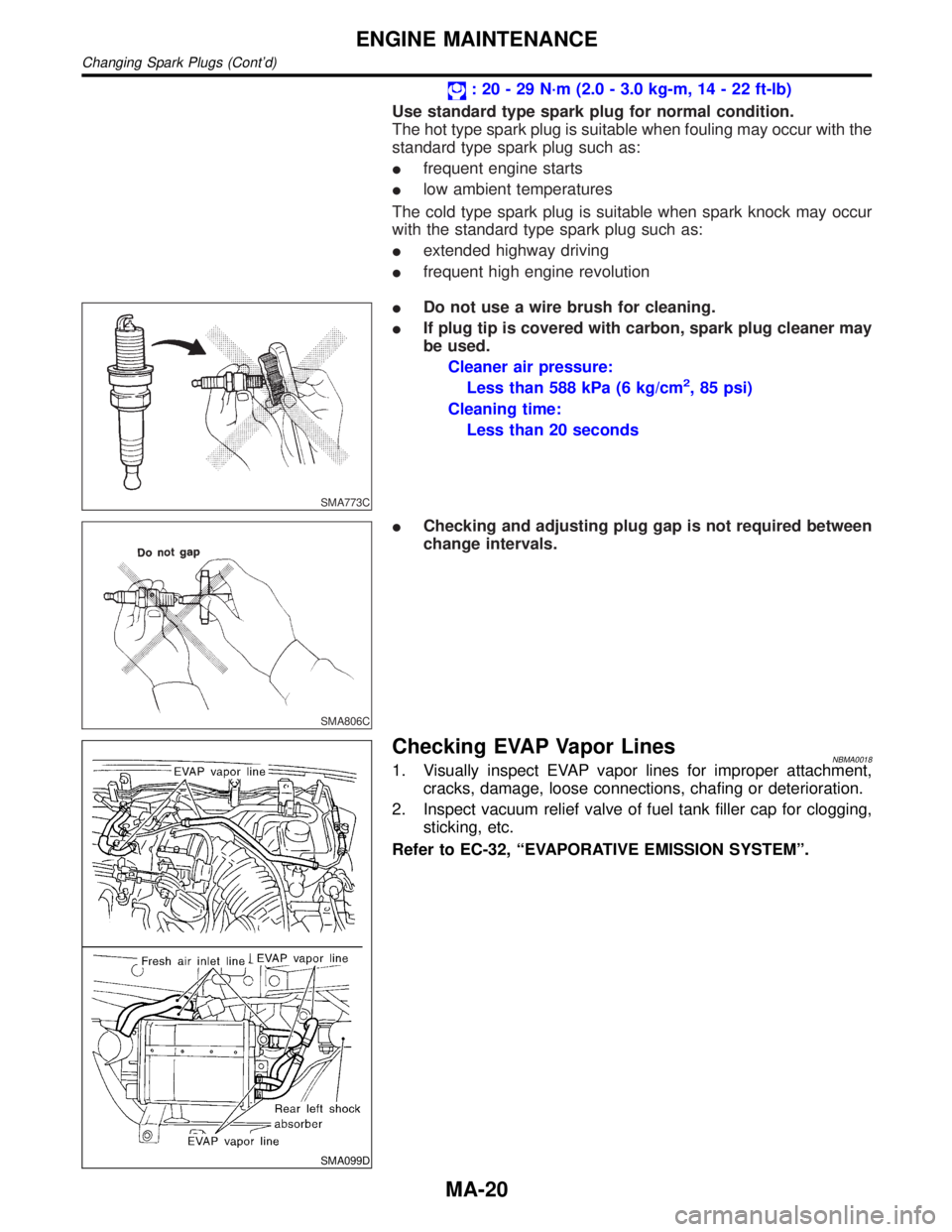
IDo not use a wire brush for cleaning.
IIf plug tip is covered with carbon, spark plug cleaner may
be used.
Cleaner air pressure:
Less than 588 kPa (6 kg/cm
2, 85 psi)
Cleaning time:
Less than 20 seconds
SMA806C
IChecking and adjusting plug gap is not required between
change intervals.
SMA099D
Checking EVAP Vapor LinesNBMA00181. Visually inspect EVAP vapor lines for improper attachment,
cracks, damage, loose connections, chafing or deterioration.
2. Inspect vacuum relief valve of fuel tank filler cap for clogging,
sticking, etc.
Refer to EC-32, ªEVAPORATIVE EMISSION SYSTEMº.
ENGINE MAINTENANCE
Changing Spark Plugs (Cont'd)
MA-20
Page 2016 of 2395
SMA211A
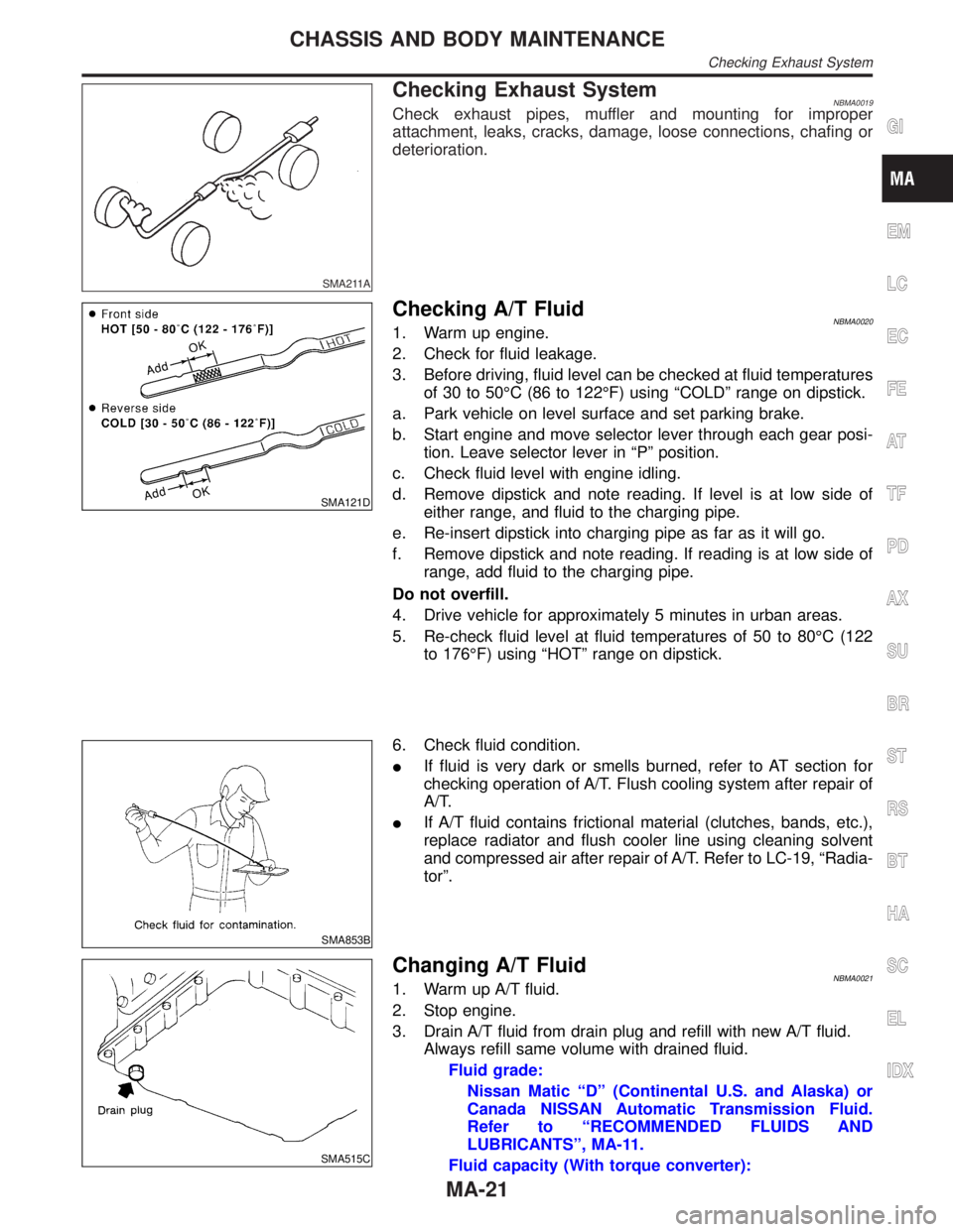
Checking Exhaust SystemNBMA0019Check exhaust pipes, muffler and mounting for improper
attachment, leaks, cracks, damage, loose connections, chafing or
deterioration.
SMA121D
Checking A/T FluidNBMA00201. Warm up engine.
2. Check for fluid leakage.
3. Before driving, fluid level can be checked at fluid temperatures
of 30 to 50ÉC (86 to 122ÉF) using ªCOLDº range on dipstick.
a. Park vehicle on level surface and set parking brake.
b. Start engine and move selector lever through each gear posi-
tion. Leave selector lever in ªPº position.
c. Check fluid level with engine idling.
d. Remove dipstick and note reading. If level is at low side of
either range, and fluid to the charging pipe.
e. Re-insert dipstick into charging pipe as far as it will go.
f. Remove dipstick and note reading. If reading is at low side of
range, add fluid to the charging pipe.
Do not overfill.
4. Drive vehicle for approximately 5 minutes in urban areas.
5. Re-check fluid level at fluid temperatures of 50 to 80ÉC (122
to 176ÉF) using ªHOTº range on dipstick.
SMA853B
6. Check fluid condition.
IIf fluid is very dark or smells burned, refer to AT section for
checking operation of A/T. Flush cooling system after repair of
A/T.
IIf A/T fluid contains frictional material (clutches, bands, etc.),
replace radiator and flush cooler line using cleaning solvent
and compressed air after repair of A/T. Refer to LC-19, ªRadia-
torº.
SMA515C
Changing A/T FluidNBMA00211. Warm up A/T fluid.
2. Stop engine.
3. Drain A/T fluid from drain plug and refill with new A/T fluid.
Always refill same volume with drained fluid.
Fluid grade:
Nissan Matic ªDº (Continental U.S. and Alaska) or
Canada NISSAN Automatic Transmission Fluid.
Refer to ªRECOMMENDED FLUIDS AND
LUBRICANTSº, MA-11.
Fluid capacity (With torque converter):
GI
EM
LC
EC
FE
AT
TF
PD
AX
SU
BR
ST
RS
BT
HA
SC
EL
IDX
CHASSIS AND BODY MAINTENANCE
Checking Exhaust System
MA-21
Page 2038 of 2395
Preparation
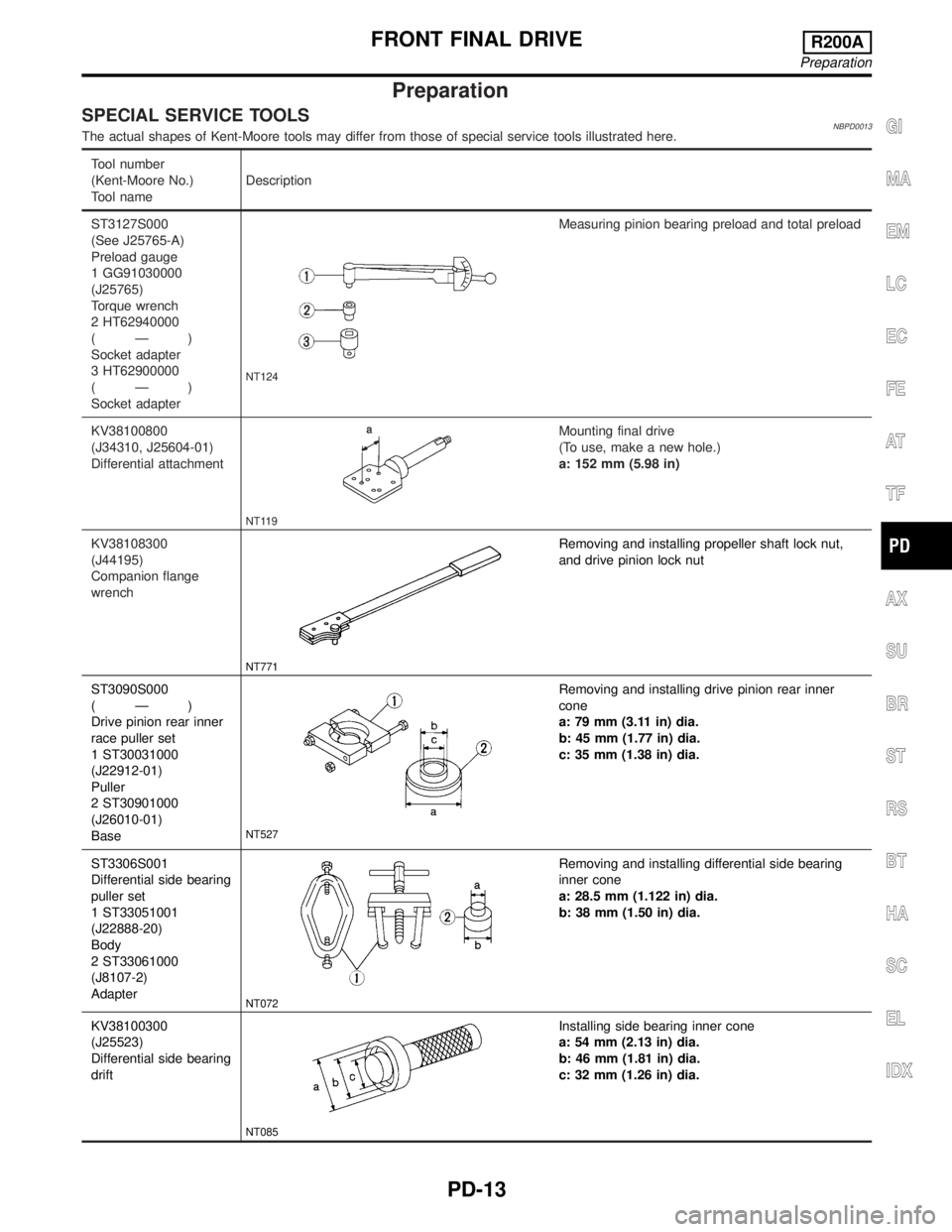
SPECIAL SERVICE TOOLSNBPD0013The actual shapes of Kent-Moore tools may differ from those of special service tools illustrated here.
Tool number
(Kent-Moore No.)
Tool nameDescription
ST3127S000
(See J25765-A)
Preload gauge
1 GG91030000
(J25765)
Torque wrench
2 HT62940000
(Ð)
Socket adapter
3 HT62900000
(Ð)
Socket adapter
NT124
Measuring pinion bearing preload and total preload
KV38100800
(J34310, J25604-01)
Differential attachment
NT119
Mounting final drive
(To use, make a new hole.)
a: 152 mm (5.98 in)
KV38108300
(J44195)
Companion flange
wrench
NT771
Removing and installing propeller shaft lock nut,
and drive pinion lock nut
ST3090S000
(Ð)
Drive pinion rear inner
race puller set
1 ST30031000
(J22912-01)
Puller
2 ST30901000
(J26010-01)
Base
NT527
Removing and installing drive pinion rear inner
cone
a: 79 mm (3.11 in) dia.
b: 45 mm (1.77 in) dia.
c: 35 mm (1.38 in) dia.
ST3306S001
Differential side bearing
puller set
1 ST33051001
(J22888-20)
Body
2 ST33061000
(J8107-2)
Adapter
NT072
Removing and installing differential side bearing
inner cone
a: 28.5 mm (1.122 in) dia.
b: 38 mm (1.50 in) dia.
KV38100300
(J25523)
Differential side bearing
drift
NT085
Installing side bearing inner cone
a: 54 mm (2.13 in) dia.
b: 46 mm (1.81 in) dia.
c: 32 mm (1.26 in) dia.
GI
MA
EM
LC
EC
FE
AT
TF
AX
SU
BR
ST
RS
BT
HA
SC
EL
IDX
FRONT FINAL DRIVER200A
Preparation
PD-13
Page 2043 of 2395
Removal and InstallationNBPD0017REMOVALNBPD0017S01IRemove front of propeller shaft.
Plug front end of transfer.
IRemove drive shaft. Refer to AX-11, ªRemovalº.
IRemove front final drive mounting bolts.
CAUTION:
Be careful not to damage spline, sleeve yoke and front oil seal
when removing propeller shaft.
SPD123
INSTALLATIONNBPD0017S02IFill final drive with recommended gear oil.
SPD664
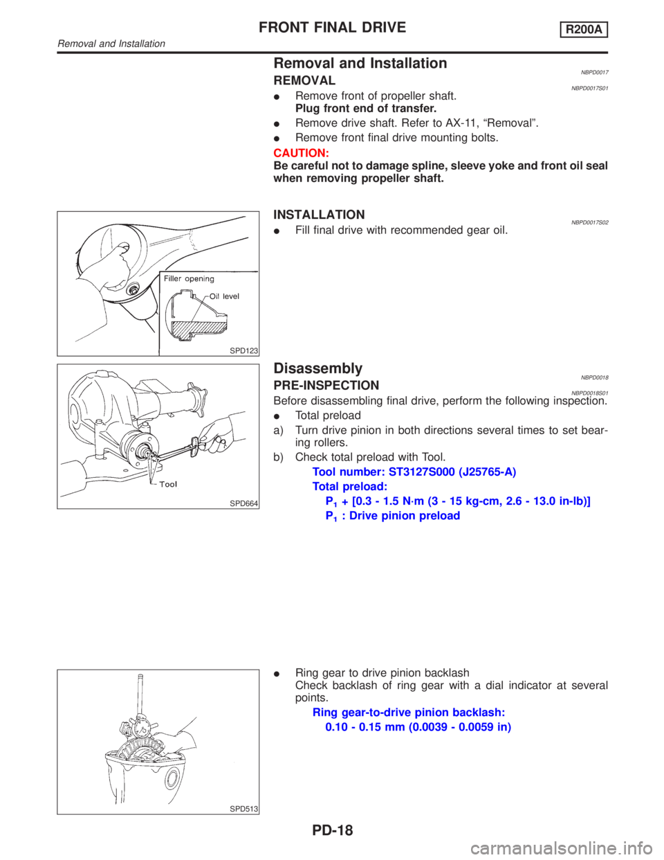
DisassemblyNBPD0018PRE-INSPECTIONNBPD0018S01Before disassembling final drive, perform the following inspection.
ITotal preload
a) Turn drive pinion in both directions several times to set bear-
ing rollers.
b) Check total preload with Tool.
Tool number: ST3127S000 (J25765-A)
Total preload:
P
1+ [0.3 - 1.5 N´m (3 - 15 kg-cm, 2.6 - 13.0 in-lb)]
P
1: Drive pinion preload
SPD513
IRing gear to drive pinion backlash
Check backlash of ring gear with a dial indicator at several
points.
Ring gear-to-drive pinion backlash:
0.10 - 0.15 mm (0.0039 - 0.0059 in)
FRONT FINAL DRIVER200A
Removal and Installation
PD-18
Page 2050 of 2395
SPD194A
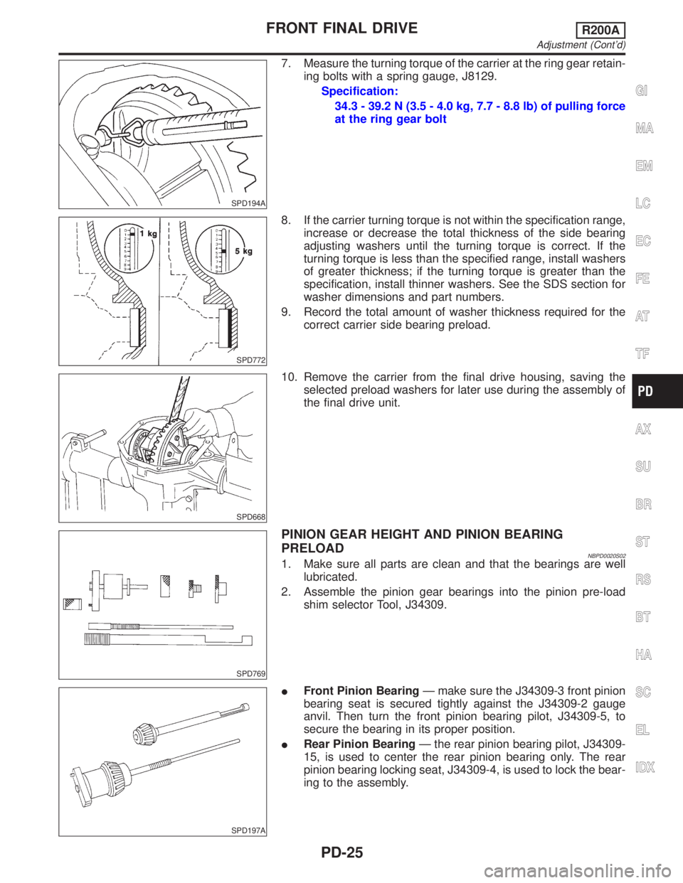
7. Measure the turning torque of the carrier at the ring gear retain-
ing bolts with a spring gauge, J8129.
Specification:
34.3 - 39.2 N (3.5 - 4.0 kg, 7.7 - 8.8 lb) of pulling force
at the ring gear bolt
SPD772
8. If the carrier turning torque is not within the specification range,
increase or decrease the total thickness of the side bearing
adjusting washers until the turning torque is correct. If the
turning torque is less than the specified range, install washers
of greater thickness; if the turning torque is greater than the
specification, install thinner washers. See the SDS section for
washer dimensions and part numbers.
9. Record the total amount of washer thickness required for the
correct carrier side bearing preload.
SPD668
10. Remove the carrier from the final drive housing, saving the
selected preload washers for later use during the assembly of
the final drive unit.
SPD769
PINION GEAR HEIGHT AND PINION BEARING
PRELOAD
NBPD0020S021. Make sure all parts are clean and that the bearings are well
lubricated.
2. Assemble the pinion gear bearings into the pinion pre-load
shim selector Tool, J34309.
SPD197A
IFront Pinion BearingÐ make sure the J34309-3 front pinion
bearing seat is secured tightly against the J34309-2 gauge
anvil. Then turn the front pinion bearing pilot, J34309-5, to
secure the bearing in its proper position.
IRear Pinion BearingÐ the rear pinion bearing pilot, J34309-
15, is used to center the rear pinion bearing only. The rear
pinion bearing locking seat, J34309-4, is used to lock the bear-
ing to the assembly.
GI
MA
EM
LC
EC
FE
AT
TF
AX
SU
BR
ST
RS
BT
HA
SC
EL
IDX
FRONT FINAL DRIVER200A
Adjustment (Cont'd)
PD-25
Page 2063 of 2395
Preparation
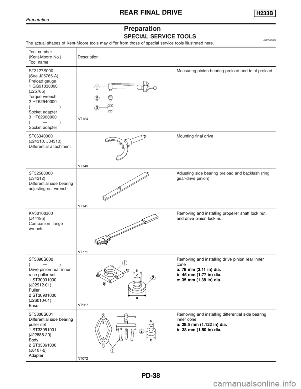
SPECIAL SERVICE TOOLSNBPD0029The actual shapes of Kent-Moore tools may differ from those of special service tools illustrated here.
Tool number
(Kent-Moore No.)
Tool nameDescription
ST3127S000
(See J25765-A)
Preload gauge
1 GG91030000
(J25765)
Torque wrench
2 HT62940000
(Ð)
Socket adapter
3 HT62900000
(Ð)
Socket adapter
NT124
Measuring pinion bearing preload and total preload
ST06340000
(J24310, J34310)
Differential attachment
NT140
Mounting final drive
ST32580000
(J34312)
Differential side bearing
adjusting nut wrench
NT141
Adjusting side bearing preload and backlash (ring
gear-drive pinion)
KV38108300
(J44195)
Companion flange
wrench
NT771
Removing and installing propeller shaft lock nut,
and drive pinion lock nut
ST3090S000
(Ð)
Drive pinion rear inner
race puller set
1 ST30031000
(J22912-01)
Puller
2 ST30901000
(J26010-01)
Base
NT527
Removing and installing drive pinion rear inner
cone
a: 79 mm (3.11 in) dia.
b: 45 mm (1.77 in) dia.
c: 35 mm (1.38 in) dia.
ST3306S001
Differential side bearing
puller set
1 ST33051001
(J22888-20)
Body
2 ST33061000
(J8107-2)
Adapter
NT072
Removing and installing differential side bearing
inner cone
a: 28.5 mm (1.122 in) dia.
b: 38 mm (1.50 in) dia.
REAR FINAL DRIVEH233B
Preparation
PD-38