2001 INFINITI QX4 vin
[x] Cancel search: vinPage 2068 of 2395
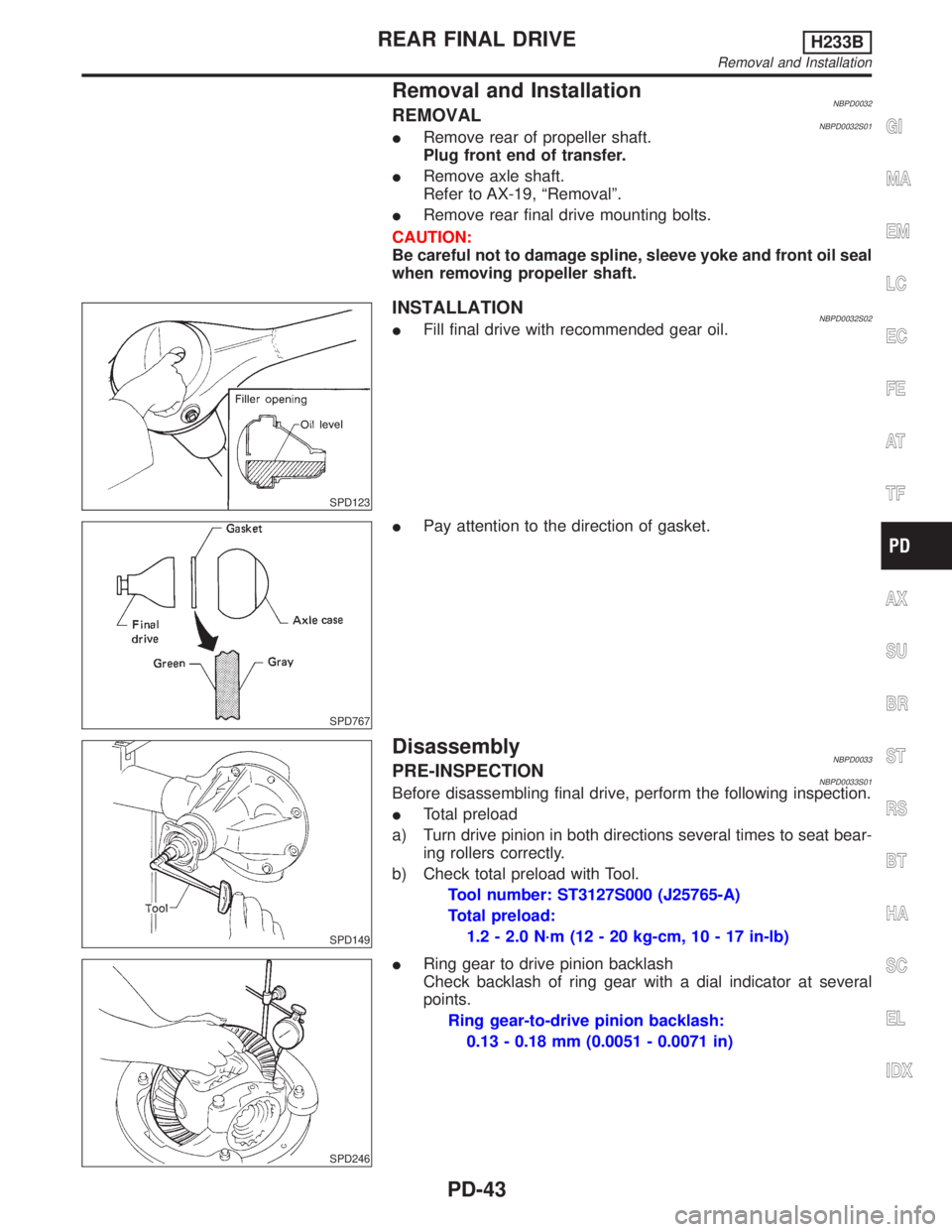
Removal and InstallationNBPD0032REMOVALNBPD0032S01IRemove rear of propeller shaft.
Plug front end of transfer.
IRemove axle shaft.
Refer to AX-19, ªRemovalº.
IRemove rear final drive mounting bolts.
CAUTION:
Be careful not to damage spline, sleeve yoke and front oil seal
when removing propeller shaft.
SPD123
INSTALLATIONNBPD0032S02IFill final drive with recommended gear oil.
SPD767
IPay attention to the direction of gasket.
SPD149
DisassemblyNBPD0033PRE-INSPECTIONNBPD0033S01Before disassembling final drive, perform the following inspection.
ITotal preload
a) Turn drive pinion in both directions several times to seat bear-
ing rollers correctly.
b) Check total preload with Tool.
Tool number: ST3127S000 (J25765-A)
Total preload:
1.2 - 2.0 N´m (12 - 20 kg-cm, 10 - 17 in-lb)
SPD246
IRing gear to drive pinion backlash
Check backlash of ring gear with a dial indicator at several
points.
Ring gear-to-drive pinion backlash:
0.13 - 0.18 mm (0.0051 - 0.0071 in)
GI
MA
EM
LC
EC
FE
AT
TF
AX
SU
BR
ST
RS
BT
HA
SC
EL
IDX
REAR FINAL DRIVEH233B
Removal and Installation
PD-43
Page 2075 of 2395
SPD381A
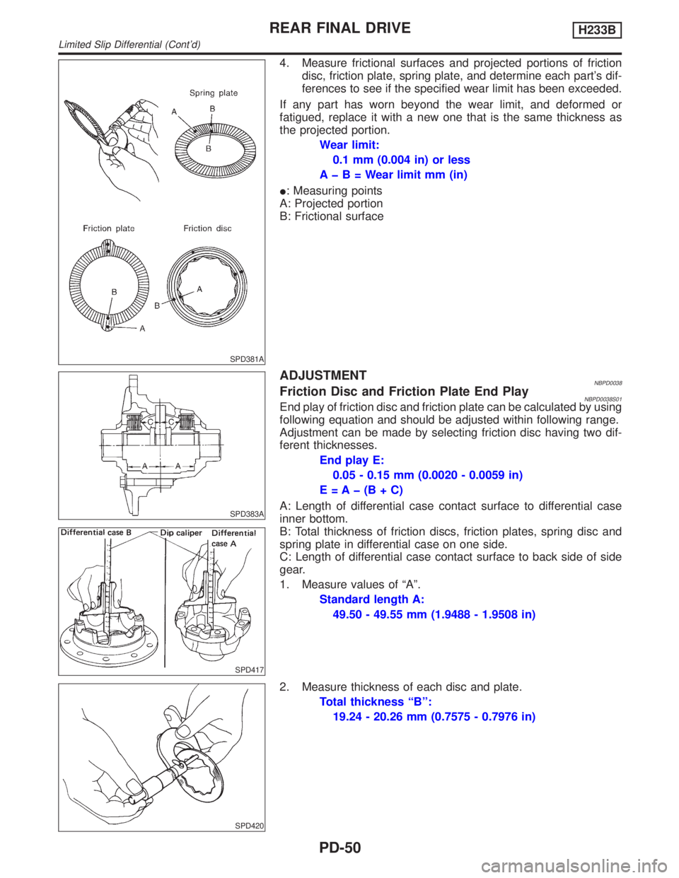
4. Measure frictional surfaces and projected portions of friction
disc, friction plate, spring plate, and determine each part's dif-
ferences to see if the specified wear limit has been exceeded.
If any part has worn beyond the wear limit, and deformed or
fatigued, replace it with a new one that is the same thickness as
the projected portion.
Wear limit:
0.1 mm (0.004 in) or less
AþB=Wearlimit mm (in)
I: Measuring points
A: Projected portion
B: Frictional surface
SPD383A
SPD417
ADJUSTMENTNBPD0038Friction Disc and Friction Plate End PlayNBPD0038S01End play of friction disc and friction plate can be calculated by using
following equation and should be adjusted within following range.
Adjustment can be made by selecting friction disc having two dif-
ferent thicknesses.
End play E:
0.05 - 0.15 mm (0.0020 - 0.0059 in)
E=Aþ(B+C)
A: Length of differential case contact surface to differential case
inner bottom.
B: Total thickness of friction discs, friction plates, spring disc and
spring plate in differential case on one side.
C: Length of differential case contact surface to back side of side
gear.
1. Measure values of ªAº.
Standard length A:
49.50 - 49.55 mm (1.9488 - 1.9508 in)
SPD420
2. Measure thickness of each disc and plate.
Total thickness ªBº:
19.24 - 20.26 mm (0.7575 - 0.7976 in)
REAR FINAL DRIVEH233B
Limited Slip Differential (Cont'd)
PD-50
Page 2092 of 2395
Precautions
SUPPLEMENTAL RESTRAINT SYSTEM (SRS) ªAIR BAGº AND ªSEAT BELT
PRE-TENSIONERº
NBRS0001The Supplemental Restraint System such as ªAIR BAGº and ªSEAT BELT PRE-TENSIONERº used along with
a seat belt, helps to reduce the risk or severity of injury to the driver and front passenger for certain types of
collision. The SRS composition which is available to INFINITI QX4 is as follows:
IFor a frontal collision
The Supplemental Restraint System consists of driver air bag module (located in the center of the steer-
ing wheel), front passenger air bag module (located on the instrument panel on passenger side), seat belt
pre-tensioners, a diagnosis sensor unit, warning lamp, wiring harness and spiral cable.
IFor a side collision
The Supplemental Restraint System consists of side air bag module (located in the outer side of front seat),
satellite sensor, diagnosis sensor unit (one of components of air bags for a frontal collision), wiring harness,
warning lamp (one of components of air bags for a frontal collision).
WARNING:
ITo avoid rendering the SRS inoperative, which could increase the risk of personal injury or death
in the event of a collision which would result in air bag inflation, all maintenance must be performed
by an authorized INFINITI dealer.
IImproper maintenance, including incorrect removal and installation of the SRS, can lead to per-
sonal injury caused by unintentional activation of the system.
IDo not use electrical test equipment on any circuit related to the SRS unless instructed to in this
Service Manual. Spiral cable and wiring harnesses covered with yellow insulation tape either just
before the harness connectors or for the complete harness are related to the SRS.
PRECAUTION FOR SEAT BELT SERVICENBRS0002CAUTION:
IBefore removing the seat belt pre-tensioner assembly, turn the ignition switch off, disconnect both
battery cables and wait at least 3 minutes.
IDo not use electrical test equipment for seat belt pre-tensioner connector.
IAfter replacing or reinstalling seat belt pre-tensioner assembly, or reconnecting seat belt pre-ten-
sioner connector, check the system function. Refer to ªSRS Operation Checkº (RS-38) for details.
IDo not use disassemble buckle or seat belt assembly.
IReplace anchor bolts if they are deformed or worn out.
INever oil tongue and buckle.
IIf any component of seat belt assembly is questionable, do not repair. Replace the whole seat belt
assembly.
IIf webbing is cut, frayed, or damaged, replace seat belt assembly.
IWhen replacing seat belt assembly, use a genuine seat belt assembly.
After A CollisionNBRS0002S01WARNING:
Inspect all seat belt assemblies including retractors and attaching hardware after any collision.
NISSAN recommends that all seat belt assemblies in use during a collision be replaced unless the
collision was minor and the belts show no damage and continue to operate properly. Failure to do so
could result in serious personal injury in an accident. Seat belt assemblies not in use during a colli-
sion should also be replaced if either damage or improper operation is noted. Seat belt pre-tensioner
should be replaced even if the seat belts are not in use during a frontal collision in which the air bags
are deployed.
Replace any seat belt assembly if:
IThe seat belt was in use at the time of a collision (except for minor collisions and the belts, retractors and
buckles show no damage and continue to operate properly).
IThe seat belt was damaged in an accident. (i.e. torn webbing, bent retractor or guide, etc.)
IThe seat belt attaching point was damaged in an accident. Inspect the seat belt attaching area for dam-
age or distortion and repair as necessary before installing a new seat belt assembly.
IAnchor bolts are deformed or worn out.
IThe seat belt pre-tensioner should be replaced even if the seat belts are not in use during the collision in
which the air bags are deployed.
GI
MA
EM
LC
EC
FE
AT
TF
PD
AX
SU
BR
ST
BT
HA
SC
EL
IDX
SEAT BELTS
Precautions
RS-3
Page 2097 of 2395
SEAT BELT RETRACTOR ON-VEHICLE CHECKNBRS0029S03Emergency Locking Retractors (ELR) and Automatic Locking Retractors (ALR)NBRS0029S0301NOTE:
All seat belt retractors are of the Emergency Locking Retractors (ELR) type. In an emergency (sudden stop)
the retractor will lock and prevent the belt from extending any further. All 3-point type seat belt retractors except
the driver's seat belt also have an Automatic Locking Retractors (ALR) mode. The ALR mode (also called child
restraint mode) is used when installing child seats. The ALR mode is activated when the seat belt is fully
extended. When the belt is then retracted partially, the ALR mode automatically locks the seat belt in a spe-
cific position so the belt cannot be extended any further. To cancel the ALR mode, allow the seat belt to fully
wind back into the retractor.
Check the seat belt retractors using the following test(s) to determine if a retractor assembly is operating
properly.
ELR Function Stationary CheckNBRS0029S0302Grasp the shoulder belt and pull forward quickly. The retractor should lock and prevent the belt from extend-
ing further.
ALR Function Stationary CheckNBRS0029S03041. Pull out entire length of seat belt from retractor until a click is heard.
2. Retract the belt partially. A clicking noise should be heard as the belt retracts indicating that the retractor
is in the Automatic Locking Retractors (ALR) mode.
3. Grasp the seat belt and try to pull out the retractor. The belt must lock and not extend any further. If NG,
replace the retractor assembly.
4. Allow the entire length of the belt to retract to cancel the automatic locking mode.
ELR Function Moving CheckNBRS0029S0303WARNING:
Perform the following test in a safe, open area clear of other vehicles and obstructions (for example,
a large, empty parking lot). Road surface must be paved and dry. DO NOT perform the following test
on wet or gravel roads or on public streets and highways. This could result in an accident and seri-
ous personal injury. The driver and passenger must be prepared to brace themselves in the event the
retractor does not lock.
1. Fasten driver's seat belt. Buckle a passenger into the seat for the belt that is to be tested.
2. Proceed to the designated safe area.
3. Drive the vehicle at approximately 16 km/h (10 MPH). Notify any passengers of a pending sudden stop
and the driver and passenger must be prepared to brace themselves in the event the retractor does not
lock, apply brakes firmly and make a very hard stop.
During stop, seat belts should lock and not be extended. If the seat belt retractor assembly does not lock,
perform the retractor off-vehicle check.
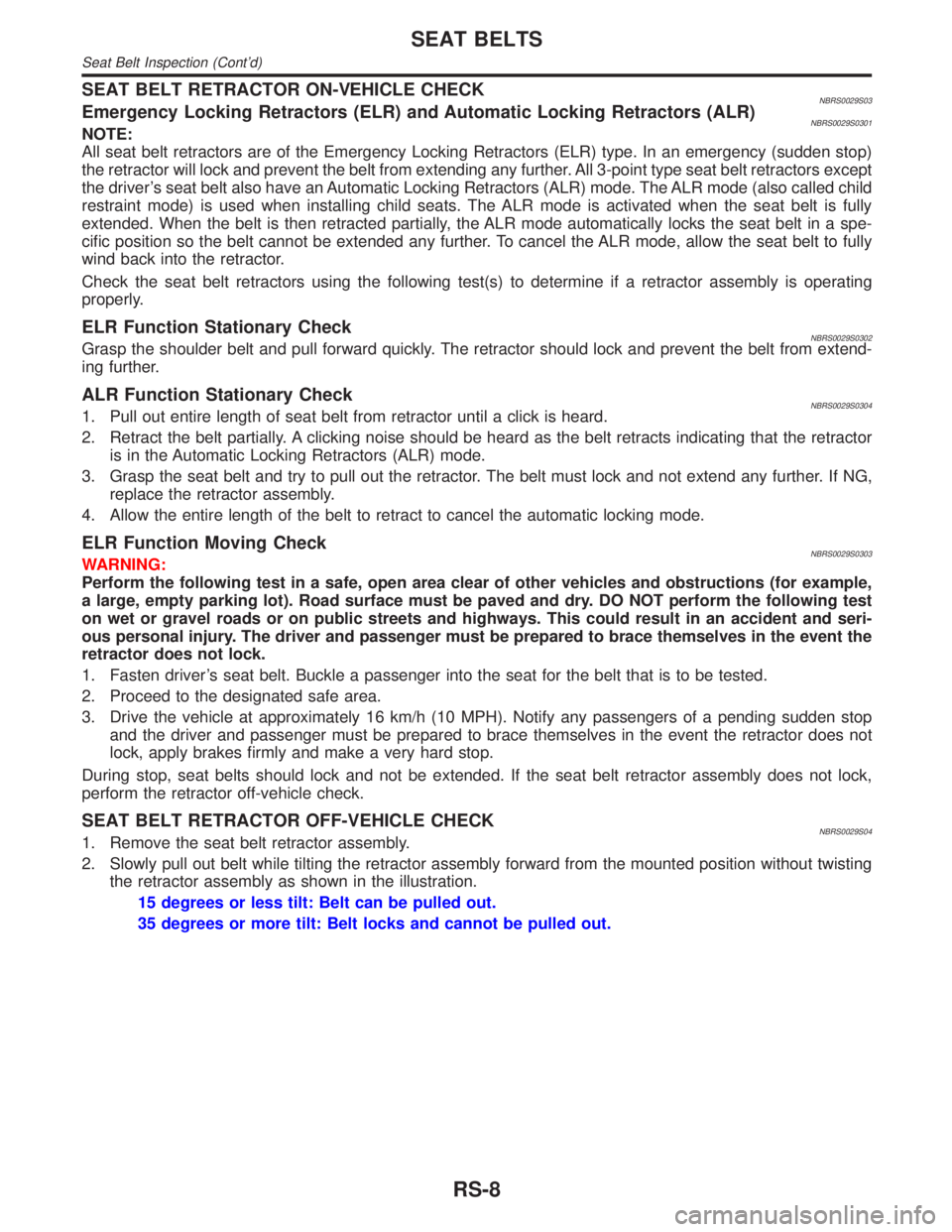
SEAT BELT RETRACTOR OFF-VEHICLE CHECKNBRS0029S041. Remove the seat belt retractor assembly.
2. Slowly pull out belt while tilting the retractor assembly forward from the mounted position without twisting
the retractor assembly as shown in the illustration.
15 degrees or less tilt: Belt can be pulled out.
35 degrees or more tilt: Belt locks and cannot be pulled out.
SEAT BELTS
Seat Belt Inspection (Cont'd)
RS-8
Page 2184 of 2395
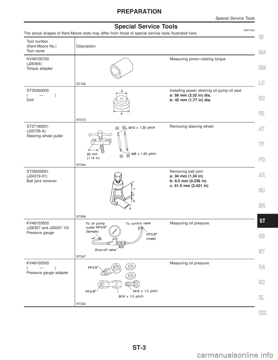
Special Service ToolsNBST0003The actual shapes of Kent-Moore tools may differ from those of special service tools illustrated here.
Tool number
(Kent-Moore No.)
Tool nameDescription
KV48100700
(J26364)
Torque adapter
NT169
Measuring pinion rotating torque
ST35300000
(Ð)
Drift
NT073
Installing power steering oil pump oil seal
a: 59 mm (2.32 in) dia.
b: 45 mm (1.77 in) dia.
ST27180001
(J25726-A)
Steering wheel puller
NT544
Removing steering wheel
ST29020001
(J24319-01)
Ball joint remover
NT694
Removing ball joint
a: 34 mm (1.34 in)
b: 6.5 mm (0.256 in)
c: 61.5 mm (2.421 in)
KV48103500
(J26357 and J26357-10)
Pressure gauge
NT547
Measuring oil pressure
KV48102500
(Ð)
Pressure gauge adapter
NT542
Measuring oil pressure
GI
MA
EM
LC
EC
FE
AT
TF
PD
AX
SU
BR
RS
BT
HA
SC
EL
IDX
PREPARATION
Special Service Tools
ST-3
Page 2185 of 2395
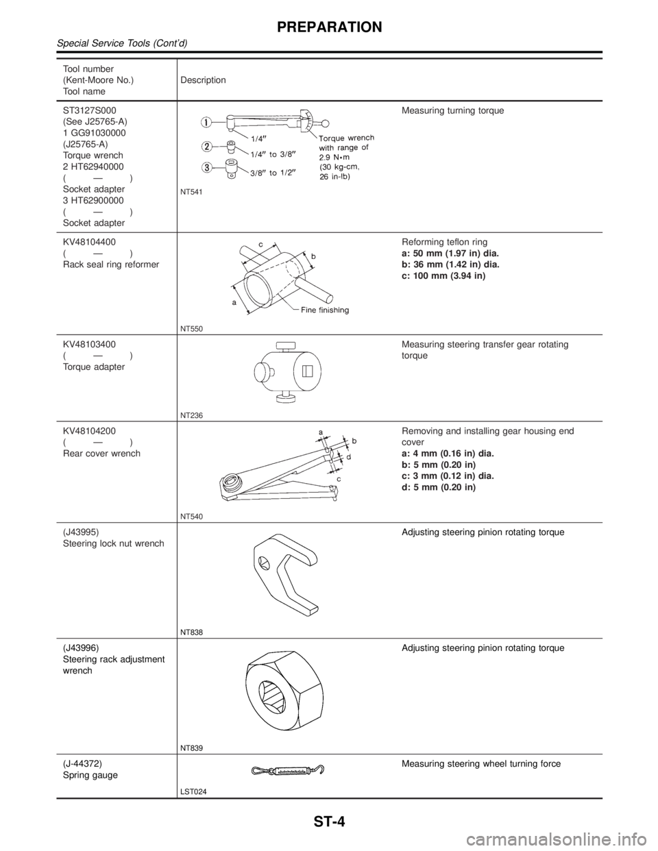
Tool number
(Kent-Moore No.)
Tool nameDescription
ST3127S000
(See J25765-A)
1 GG91030000
(J25765-A)
Torque wrench
2 HT62940000
(Ð)
Socket adapter
3 HT62900000
(Ð)
Socket adapter
NT541
Measuring turning torque
KV48104400
(Ð)
Rack seal ring reformer
NT550
Reforming teflon ring
a: 50 mm (1.97 in) dia.
b: 36 mm (1.42 in) dia.
c: 100 mm (3.94 in)
KV48103400
(Ð)
Torque adapter
NT236
Measuring steering transfer gear rotating
torque
KV48104200
(Ð)
Rear cover wrench
NT540
Removing and installing gear housing end
cover
a: 4 mm (0.16 in) dia.
b: 5 mm (0.20 in)
c: 3 mm (0.12 in) dia.
d: 5 mm (0.20 in)
(J43995)
Steering lock nut wrench
NT838
Adjusting steering pinion rotating torque
(J43996)
Steering rack adjustment
wrench
NT839
Adjusting steering pinion rotating torque
(J-44372)
Spring gauge
LST024
Measuring steering wheel turning force
PREPARATION
Special Service Tools (Cont'd)
ST-4
Page 2188 of 2395
SST489B
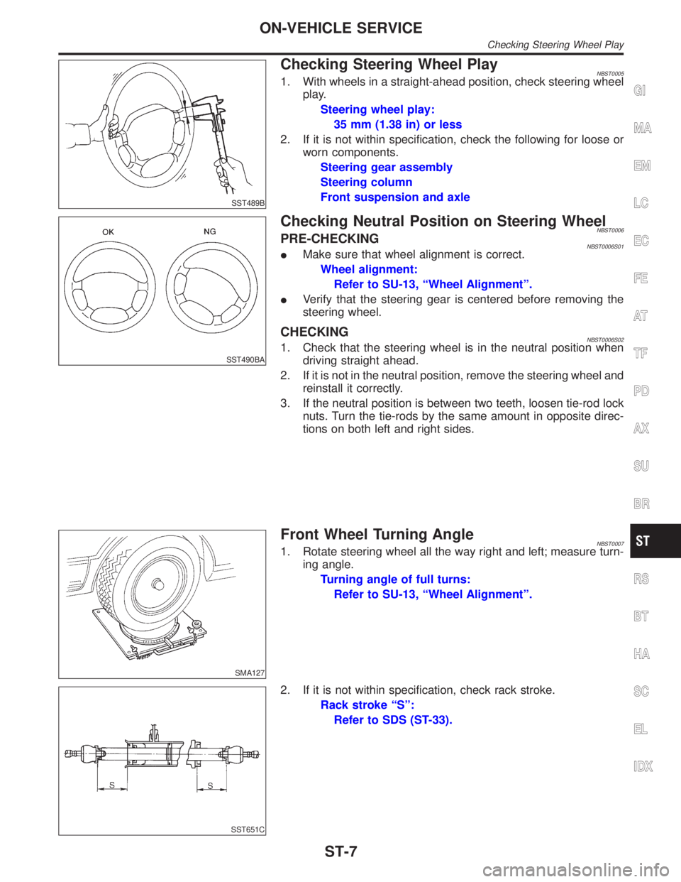
Checking Steering Wheel PlayNBST00051. With wheels in a straight-ahead position, check steering wheel
play.
Steering wheel play:
35 mm (1.38 in) or less
2. If it is not within specification, check the following for loose or
worn components.
Steering gear assembly
Steering column
Front suspension and axle
SST490BA
Checking Neutral Position on Steering WheelNBST0006PRE-CHECKINGNBST0006S01IMake sure that wheel alignment is correct.
Wheel alignment:
Refer to SU-13, ªWheel Alignmentº.
IVerify that the steering gear is centered before removing the
steering wheel.
CHECKINGNBST0006S021. Check that the steering wheel is in the neutral position when
driving straight ahead.
2. If it is not in the neutral position, remove the steering wheel and
reinstall it correctly.
3. If the neutral position is between two teeth, loosen tie-rod lock
nuts. Turn the tie-rods by the same amount in opposite direc-
tions on both left and right sides.
SMA127
Front Wheel Turning AngleNBST00071. Rotate steering wheel all the way right and left; measure turn-
ing angle.
Turning angle of full turns:
Refer to SU-13, ªWheel Alignmentº.
SST651C
2. If it is not within specification, check rack stroke.
Rack stroke ªSº:
Refer to SDS (ST-33).
GI
MA
EM
LC
EC
FE
AT
TF
PD
AX
SU
BR
RS
BT
HA
SC
EL
IDX
ON-VEHICLE SERVICE
Checking Steering Wheel Play
ST-7
Page 2189 of 2395
SST601C
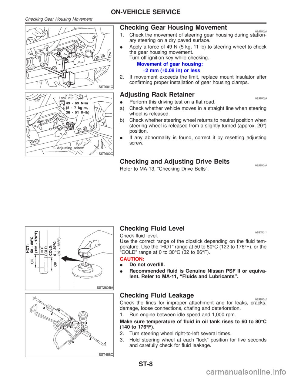
Checking Gear Housing MovementNBST00081. Check the movement of steering gear housing during station-
ary steering on a dry paved surface.
IApply a force of 49 N (5 kg, 11 lb) to steering wheel to check
the gear housing movement.
Turn off ignition key while checking.
Movement of gear housing:
±2mm(±0.08 in) or less
2. If movement exceeds the limit, replace mount insulator after
confirming proper installation of gear housing clamps.
SST602C
Adjusting Rack RetainerNBST0009IPerform this driving test on a flat road.
a) Check whether vehicle moves in a straight line when steering
wheel is released.
b) Check whether steering wheel returns to neutral position when
steering wheel is released from a slightly turned (approx. 20É)
position.
IIf any abnormality is found, correct it by resetting adjusting
screw.
Checking and Adjusting Drive BeltsNBST0010Refer to MA-13, ªChecking Drive Beltsº.
SST280BA
Checking Fluid LevelNBST0011Check fluid level.
Use the correct range of the dipstick depending on the fluid tem-
perature. Use the ªHOTº range at 50 to 80ÉC (122 to 176ÉF), or the
ªCOLDº range at 0 to 30ÉC (32 to 86ÉF).
CAUTION:
IDo not overfill.
IRecommended fluid is Genuine Nissan PSF II or equiva-
lent. Refer to MA-11, ªFluids and Lubricantsº.
SST458C
Checking Fluid LeakageNBST0012Check the lines for improper attachment and for leaks, cracks,
damage, loose connections, chafing and deterioration.
1. Run engine between idle speed and 1,000 rpm.
Make sure temperature of fluid in oil tank rises to 60 to 80ÉC
(140 to 176ÉF).
2. Turn steering wheel right-to-left several times.
3. Hold steering wheel at each ªlockº position for five seconds
and carefully check for fluid leakage.
ON-VEHICLE SERVICE
Checking Gear Housing Movement
ST-8