Page 2329 of 2395
Diagnostic ProcedureNBTF0066
1 SHIFT ACTUATOR CIRCUIT
Refer to ªTransfer Shift Relay (High & Low)º, ªCOMPONENT INSPECTIONº and ªActuator & Actuator Position Switchº,
ªCOMPONENT INSPECTIONº, TF-114, 115.
OK or NG
OK©GO TO 2.
NG©Repair or replace transfer shift relay and actuator and actuator position switch.
2 CHECK POWER SOURCE OF TRANSFER SHIFT (HI & LOW) RELAY
SMT825DA
1. Disconnect transfer control device terminal.
2. Turn ignition switch to ªONº (Do not start engine).
3. Check voltage between transfer shift HI and LOW relay terminal 5 and body ground.
Voltage: Battery voltage
SMT831D
OK or NG
OK©GO TO 3.
NG©Check the following.
IContinuity between ignition switch and transfer shift HI & LOW relays
ICheck ground circuit between transfer shift HI & LOW relays and body ground.
IIgnition switch and No. 3 fuse (20A)
SHIFT ACTUATOR CIRCUIT
Diagnostic Procedure
TF-94
Page 2330 of 2395
3 CHECK POWER SOURCE OF TRANSFER CONTROL DEVICE
1. Disconnect transfer control device terminal.
2. Turn ignition switch to ªONº. (Do not start engine.)
3. Turn 4WD shift switch from ª4Hº to ª4LOº (or from ª4LOº to ª4Hº).
4. Check voltage between transfer control device terminal 3 (or 4) and body ground.
Voltage: Battery voltage
SMT832D
OK or NG
OK©GO TO 4.
NG©Check the following.
IHarness and connector from transfer shift HI and LOW relays to transfer control
device harness terminal
IGround circuit between transfer control device and body ground.
4 CHECK INPUT SIGNAL
WITH CONSULT-II©GO TO 5.
WITHOUT CONSULT-II©GO TO 6.
GI
MA
EM
LC
EC
FE
AT
PD
AX
SU
BR
ST
RS
BT
HA
SC
EL
IDX
SHIFT ACTUATOR CIRCUIT
Diagnostic Procedure (Cont'd)
TF-95
Page 2333 of 2395
Symptom 1. 4WD Shift Indicator Lamp Does
Not Turn ON
NBTF0029SYMPTOM: Although ignition switch is turned ªONº, all the
4WD shift indicator lamps do not turn ON for 1 second.
1 CHECK TRANSFER CONTROL UNIT POWER SOURCE
SMT958D
SMT860D
1. Turn ignition switch to ªOFFº position and disconnect transfer control unit harness connector.
2. Turn ignition switch to ªONº position. (Do not start engine.)
3. Check voltage between transfer control unit harness connector terminals 16, 22 and body ground.
Voltage: Battery voltage
SMT796D
OK or NG
OK©GO TO 2.
NG©Check the following.
IContinuity between ignition switch and transfer control unit
IIgnition switch and No. 18 fuse (10A)
TROUBLE DIAGNOSES FOR SYMPTOMS
Symptom 1. 4WD Shift Indicator Lamp Does Not Turn ON
TF-98
Page 2335 of 2395
Symptom 2. 4WD Warning Lamp Does Not Turn
ON
=NBTF0030SYMPTOM: Although ignition switch is turned ªONº, 4WD
warning lamp does not turn ON.
1 CHECK TRANSFER CONTROL UNIT POWER SOURCE
SMT799D
1. Turn ignition switch to ªOFFº position and disconnect transfer control unit harness connector.
2. Turn ignition switch to ªONº position.
(Do not start engine.)
3. Check voltage between transfer control unit harness connector terminals 16, 22 and body ground.
Voltage: Battery voltage
SMT800D
OK or NG
OK©GO TO 2.
NG©Check the following.
IContinuity between ignition switch and transfer control unit
IIgnition switch and No. 18 fuse (10A)
TROUBLE DIAGNOSES FOR SYMPTOMS
Symptom 2. 4WD Warning Lamp Does Not Turn ON
TF-100
Page 2339 of 2395
Symptom 5. 4LO Indicator Lamp Does Not Turn
ON
=NBTF0033SYMPTOM: When 4WD shift switch is set from ª4Hº to
ª4LOº position, 4LO indicator lamp does not turn ON.
1 CHECK TRANSFER CONTROL UNIT POWER SUPPLY CIRCUIT
SMT958D
SMT851D
SMT979D
1. Disconnect battery negative terminal (þ), then transfer control unit connector.
2. Connect battery negative terminal (þ) and turn ignition switch ªONº (with engine stopped).
3. Check voltage across transfer control unit body-side connector terminals 47, 16 and body ground.
Voltage: Battery voltage
OK or NG
OK©GO TO 2.
NG©Check the following.
IContinuity between battery and transfer control unit
IIgnition switch (Refer to EL-9, ªPower Supply Routingº.)
INo. 24 fuse (7.5A), No. 8 fuse (10A) and No. 18 fuse (10A)
TROUBLE DIAGNOSES FOR SYMPTOMS
Symptom 5. 4LO Indicator Lamp Does Not Turn ON
TF-104
Page 2340 of 2395

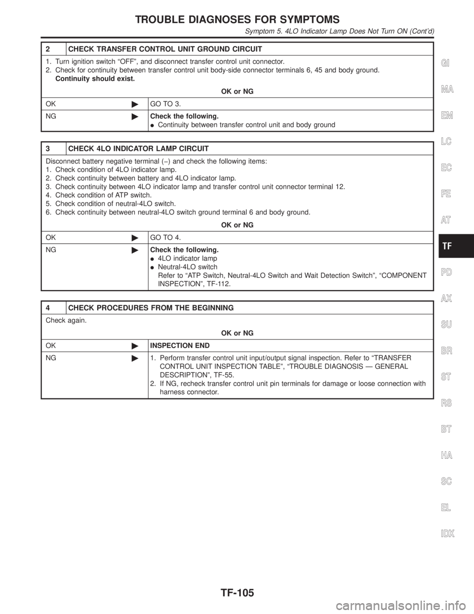
2 CHECK TRANSFER CONTROL UNIT GROUND CIRCUIT
1. Turn ignition switch ªOFFº, and disconnect transfer control unit connector.
2. Check for continuity between transfer control unit body-side connector terminals 6, 45 and body ground.
Continuity should exist.
OK or NG
OK©GO TO 3.
NG©Check the following.
IContinuity between transfer control unit and body ground
3 CHECK 4LO INDICATOR LAMP CIRCUIT
Disconnect battery negative terminal (þ) and check the following items:
1. Check condition of 4LO indicator lamp.
2. Check continuity between battery and 4LO indicator lamp.
3. Check continuity between 4LO indicator lamp and transfer control unit connector terminal 12.
4. Check condition of ATP switch.
5. Check condition of neutral-4LO switch.
6. Check continuity between neutral-4LO switch ground terminal 6 and body ground.
OK or NG
OK©GO TO 4.
NG©Check the following.
I4LO indicator lamp
INeutral-4LO switch
Refer to ªATP Switch, Neutral-4LO Switch and Wait Detection Switchº, ªCOMPONENT
INSPECTIONº, TF-112.
4 CHECK PROCEDURES FROM THE BEGINNING
Check again.
OK or NG
OK©INSPECTION END
NG©1. Perform transfer control unit input/output signal inspection. Refer to ªTRANSFER
CONTROL UNIT INSPECTION TABLEº, ªTROUBLE DIAGNOSIS Ð GENERAL
DESCRIPTIONº, TF-55.
2. If NG, recheck transfer control unit pin terminals for damage or loose connection with
harness connector.
GI
MA
EM
LC
EC
FE
AT
PD
AX
SU
BR
ST
RS
BT
HA
SC
EL
IDX
TROUBLE DIAGNOSES FOR SYMPTOMS
Symptom 5. 4LO Indicator Lamp Does Not Turn ON (Cont'd)
TF-105
Page 2348 of 2395

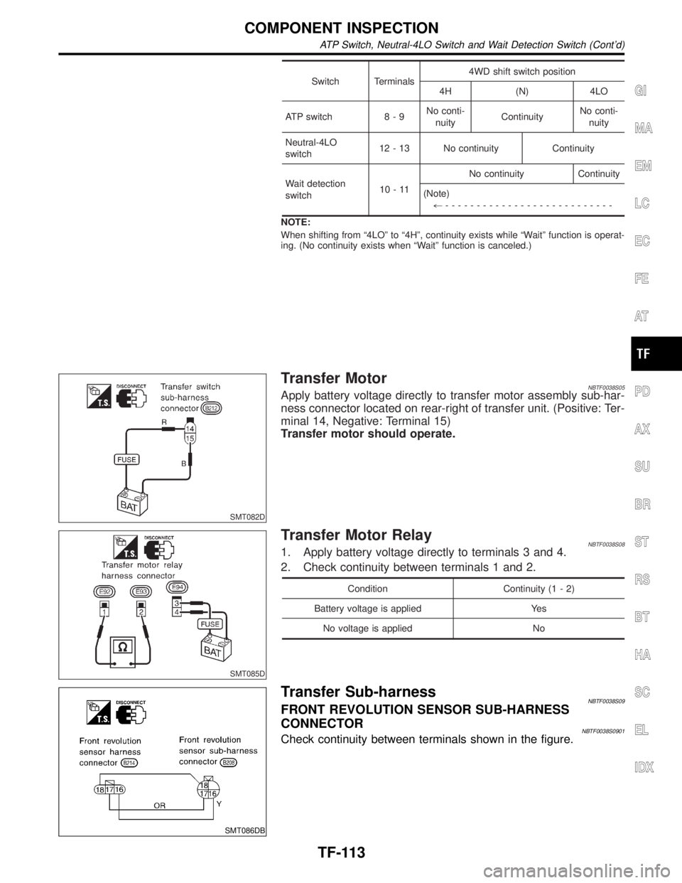
Switch Terminals4WD shift switch position
4H (N) 4LO
ATP switch 8 - 9No conti-
nuityContinuityNo conti-
nuity
Neutral-4LO
switch12 - 13 No continuity Continuity
Wait detection
switch10-11No continuity Continuity
(Note)
+---------------------------
NOTE:
When shifting from ª4LOº to ª4Hº, continuity exists while ªWaitº function is operat-
ing. (No continuity exists when ªWaitº function is canceled.)
SMT082D
Transfer MotorNBTF0038S05Apply battery voltage directly to transfer motor assembly sub-har-
ness connector located on rear-right of transfer unit. (Positive: Ter-
minal 14, Negative: Terminal 15)
Transfer motor should operate.
SMT085D
Transfer Motor RelayNBTF0038S081. Apply battery voltage directly to terminals 3 and 4.
2. Check continuity between terminals 1 and 2.
Condition Continuity (1 - 2)
Battery voltage is applied Yes
No voltage is applied No
SMT086DB
Transfer Sub-harnessNBTF0038S09FRONT REVOLUTION SENSOR SUB-HARNESS
CONNECTOR
NBTF0038S0901Check continuity between terminals shown in the figure.
GI
MA
EM
LC
EC
FE
AT
PD
AX
SU
BR
ST
RS
BT
HA
SC
EL
IDX
COMPONENT INSPECTION
ATP Switch, Neutral-4LO Switch and Wait Detection Switch (Cont'd)
TF-113
Page 2350 of 2395
SMT812D
Actuator & Actuator Position SwitchNBTF0038S11ACTUATORNBTF0038S1101Operation & resistance check
IApply battery voltage directly to actuator assembly.
Operating check Battery positive terminal Battery negative terminal
143
234
Check Approx. 0.2W(When the motor is not operated.)
SMT838D
ACTUATOR POSITION SWITCHNBTF0038S1102Continuity check
Continuity checkBattery positive
terminalBattery negative
terminalContinuity
14 3 1-5
23 4 2-5
GI
MA
EM
LC
EC
FE
AT
PD
AX
SU
BR
ST
RS
BT
HA
SC
EL
IDX
COMPONENT INSPECTION
Actuator & Actuator Position Switch
TF-115