Page 2117 of 2395
SRS006-C
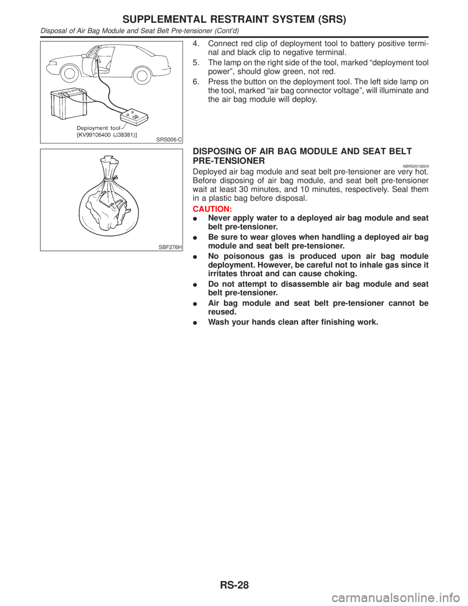
4. Connect red clip of deployment tool to battery positive termi-
nal and black clip to negative terminal.
5. The lamp on the right side of the tool, marked ªdeployment tool
powerº, should glow green, not red.
6. Press the button on the deployment tool. The left side lamp on
the tool, marked ªair bag connector voltageº, will illuminate and
the air bag module will deploy.
SBF276H
DISPOSING OF AIR BAG MODULE AND SEAT BELT
PRE-TENSIONER
NBRS0018S04Deployed air bag module and seat belt pre-tensioner are very hot.
Before disposing of air bag module, and seat belt pre-tensioner
wait at least 30 minutes, and 10 minutes, respectively. Seal them
in a plastic bag before disposal.
CAUTION:
INever apply water to a deployed air bag module and seat
belt pre-tensioner.
IBe sure to wear gloves when handling a deployed air bag
module and seat belt pre-tensioner.
INo poisonous gas is produced upon air bag module
deployment. However, be careful not to inhale gas since it
irritates throat and can cause choking.
IDo not attempt to disassemble air bag module and seat
belt pre-tensioner.
IAir bag module and seat belt pre-tensioner cannot be
reused.
IWash your hands clean after finishing work.
SUPPLEMENTAL RESTRAINT SYSTEM (SRS)
Disposal of Air Bag Module and Seat Belt Pre-tensioner (Cont'd)
RS-28
Page 2155 of 2395
How to Handle BatteryNBSC0003CAUTION:
IIf it becomes necessary to start the engine with a booster
battery and jumper cables, use a 12-volt booster battery.
IAfter connecting battery cables, ensure that they are
tightly clamped to battery terminals for good contact.
INever add distilled water through the hole used to check
specific gravity.
MEL040F
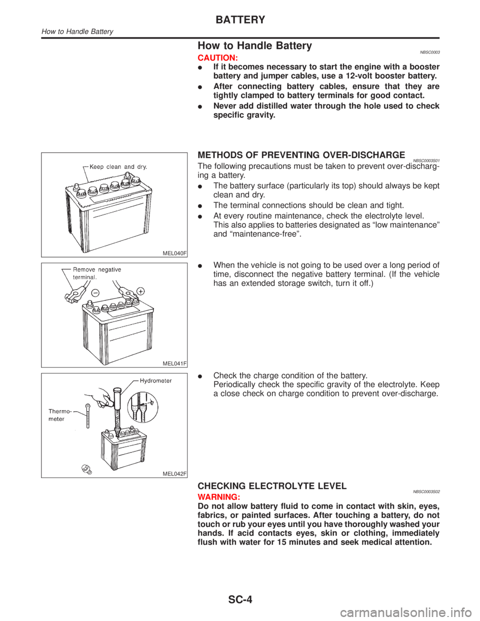
METHODS OF PREVENTING OVER-DISCHARGENBSC0003S01The following precautions must be taken to prevent over-discharg-
ing a battery.
IThe battery surface (particularly its top) should always be kept
clean and dry.
IThe terminal connections should be clean and tight.
IAt every routine maintenance, check the electrolyte level.
This also applies to batteries designated as ªlow maintenanceº
and ªmaintenance-freeº.
MEL041F
IWhen the vehicle is not going to be used over a long period of
time, disconnect the negative battery terminal. (If the vehicle
has an extended storage switch, turn it off.)
MEL042F
ICheck the charge condition of the battery.
Periodically check the specific gravity of the electrolyte. Keep
a close check on charge condition to prevent over-discharge.
CHECKING ELECTROLYTE LEVELNBSC0003S02WARNING:
Do not allow battery fluid to come in contact with skin, eyes,
fabrics, or painted surfaces. After touching a battery, do not
touch or rub your eyes until you have thoroughly washed your
hands. If acid contacts eyes, skin or clothing, immediately
flush with water for 15 minutes and seek medical attention.
BATTERY
How to Handle Battery
SC-4
Page 2158 of 2395
Trouble Diagnoses with
Battery/Starting/Charging System Tester
NBSC0018CAUTION:
When working with batteries, always wear appropriate eye
protection.
NOTE:
ITo ensure a complete and thorough diagnosis, the battery,
starter and alternator test segments must be done as a set
from start to finish.
IIf battery surface charge is detected while testing, the tester
will prompt you to turn on the headlights to remove the surface
charge.
IIf necessary, the tester will prompt you to determine if the bat-
tery temperature is above or below 0ÉC (32ÉF). Choose the
appropriate selection by pressing the up or down arrow button,
then press ªENTERº to make the selection.
SEL404X
1. Turn off all loads on the vehicle electrical system. Clean or
repair as necessary.
2. Visually inspect the battery, battery terminals and cable ends
with ignition switch in ªOFFº position.
NOTE:
The contact surface between the battery terminals, cable ends and
tester leads must be clean for a valid test. A poor connection will
prevent testing and a ªCHECK CONNECTIONº message will
appear during the test procedures. If this occurs, clean the battery
post and terminals, reconnect them and restart the test.
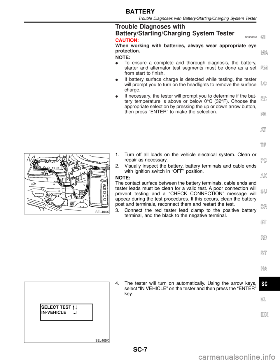
3. Connect the red tester lead clamp to the positive battery
terminal, and the black to the negative terminal.
SEL405X
4. The tester will turn on automatically. Using the arrow keys,
select ªIN VEHICLEº on the tester and then press the ªENTERº
key.
GI
MA
EM
LC
EC
FE
AT
TF
PD
AX
SU
BR
ST
RS
BT
HA
EL
IDX
BATTERY
Trouble Diagnoses with Battery/Starting/Charging System Tester
SC-7
Page 2161 of 2395
System DescriptionNBSC0004Power is supplied at all times
Ito ignition switch terminal 1
Ithrough 40A fusible link (lettere, located in the fuse and fusible link box).
With the ignition switch in the ON or START position, power is supplied through 10A fuse [No. 18, located in
the fuse block (J/B)].
Ito park/neutral position relay terminal 1.
Also, with the ignition switch in the START position, power is supplied
Ifrom ignition switch terminal 5
Ito park/neutral position relay terminal 6.
With the selector lever in the P or N position, ground is supplied
Ito park/neutral position relay terminal 2 through the park/neutral position switch.
Then park/neutral position relay is energized and power is supplied
Ifrom park/neutral position relay terminal 7
Ito terminal 2 of the starter motor windings.
The starter motor plunger closes and provides a closed circuit between the battery and starter motor. The
starter motor is grounded to the engine block. With power and ground supplied, cranking occurs and the engine
starts.
STARTING SYSTEM
System Description
SC-10
Page 2166 of 2395
DIAGNOSTIC PROCEDURE 1NBSC0019S03Check ªBº Terminal CircuitNBSC0019S0301
1 CHECK POWER SUPPLY FOR STARTER MOTOR ªBº TERMINAL
1. Remove the fuel pump fuse.
2. Crank or start the engine (where possible) until the fuel pressure is released.
3. Turn the ignition OFF.
4. Check that the starter motor terminal 1 connection is clean and tight.
5. Check voltage between starter motor terminal 1 and ground using a digital circuit tester.
SEL412X
OK or NG
OK©GO TO 2.
NG©Check harness between the battery and the starter motor for open circuit.
2 CHECK BATTERY CABLE CONNECTION QUALITY (VOLTAGE DROP TEST)
1. Check voltage between starter motor terminal 1 and battery positive terminal using a digital circuit tester.
SEL413X
OK or NG
OK©GO TO 3.
NG©Check harness between the battery and the starter motor for poor continuity.
GI
MA
EM
LC
EC
FE
AT
TF
PD
AX
SU
BR
ST
RS
BT
HA
EL
IDX
STARTING SYSTEM
Trouble Diagnoses with Battery/Starting/Charging System Tester (Cont'd)
SC-15
Page 2167 of 2395
3 CHECK STARTER MOTOR GROUND CIRCUIT (VOLTAGE DROP TEST)
1. Check voltage between starter motor case and battery negative terminal using a digital circuit tester.
SEL414X
OK or NG
OK©Starter motor ªBº terminal circuit is OK. Further inspection necessary. Refer to ªWORK
FLOWº, SC-14.
NG©Check the starter motor case and ground for poor continuity.
STARTING SYSTEM
Trouble Diagnoses with Battery/Starting/Charging System Tester (Cont'd)
SC-16
Page 2168 of 2395
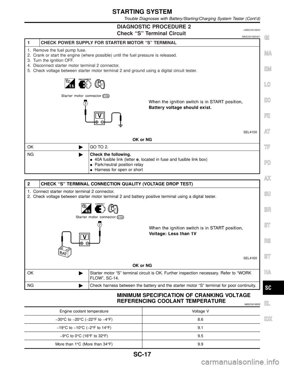
DIAGNOSTIC PROCEDURE 2=NBSC0019S04Check ªSº Terminal CircuitNBSC0019S0401
1 CHECK POWER SUPPLY FOR STARTER MOTOR ªSº TERMINAL
1. Remove the fuel pump fuse.
2. Crank or start the engine (where possible) until the fuel pressure is released.
3. Turn the ignition OFF.
4. Disconnect starter motor terminal 2 connector.
5. Check voltage between starter motor terminal 2 and ground using a digital circuit tester.
SEL415X
OK or NG
OK©GO TO 2.
NG©Check the following.
I40A fusible link (lettere, located in fuse and fusible link box)
IPark/neutral position relay
IHarness for open or short
2 CHECK ªSº TERMINAL CONNECTION QUALITY (VOLTAGE DROP TEST)
1. Connect starter motor terminal 2 connector.
2. Check voltage between starter motor terminal 2 and battery positive terminal using a digital tester.
SEL416X
OK or NG
OK©Starter motor ªSº terminal circuit is OK. Further inspection necessary. Refer to ªWORK
FLOWº, SC-14.
NG©Check harness between the battery and the starter motor ªSº terminal for poor continuity.
MINIMUM SPECIFICATION OF CRANKING VOLTAGE
REFERENCING COOLANT TEMPERATURE
NBSC0019S05
Engine coolant temperature Voltage V
þ30ÉC to þ20ÉC (þ22ÉF to þ4ÉF) 8.6
þ19ÉC to þ10ÉC (þ2ÉF to 14ÉF) 9.1
þ9ÉC to 0ÉC (16ÉF to 32ÉF) 9.5
More than 1ÉC (More than 34ÉF) 9.9
GI
MA
EM
LC
EC
FE
AT
TF
PD
AX
SU
BR
ST
RS
BT
HA
EL
IDX
STARTING SYSTEM
Trouble Diagnoses with Battery/Starting/Charging System Tester (Cont'd)
SC-17
Page 2170 of 2395
System DescriptionNBSC0009The alternator provides DC voltage to operate the vehicle's electrical system and to keep the battery charged.
The voltage output is controlled by the IC regulator.
Power is supplied at all times to alternator terminal S through:
I120A fusible link (lettera, located in the fuse and fusible link box), and
I7.5A fuse (No. 65, located in the fuse and fusible link box).
Terminal B supplies power to charge the battery and operate the vehicle's electrical system. Output voltage
is controlled by the IC regulator at terminal S detecting the input voltage. The charging circuit is protected by
the 120A fusible link.
Terminal E of the alternator supplies ground through body ground E101.
With the ignition switch in the ON or START position, power is supplied
Ithrough 10A fuse [No. 8, located in the fuse block (J/B)]
Ito combination meter terminal 12 for the charge warning lamp.
Ground is supplied to terminal 43 of the combination meter through terminal L of the alternator. With power
and ground supplied, the charge warning lamp will illuminate. When the alternator is providing sufficient volt-
age with the engine running, the ground is opened and the charge warning lamp will go off.
If the charge warning lamp illuminates with the engine running, a fault is indicated.GI
MA
EM
LC
EC
FE
AT
TF
PD
AX
SU
BR
ST
RS
BT
HA
EL
IDX
CHARGING SYSTEM
System Description
SC-19