Page 1314 of 2395
Trouble DiagnosesNBEL0055SYMPTOM CHARTNBEL0055S01
REFERENCE PAGE (EL- ) 129 131 133 134 135
SYMPTOM
POWER SUPPLY AND GROUND CIRCUIT CHECK
LIGHTING SWITCH INPUT SIGNAL CHECK
KEY SWITCH (INSERT) CHECK
SEAT BELT BUCKLE SWITCH CHECK
DRIVER SIDE DOOR SWITCH CHECK
Light warning chime does not acti-
vate.XX X
Ignition key warning chime does not
activate.XXX
Seat belt warning chime does not
activate.XX
All warning chimes do not activate. X
SEL301X
POWER SUPPLY AND GROUND CIRCUIT CHECKNBEL0055S02Power Supply Circuit CheckNBEL0055S0201
Terminals Ignition switch position
(+) (þ) OFF ACC ON
10 GroundBattery
voltageBattery
voltageBattery
voltage
33 Ground 0V 0VBattery
voltage
GI
MA
EM
LC
EC
FE
AT
TF
PD
AX
SU
BR
ST
RS
BT
HA
SC
IDX
WARNING CHIME
Trouble Diagnoses
EL-129
Page 1316 of 2395
LIGHTING SWITCH INPUT SIGNAL CHECK=NBEL0055S03
1 CHECK LIGHTING SWITCH INPUT SIGNAL
Check voltage between smart entrance control unit terminal 34 and ground.
SEL377X
OK or NG
OK©Lighting switch is OK.
NG©GO TO 2.
2 CHECK FUSE
Is 10A fuse (No. 61, located in the fuse and fusible link box) OK?
OK or NG
OK©GO TO 3.
NG©Replace fuse.
3 CHECK TAIL LAMP RELAY CIRCUIT
Check voltage between headlamp battery saver control unit terminal 6, 14 and ground.
SEL378X
OK or NG
OK©Check the following.
ITail lamp relay
IHarness for open or short between smart entrance control unit and tail lamp relay.
NG©GO TO 4.
GI
MA
EM
LC
EC
FE
AT
TF
PD
AX
SU
BR
ST
RS
BT
HA
SC
IDX
WARNING CHIME
Trouble Diagnoses (Cont'd)
EL-131
Page 1317 of 2395
4 CHECK TAIL LAMP SWITCH GROUND CIRCUIT
1. Disconnect headlamp battery saver control unit connector.
2. Check continuity between headlamp battery saver control unit terminal 5, 13 and ground.
SEL379X
OK or NG
OK©Check headlamp battery saver control unit. Refer to EL-42.
NG©Check the following.
ILighting switch
IHarness for open or short between headlamp battery saver control unit terminal 5, 13
and lighting switch terminal 11
IHarness between lighting switch terminal 5 and ground
WARNING CHIME
Trouble Diagnoses (Cont'd)
EL-132
Page 1330 of 2395

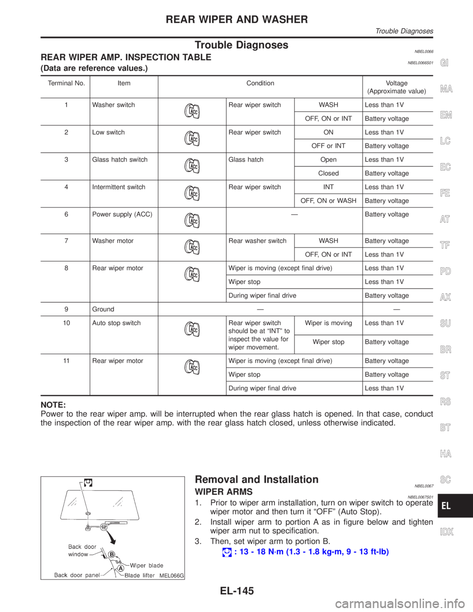
Trouble DiagnosesNBEL0066REAR WIPER AMP. INSPECTION TABLENBEL0066S01(Data are reference values.)
Terminal No. Item Condition Voltage
(Approximate value)
1 Washer switch
Rear wiper switch WASH Less than 1V
OFF, ON or INT Battery voltage
2 Low switch
Rear wiper switch ON Less than 1V
OFF or INT Battery voltage
3 Glass hatch switch
Glass hatch Open Less than 1V
Closed Battery voltage
4 Intermittent switch
Rear wiper switch INT Less than 1V
OFF, ON or WASH Battery voltage
6 Power supply (ACC)
Ð Battery voltage
7 Washer motor
Rear washer switch WASH Battery voltage
OFF, ON or INT Less than 1V
8 Rear wiper motor
Wiper is moving (except final drive) Less than 1V
Wiper stop Less than 1V
During wiper final drive Battery voltage
9 Ground Ð Ð
10 Auto stop switch
Rear wiper switch
should be at ªINTº to
inspect the value for
wiper movement.Wiper is moving Less than 1V
Wiper stop Battery voltage
11 Rear wiper motor
Wiper is moving (except final drive) Battery voltage
Wiper stop Battery voltage
During wiper final drive Less than 1V
NOTE:
Power to the rear wiper amp. will be interrupted when the rear glass hatch is opened. In that case, conduct
the inspection of the rear wiper amp. with the rear glass hatch closed, unless otherwise indicated.
MEL066G
Removal and InstallationNBEL0067WIPER ARMSNBEL0067S011. Prior to wiper arm installation, turn on wiper switch to operate
wiper motor and then turn it ªOFFº (Auto Stop).
2. Install wiper arm to portion A as in figure below and tighten
wiper arm nut to specification.
3. Then, set wiper arm to portion B.
: 13 - 18 N´m (1.3 - 1.8 kg-m,9-13ft-lb)
GI
MA
EM
LC
EC
FE
AT
TF
PD
AX
SU
BR
ST
RS
BT
HA
SC
IDX
REAR WIPER AND WASHER
Trouble Diagnoses
EL-145
Page 1351 of 2395

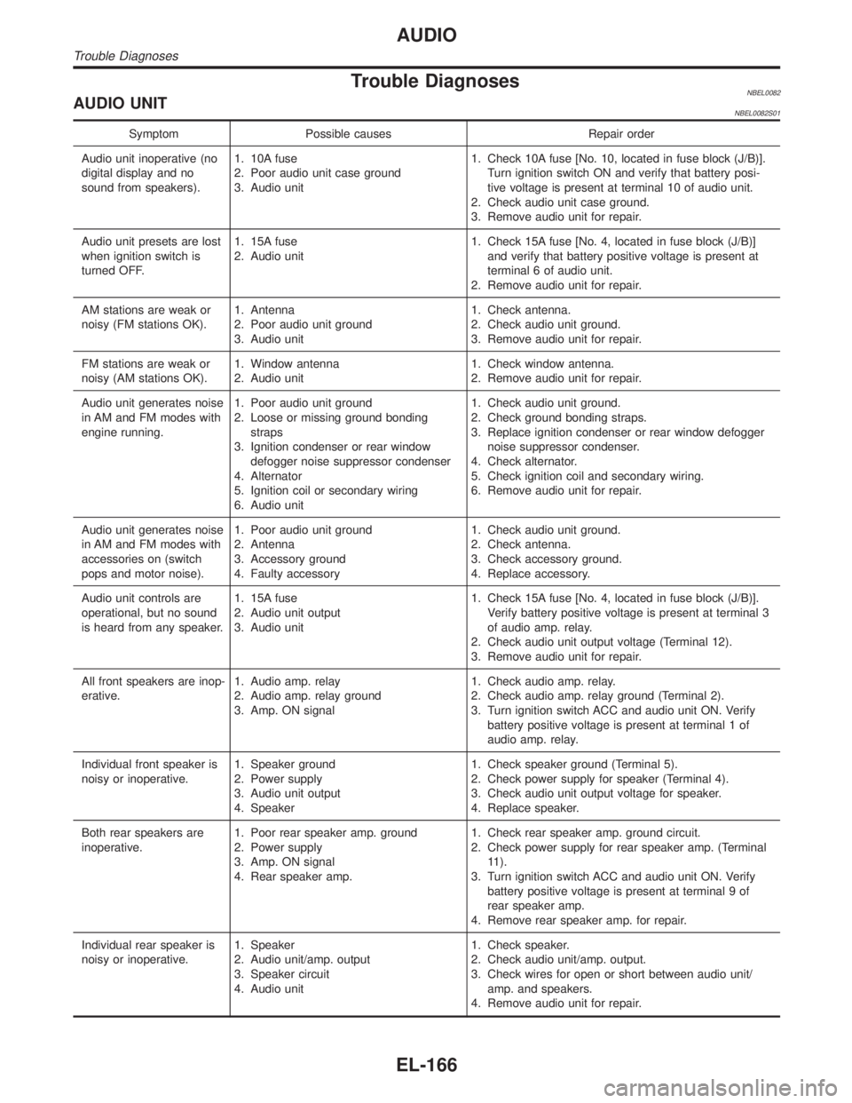
Trouble DiagnosesNBEL0082AUDIO UNITNBEL0082S01
Symptom Possible causes Repair order
Audio unit inoperative (no
digital display and no
sound from speakers).1. 10A fuse
2. Poor audio unit case ground
3. Audio unit1. Check 10A fuse [No. 10, located in fuse block (J/B)].
Turn ignition switch ON and verify that battery posi-
tive voltage is present at terminal 10 of audio unit.
2. Check audio unit case ground.
3. Remove audio unit for repair.
Audio unit presets are lost
when ignition switch is
turned OFF.1. 15A fuse
2. Audio unit1. Check 15A fuse [No. 4, located in fuse block (J/B)]
and verify that battery positive voltage is present at
terminal 6 of audio unit.
2. Remove audio unit for repair.
AM stations are weak or
noisy (FM stations OK).1. Antenna
2. Poor audio unit ground
3. Audio unit1. Check antenna.
2. Check audio unit ground.
3. Remove audio unit for repair.
FM stations are weak or
noisy (AM stations OK).1. Window antenna
2. Audio unit1. Check window antenna.
2. Remove audio unit for repair.
Audio unit generates noise
in AM and FM modes with
engine running.1. Poor audio unit ground
2. Loose or missing ground bonding
straps
3. Ignition condenser or rear window
defogger noise suppressor condenser
4. Alternator
5. Ignition coil or secondary wiring
6. Audio unit1. Check audio unit ground.
2. Check ground bonding straps.
3. Replace ignition condenser or rear window defogger
noise suppressor condenser.
4. Check alternator.
5. Check ignition coil and secondary wiring.
6. Remove audio unit for repair.
Audio unit generates noise
in AM and FM modes with
accessories on (switch
pops and motor noise).1. Poor audio unit ground
2. Antenna
3. Accessory ground
4. Faulty accessory1. Check audio unit ground.
2. Check antenna.
3. Check accessory ground.
4. Replace accessory.
Audio unit controls are
operational, but no sound
is heard from any speaker.1. 15A fuse
2. Audio unit output
3. Audio unit1. Check 15A fuse [No. 4, located in fuse block (J/B)].
Verify battery positive voltage is present at terminal 3
of audio amp. relay.
2. Check audio unit output voltage (Terminal 12).
3. Remove audio unit for repair.
All front speakers are inop-
erative.1. Audio amp. relay
2. Audio amp. relay ground
3. Amp. ON signal1. Check audio amp. relay.
2. Check audio amp. relay ground (Terminal 2).
3. Turn ignition switch ACC and audio unit ON. Verify
battery positive voltage is present at terminal 1 of
audio amp. relay.
Individual front speaker is
noisy or inoperative.1. Speaker ground
2. Power supply
3. Audio unit output
4. Speaker1. Check speaker ground (Terminal 5).
2. Check power supply for speaker (Terminal 4).
3. Check audio unit output voltage for speaker.
4. Replace speaker.
Both rear speakers are
inoperative.1. Poor rear speaker amp. ground
2. Power supply
3. Amp. ON signal
4. Rear speaker amp.1. Check rear speaker amp. ground circuit.
2. Check power supply for rear speaker amp. (Terminal
11).
3. Turn ignition switch ACC and audio unit ON. Verify
battery positive voltage is present at terminal 9 of
rear speaker amp.
4. Remove rear speaker amp. for repair.
Individual rear speaker is
noisy or inoperative.1. Speaker
2. Audio unit/amp. output
3. Speaker circuit
4. Audio unit1. Check speaker.
2. Check audio unit/amp. output.
3. Check wires for open or short between audio unit/
amp. and speakers.
4. Remove audio unit for repair.
AUDIO
Trouble Diagnoses
EL-166
Page 1354 of 2395
System DescriptionNBEL0084Power is supplied at all times
Ithrough 7.5A fuse [No. 24, located in the fuse block (J/B)]
Ito power antenna terminal 6.
Ground is supplied to the power antenna terminal 2 through body grounds M4, M66 and M147.
When the audio unit is turned to the ON position, battery positive voltage is supplied
Ithrough audio unit terminal 5
Ito power antenna terminal 4.
The antenna raises and is held in the extended position.
When the audio unit is turned to the OFF position, battery positive voltage is interrupted
Ifrom audio unit terminal 5
Ito power antenna terminal 4.
The antenna retracts.GI
MA
EM
LC
EC
FE
AT
TF
PD
AX
SU
BR
ST
RS
BT
HA
SC
IDX
AUDIO ANTENNA
System Description
EL-169
Page 1356 of 2395
Trouble DiagnosesNBEL0086POWER ANTENNANBEL0086S01
Symptom Possible causes Repair order
Power antenna does not
operate.1. 7.5A fuse
2. Audio unit signal
3. Grounds M4, M66 and M1471. Check 7.5A fuse [No. 24, located in fuse block (J/B)].
Verify that battery positive voltage is present at termi-
nal 6 of power antenna.
2. Turn ignition switch and audio unit ON. Verify that
battery positive voltage is present at terminal 4 of
power antenna.
3. Check grounds M4, M66 and M147.
Location of AntennaNBEL0087
YEL067K
MEL036G
Antenna Rod ReplacementNBEL0088REMOVALNBEL0088S011. Remove antenna nut and antenna base.
GI
MA
EM
LC
EC
FE
AT
TF
PD
AX
SU
BR
ST
RS
BT
HA
SC
IDX
AUDIO ANTENNA
Trouble Diagnoses
EL-171
Page 1361 of 2395

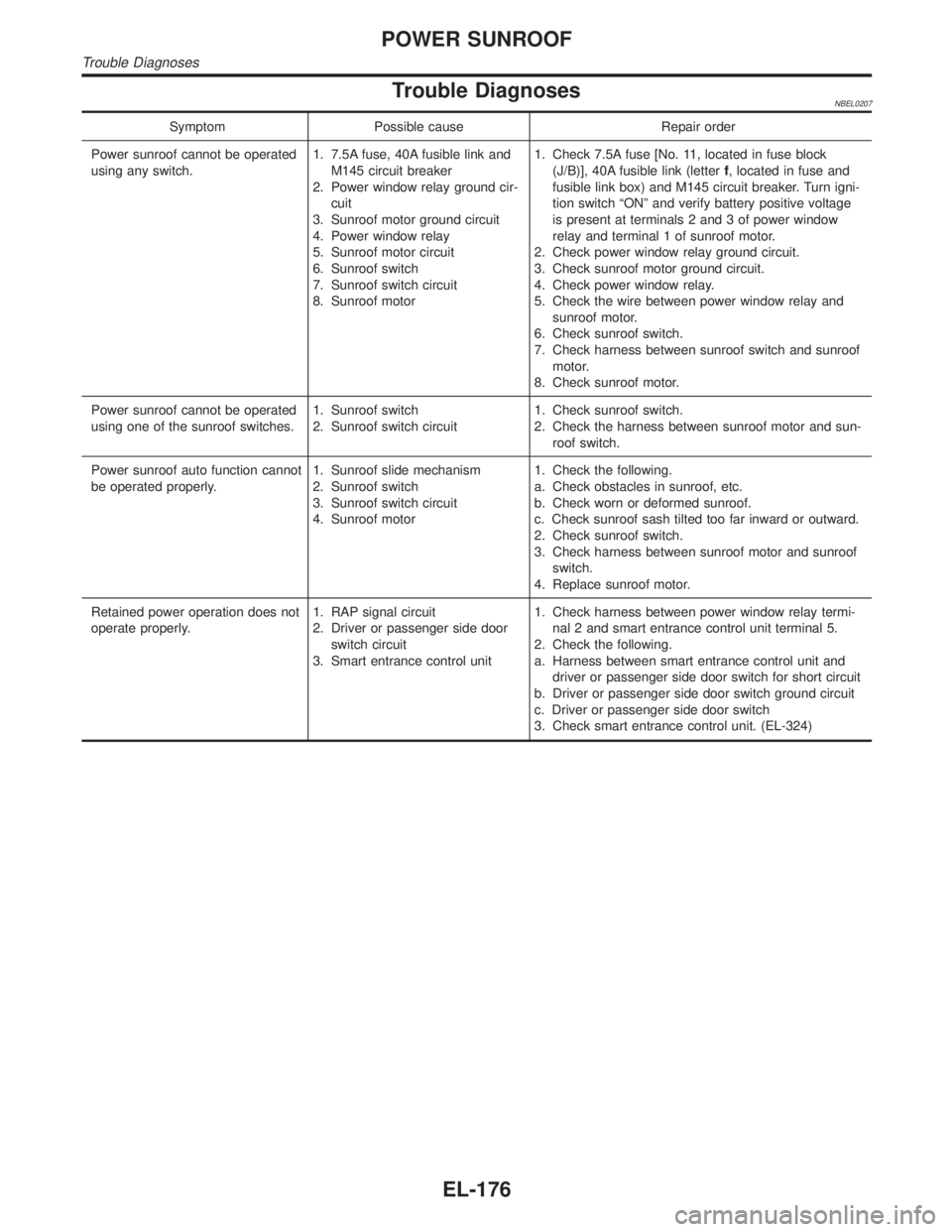
Trouble DiagnosesNBEL0207
Symptom Possible cause Repair order
Power sunroof cannot be operated
using any switch.1. 7.5A fuse, 40A fusible link and
M145 circuit breaker
2. Power window relay ground cir-
cuit
3. Sunroof motor ground circuit
4. Power window relay
5. Sunroof motor circuit
6. Sunroof switch
7. Sunroof switch circuit
8. Sunroof motor1. Check 7.5A fuse [No. 11, located in fuse block
(J/B)], 40A fusible link (letterf, located in fuse and
fusible link box) and M145 circuit breaker. Turn igni-
tion switch ªONº and verify battery positive voltage
is present at terminals 2 and 3 of power window
relay and terminal 1 of sunroof motor.
2. Check power window relay ground circuit.
3. Check sunroof motor ground circuit.
4. Check power window relay.
5. Check the wire between power window relay and
sunroof motor.
6. Check sunroof switch.
7. Check harness between sunroof switch and sunroof
motor.
8. Check sunroof motor.
Power sunroof cannot be operated
using one of the sunroof switches.1. Sunroof switch
2. Sunroof switch circuit1. Check sunroof switch.
2. Check the harness between sunroof motor and sun-
roof switch.
Power sunroof auto function cannot
be operated properly.1. Sunroof slide mechanism
2. Sunroof switch
3. Sunroof switch circuit
4. Sunroof motor1. Check the following.
a. Check obstacles in sunroof, etc.
b. Check worn or deformed sunroof.
c. Check sunroof sash tilted too far inward or outward.
2. Check sunroof switch.
3. Check harness between sunroof motor and sunroof
switch.
4. Replace sunroof motor.
Retained power operation does not
operate properly.1. RAP signal circuit
2. Driver or passenger side door
switch circuit
3. Smart entrance control unit1. Check harness between power window relay termi-
nal 2 and smart entrance control unit terminal 5.
2. Check the following.
a. Harness between smart entrance control unit and
driver or passenger side door switch for short circuit
b. Driver or passenger side door switch ground circuit
c. Driver or passenger side door switch
3. Check smart entrance control unit. (EL-324)
POWER SUNROOF
Trouble Diagnoses
EL-176