2001 INFINITI QX4 Battery terminal
[x] Cancel search: Battery terminalPage 1778 of 2395
![INFINITI QX4 2001 Factory Service Manual MGI035A
Input-output voltage chart
Pin No. Item ConditionVoltage
value [V]In case of high resistance such as single strand [V]
*
1 Lamp Switch ON Approx. 0 Battery voltage (Inoperative lamp)
Switch OF INFINITI QX4 2001 Factory Service Manual MGI035A
Input-output voltage chart
Pin No. Item ConditionVoltage
value [V]In case of high resistance such as single strand [V]
*
1 Lamp Switch ON Approx. 0 Battery voltage (Inoperative lamp)
Switch OF](/manual-img/42/57027/w960_57027-1777.png)
MGI035A
Input-output voltage chart
Pin No. Item ConditionVoltage
value [V]In case of high resistance such as single strand [V]
*
1 Lamp Switch ON Approx. 0 Battery voltage (Inoperative lamp)
Switch OFF Battery voltage Battery voltage
2 Switch Switch ON Approx. 0 Higher than 0 Approx. 4 (Example)
Switch OFF Approx. 5 Approx. 5
The voltage value is based on the body ground.
* : If high resistance exists in the switch side circuit (caused by a single strand), terminal 2 does not detect approx. 0V. Control unit
does not detect the switch is ON even if the switch does not turn ON. Therefore, the control unit does not control ground to light up the
lamp.
MA
EM
LC
EC
FE
AT
TF
PD
AX
SU
BR
ST
RS
BT
HA
SC
EL
IDX
HOW TO PERFORM EFFICIENT DIAGNOSIS FOR AN ELECTRICAL INCIDENT
Circuit Inspection (Cont'd)
GI-33
Page 1811 of 2395
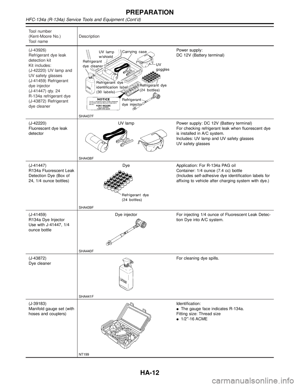
Tool number
(Kent-Moore No.)
Tool nameDescription
(J-43926)
Refrigerant dye leak
detection kit
Kit includes:
(J-42220) UV lamp and
UV safety glasses
(J-41459) Refrigerant
dye injector
(J-41447) qty. 24
R-134a refrigerant dye
(J-43872) Refrigerant
dye cleaner
SHA437F
Power supply:
DC 12V (Battery terminal)
(J-42220)
Fluorescent dye leak
detectorUV lamp
SHA438F
Power supply: DC 12V (Battery terminal)
For checking refrigerant leak when fluorescent dye
is installed in A/C system.
Includes: UV lamp and UV safety glasses
UV safety glasses
(J-41447)
R134a Fluorescent Leak
Detection Dye (Box of
24, 1/4 ounce bottles)Dye
SHA439F
Application: For R-134a PAG oil
Container: 1/4 ounce (7.4 cc) bottle
(Includes self-adhesive dye identification labels for
affixing to vehicle after charging system with dye.)
(J-41459)
R134a Dye Injector
Use with J-41447, 1/4
ounce bottleDye injector
SHA440F
For injecting 1/4 ounce of Fluorescent Leak Detec-
tion Dye into A/C system.
(J-43872)
Dye cleaner
SHA441F
For cleaning dye spills.
(J-39183)
Manifold gauge set (with
hoses and couplers)
NT199
Identification:
IThe gauge face indicates R-134a.
Fitting size: Thread size
I1/2²-16 ACME
PREPARATION
HFC-134a (R-134a) Service Tools and Equipment (Cont'd)
HA-12
Page 1840 of 2395
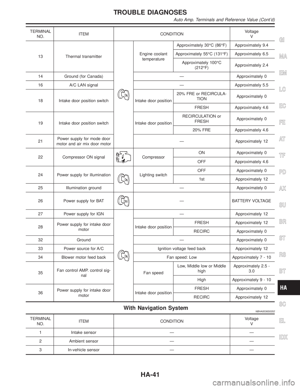
TERMINAL
NO.ITEM CONDITIONVoltage
V
13 Thermal transmitter
Engine coolant
temperatureApproximately 30ÉC (86ÉF) Approximately 9.4
Approximately 55ÉC (131ÉF) Approximately 6.5
Approximately 100ÉC
(212ÉF)Approximately 2.4
14 Ground (for Canada) Ð Approximately 0
16 A/C LAN signal Ð Approximately 5.5
18 Intake door position switch Intake door position20% FRE or RECIRCULA-
TIONApproximately 0
FRESH Approximately 4.6
19 Intake door position switch Intake door positionRECIRCULATION or
FRESHApproximately 0
20% FRE Approximately 4.6
21Power supply for mode door
motor and air mix door motorÐ Approximately 12
22 Compressor ON signal
CompressorON Approximately 0
OFF Approximately 4.6
24 Power supply for illumination
Lighting switchOFF Approximately 0
1st Approximately 12
25 Illumination ground Ð Approximately 0
26 Power supply for BAT
Ð BATTERY VOLTAGE
27 Power supply for IGN
Ð Approximately 12
28Power supply for intake door
motorIntake door positionFRESH Approximately 12
RECIRC Approximately 0
32 Ground Ð Approximately 0
33 Power source for A/C Ignition voltage feed back Approximately 12
34 Blower motor feed back Fan speed: Low Approximately7-10
35Fan control AMP. control sig-
nalFan speedLow, Middle low or Middle
highApproximately 2.5 -
3.0
High Approximately9-10
36Power supply for intake door
motorIntake door positionFRESH Approximately 0
RECIRC Approximately 12
With Navigation SystemNBHA0036S0202
TERMINAL
NO.ITEM CONDITIONVoltage
V
1 Intake sensor Ð Ð
2 Ambient sensor Ð Ð
3 In-vehicle sensor Ð Ð
GI
MA
EM
LC
EC
FE
AT
TF
PD
AX
SU
BR
ST
RS
BT
SC
EL
IDX
TROUBLE DIAGNOSES
Auto Amp. Terminals and Reference Value (Cont'd)
HA-41
Page 1841 of 2395
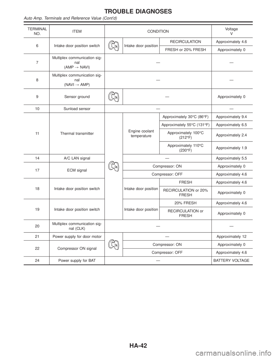
TERMINAL
NO.ITEM CONDITIONVoltage
V
6 Intake door position switch
Intake door positionRECIRCULATION Approximately 4.6
FRESH or 20% FRESH Approximately 0
7Multiplex communication sig-
nal
(AMP,NAVI)ÐÐ
8Multiplex communication sig-
nal
(NAVI,AMP)ÐÐ
9 Sensor ground
Ð Approximately 0
10 Sunload sensor Ð Ð
11 Thermal transmitter
Engine coolant
temperatureApproximately 30ÉC (86ÉF) Approximately 9.4
Approximately 55ÉC (131ÉF) Approximately 6.5
Approximately 100ÉC
(212ÉF)Approximately 2.4
Approximately 110ÉC
(230ÉF)Approximately 1.9
14 A/C LAN signal Ð Approximately 5.5
17 ECM signalCompressor: ON Approximately 0
Compressor: OFF Approximately 4.6
18 Intake door position switch Intake door positionFRESH Approximately 4.6
RECIRCULATION or 20%
FRESHApproximately 0
19 Intake door position switch Intake door position20% FRESH Approximately 4.6
RECIRCULATION or
FRESHApproximately 0
20Multiplex communication sig-
nal (CLK)ÐÐ
21 Power supply for door motor
Ð Approximately 12
22 Compressor ON signalCompressor: ON Approximately 0
Compressor: OFF Approximately 4.6
24 Power supply for BAT Ð BATTERY VOLTAGE
TROUBLE DIAGNOSES
Auto Amp. Terminals and Reference Value (Cont'd)
HA-42
Page 2112 of 2395
IWhen deploying the air bag module and seat belt pre-
tensioner, stand at least 5 m (16 ft) away from the deployment
component.
IWhen deploying air bag module and seat belt pre-tensioner, a
fairly loud noise is made, followed by smoke being released.
The smoke is not poisonous, however, be careful not to inhale
smoke since it irritates the throat and can cause choking.
IAlways activate one air bag module at a time.
IDue to heat, leave air bag module unattended for more than
30 minutes after deployment. Also leave seat belt pre-ten-
sioner unattended for move than 10 minutes after deployment.
IBe sure to wear gloves when handling a deployed air bag
module and seat belt pre-tensioner.
INever apply water to the deployed air bag module and seat
belt pre-tensioner.
IWash your hands clean after finishing work.
IPlace the vehicle outdoors with an open space of at least 6 m
(20 ft) on all sides when deploying air bag module and seat belt
pre-tensioner while mounted in vehicle.
IUse a voltmeter to make sure the vehicle battery is fully
charged.
IDo not dispose of the air bag module and seat belt pre-ten-
sioner un-deployed.
SRS019
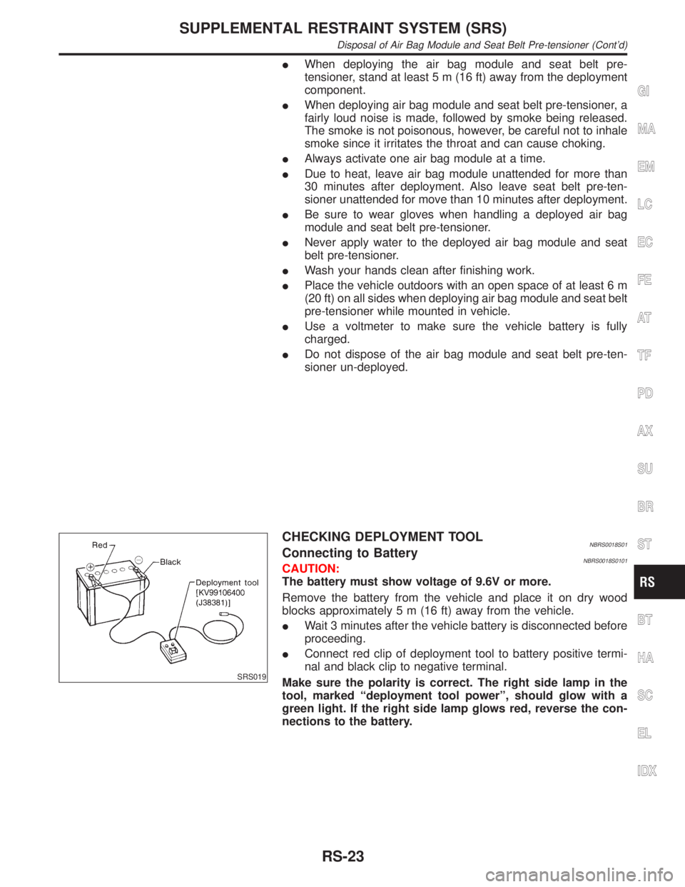
CHECKING DEPLOYMENT TOOLNBRS0018S01Connecting to BatteryNBRS0018S0101CAUTION:
The battery must show voltage of 9.6V or more.
Remove the battery from the vehicle and place it on dry wood
blocks approximately 5 m (16 ft) away from the vehicle.
IWait 3 minutes after the vehicle battery is disconnected before
proceeding.
IConnect red clip of deployment tool to battery positive termi-
nal and black clip to negative terminal.
Make sure the polarity is correct. The right side lamp in the
tool, marked ªdeployment tool powerº, should glow with a
green light. If the right side lamp glows red, reverse the con-
nections to the battery.
GI
MA
EM
LC
EC
FE
AT
TF
PD
AX
SU
BR
ST
BT
HA
SC
EL
IDX
SUPPLEMENTAL RESTRAINT SYSTEM (SRS)
Disposal of Air Bag Module and Seat Belt Pre-tensioner (Cont'd)
RS-23
Page 2114 of 2395
SRS020-B
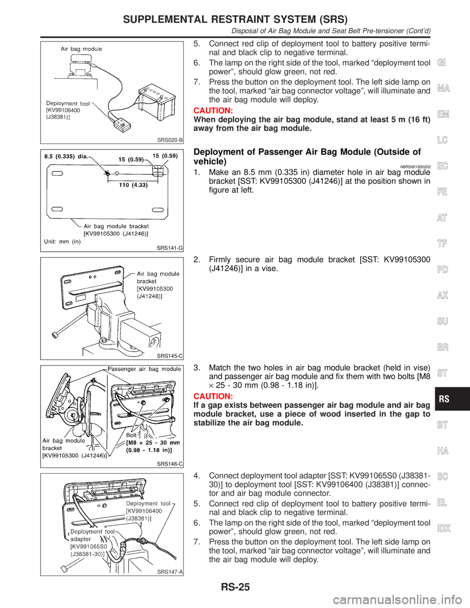
5. Connect red clip of deployment tool to battery positive termi-
nal and black clip to negative terminal.
6. The lamp on the right side of the tool, marked ªdeployment tool
powerº, should glow green, not red.
7. Press the button on the deployment tool. The left side lamp on
the tool, marked ªair bag connector voltageº, will illuminate and
the air bag module will deploy.
CAUTION:
When deploying the air bag module, stand at least 5 m (16 ft)
away from the air bag module.
SRS141-G
Deployment of Passenger Air Bag Module (Outside of
vehicle)
NBRS0018S02021. Make an 8.5 mm (0.335 in) diameter hole in air bag module
bracket [SST: KV99105300 (J41246)] at the position shown in
figure at left.
SRS145-C
2. Firmly secure air bag module bracket [SST: KV99105300
(J41246)] in a vise.
SRS146-C
3. Match the two holes in air bag module bracket (held in vise)
and passenger air bag module and fix them with two bolts [M8
´25 - 30 mm (0.98 - 1.18 in)].
CAUTION:
If a gap exists between passenger air bag module and air bag
module bracket, use a piece of wood inserted in the gap to
stabilize the air bag module.
SRS147-A
4. Connect deployment tool adapter [SST: KV991065S0 (J38381-
30)] to deployment tool [SST: KV99106400 (J38381)] connec-
tor and air bag module connector.
5. Connect red clip of deployment tool to battery positive termi-
nal and black clip to negative terminal.
6. The lamp on the right side of the tool, marked ªdeployment tool
powerº, should glow green, not red.
7. Press the button on the deployment tool. The left side lamp on
the tool, marked ªair bag connector voltageº, will illuminate and
the air bag module will deploy.
GI
MA
EM
LC
EC
FE
AT
TF
PD
AX
SU
BR
ST
BT
HA
SC
EL
IDX
SUPPLEMENTAL RESTRAINT SYSTEM (SRS)
Disposal of Air Bag Module and Seat Belt Pre-tensioner (Cont'd)
RS-25
Page 2115 of 2395
SRS020-B
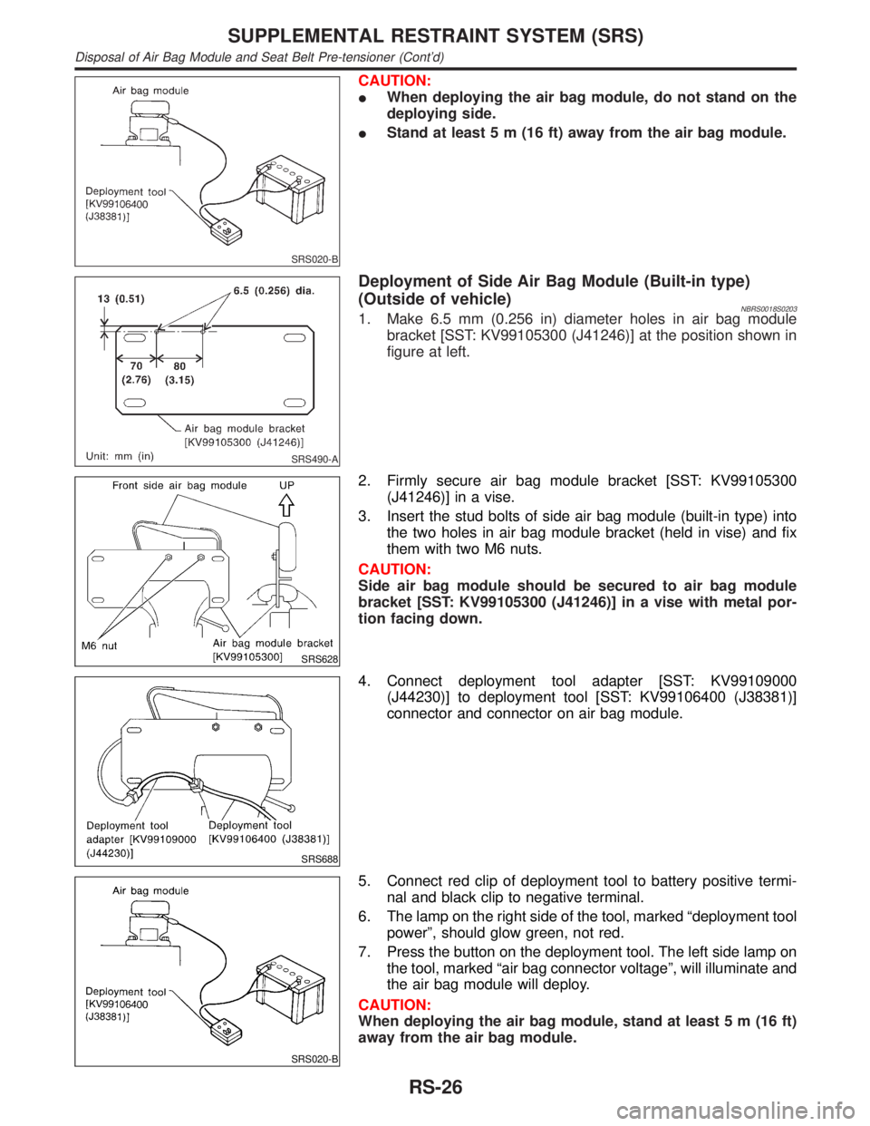
CAUTION:
IWhen deploying the air bag module, do not stand on the
deploying side.
IStand at least 5 m (16 ft) away from the air bag module.
SRS490-A
Deployment of Side Air Bag Module (Built-in type)
(Outside of vehicle)
NBRS0018S02031. Make 6.5 mm (0.256 in) diameter holes in air bag module
bracket [SST: KV99105300 (J41246)] at the position shown in
figure at left.
SRS628
2. Firmly secure air bag module bracket [SST: KV99105300
(J41246)] in a vise.
3. Insert the stud bolts of side air bag module (built-in type) into
the two holes in air bag module bracket (held in vise) and fix
them with two M6 nuts.
CAUTION:
Side air bag module should be secured to air bag module
bracket [SST: KV99105300 (J41246)] in a vise with metal por-
tion facing down.
SRS688
4. Connect deployment tool adapter [SST: KV99109000
(J44230)] to deployment tool [SST: KV99106400 (J38381)]
connector and connector on air bag module.
SRS020-B
5. Connect red clip of deployment tool to battery positive termi-
nal and black clip to negative terminal.
6. The lamp on the right side of the tool, marked ªdeployment tool
powerº, should glow green, not red.
7. Press the button on the deployment tool. The left side lamp on
the tool, marked ªair bag connector voltageº, will illuminate and
the air bag module will deploy.
CAUTION:
When deploying the air bag module, stand at least 5 m (16 ft)
away from the air bag module.
SUPPLEMENTAL RESTRAINT SYSTEM (SRS)
Disposal of Air Bag Module and Seat Belt Pre-tensioner (Cont'd)
RS-26
Page 2116 of 2395
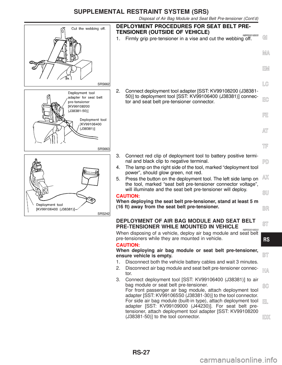
SRS662
DEPLOYMENT PROCEDURES FOR SEAT BELT PRE-
TENSIONER (OUTSIDE OF VEHICLE)
NBRS0018S051. Firmly grip pre-tensioner in a vise and cut the webbing off.
SRS663
2. Connect deployment tool adapter [SST: KV99108200 (J38381-
50)] to deployment tool [SST: KV99106400 (J38381)] connec-
tor and seat belt pre-tensioner connector.
SRS242
3. Connect red clip of deployment tool to battery positive termi-
nal and black clip to negative terminal.
4. The lamp on the right side of the tool, marked ªdeployment tool
powerº, should glow green, not red.
5. Press the button on the deployment tool. The left side lamp on
the tool, marked ªseat belt pre-tensioner connector voltageº,
will illuminate and the seat belt pre-tensioner will deploy.
CAUTION:
When deploying the seat belt pre-tensioner, stand at least 5 m
(16 ft) away from the seat belt pre-tensioner.
DEPLOYMENT OF AIR BAG MODULE AND SEAT BELT
PRE-TENSIONER WHILE MOUNTED IN VEHICLE
NBRS0018S03When disposing of a vehicle, deploy air bag module and seat belt
pre-tensioners while they are mounted in vehicle.
CAUTION:
When deploying air bag module or seat belt pre-tensioner,
ensure vehicle is empty.
1. Disconnect both the vehicle battery cables and wait 3 minutes.
2. Disconnect air bag module and seat belt pre-tensioner connec-
tor.
3. Connect deployment tool [SST: KV99106400 (J38381)] to air
bag module or seat belt pre-tensioner.
For front passenger air bag module, attach deployment tool
adapter [SST: KV991065S0 (J38381-30)] to the tool connector.
For side air bag module (built-in type), attach deployment tool
adapter [SST: KV99109000 (J44230)]. For seat belt pre-
tensioner, attach deployment tool adapter [SST: KV99108200
(J38381-50)] to the tool connector.
GI
MA
EM
LC
EC
FE
AT
TF
PD
AX
SU
BR
ST
BT
HA
SC
EL
IDX
SUPPLEMENTAL RESTRAINT SYSTEM (SRS)
Disposal of Air Bag Module and Seat Belt Pre-tensioner (Cont'd)
RS-27