Page 1108 of 2395
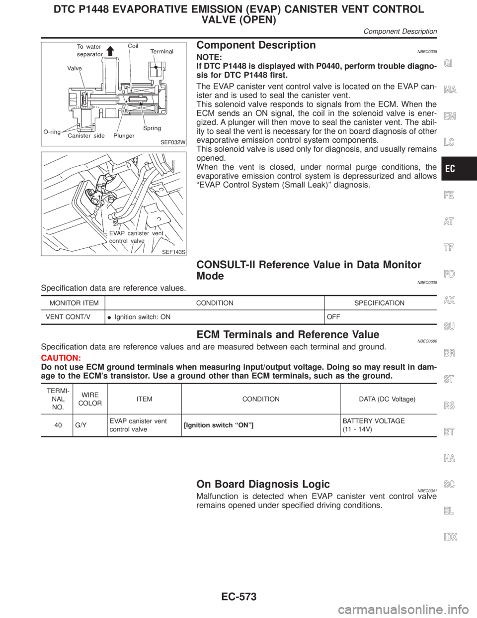
SEF032W
SEF143S
Component DescriptionNBEC0338NOTE:
If DTC P1448 is displayed with P0440, perform trouble diagno-
sis for DTC P1448 first.
The EVAP canister vent control valve is located on the EVAP can-
ister and is used to seal the canister vent.
This solenoid valve responds to signals from the ECM. When the
ECM sends an ON signal, the coil in the solenoid valve is ener-
gized. A plunger will then move to seal the canister vent. The abil-
ity to seal the vent is necessary for the on board diagnosis of other
evaporative emission control system components.
This solenoid valve is used only for diagnosis, and usually remains
opened.
When the vent is closed, under normal purge conditions, the
evaporative emission control system is depressurized and allows
ªEVAP Control System (Small Leak)º diagnosis.
CONSULT-II Reference Value in Data Monitor
Mode
NBEC0339Specification data are reference values.
MONITOR ITEM CONDITION SPECIFICATION
VENT CONT/VIIgnition switch: ON OFF
ECM Terminals and Reference ValueNBEC0680Specification data are reference values and are measured between each terminal and ground.
CAUTION:
Do not use ECM ground terminals when measuring input/output voltage. Doing so may result in dam-
age to the ECM's transistor. Use a ground other than ECM terminals, such as the ground.
TERMI-
NAL
NO.WIRE
COLORITEM CONDITION DATA (DC Voltage)
40 G/YEVAP canister vent
control valve[Ignition switch ªONº]BATTERY VOLTAGE
(11 - 14V)
On Board Diagnosis LogicNBEC0341Malfunction is detected when EVAP canister vent control valve
remains opened under specified driving conditions.
GI
MA
EM
LC
FE
AT
TF
PD
AX
SU
BR
ST
RS
BT
HA
SC
EL
IDX
DTC P1448 EVAPORATIVE EMISSION (EVAP) CANISTER VENT CONTROL
VALVE (OPEN)
Component Description
EC-573
Page 1120 of 2395
SEF485T
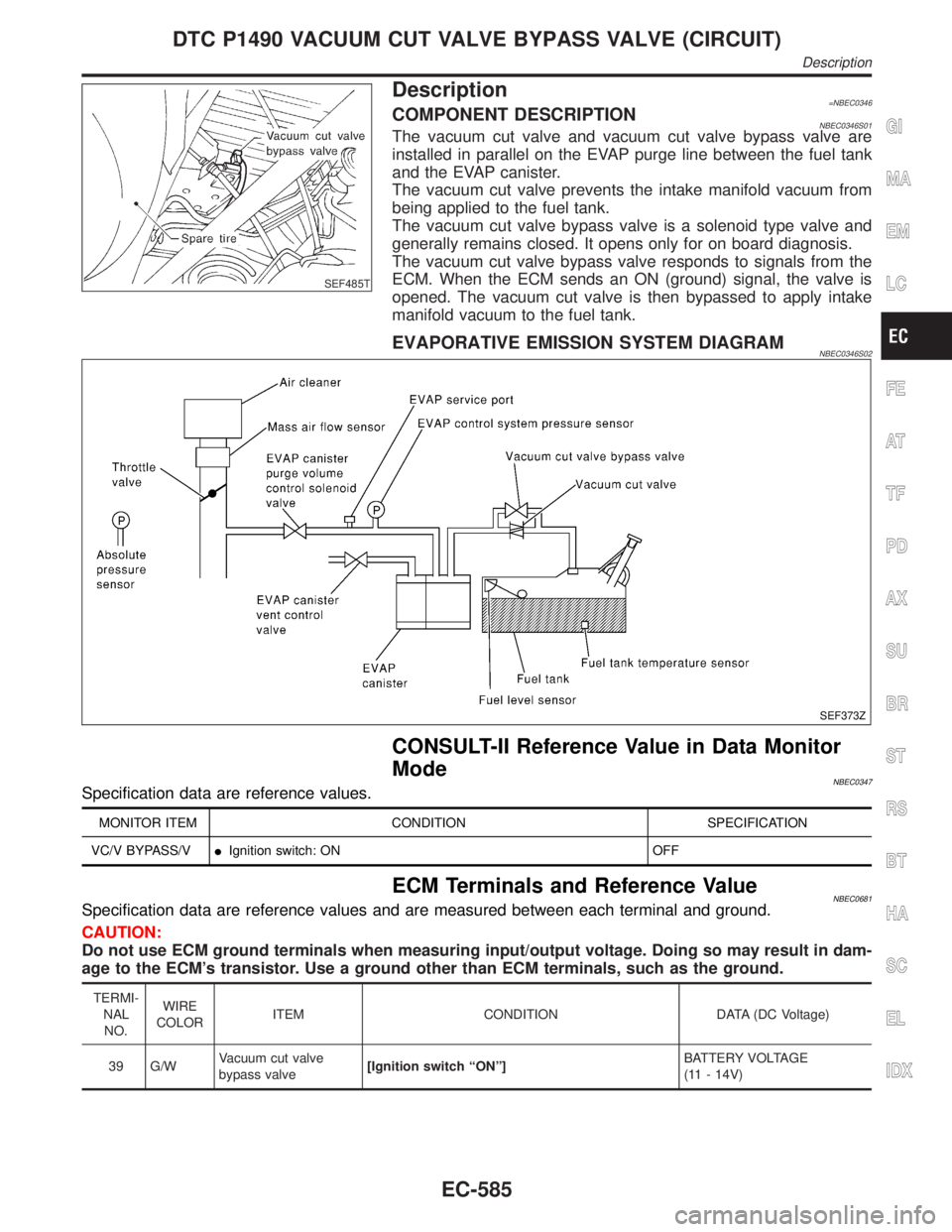
Description=NBEC0346COMPONENT DESCRIPTIONNBEC0346S01The vacuum cut valve and vacuum cut valve bypass valve are
installed in parallel on the EVAP purge line between the fuel tank
and the EVAP canister.
The vacuum cut valve prevents the intake manifold vacuum from
being applied to the fuel tank.
The vacuum cut valve bypass valve is a solenoid type valve and
generally remains closed. It opens only for on board diagnosis.
The vacuum cut valve bypass valve responds to signals from the
ECM. When the ECM sends an ON (ground) signal, the valve is
opened. The vacuum cut valve is then bypassed to apply intake
manifold vacuum to the fuel tank.
EVAPORATIVE EMISSION SYSTEM DIAGRAMNBEC0346S02
SEF373Z
CONSULT-II Reference Value in Data Monitor
Mode
NBEC0347Specification data are reference values.
MONITOR ITEM CONDITION SPECIFICATION
VC/V BYPASS/VIIgnition switch: ON OFF
ECM Terminals and Reference ValueNBEC0681Specification data are reference values and are measured between each terminal and ground.
CAUTION:
Do not use ECM ground terminals when measuring input/output voltage. Doing so may result in dam-
age to the ECM's transistor. Use a ground other than ECM terminals, such as the ground.
TERMI-
NAL
NO.WIRE
COLORITEM CONDITION DATA (DC Voltage)
39 G/WVacuum cut valve
bypass valve[Ignition switch ªONº]BATTERY VOLTAGE
(11 - 14V)
GI
MA
EM
LC
FE
AT
TF
PD
AX
SU
BR
ST
RS
BT
HA
SC
EL
IDX
DTC P1490 VACUUM CUT VALVE BYPASS VALVE (CIRCUIT)
Description
EC-585
Page 1126 of 2395
SEF485T
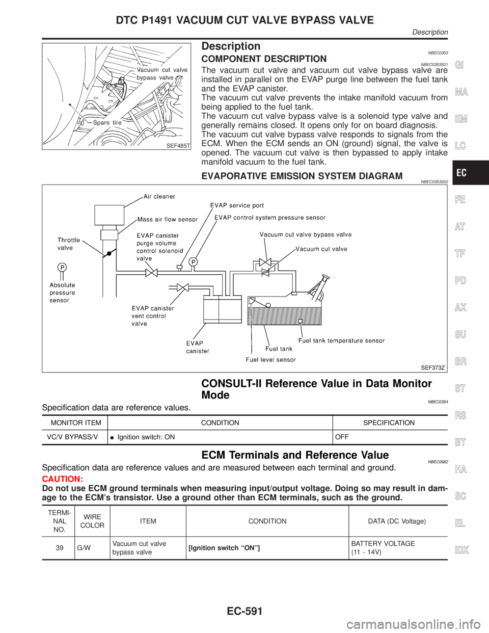
DescriptionNBEC0353COMPONENT DESCRIPTIONNBEC0353S01The vacuum cut valve and vacuum cut valve bypass valve are
installed in parallel on the EVAP purge line between the fuel tank
and the EVAP canister.
The vacuum cut valve prevents the intake manifold vacuum from
being applied to the fuel tank.
The vacuum cut valve bypass valve is a solenoid type valve and
generally remains closed. It opens only for on board diagnosis.
The vacuum cut valve bypass valve responds to signals from the
ECM. When the ECM sends an ON (ground) signal, the valve is
opened. The vacuum cut valve is then bypassed to apply intake
manifold vacuum to the fuel tank.
EVAPORATIVE EMISSION SYSTEM DIAGRAMNBEC0353S02
SEF373Z
CONSULT-II Reference Value in Data Monitor
Mode
NBEC0354Specification data are reference values.
MONITOR ITEM CONDITION SPECIFICATION
VC/V BYPASS/VIIgnition switch: ON OFF
ECM Terminals and Reference ValueNBEC0682Specification data are reference values and are measured between each terminal and ground.
CAUTION:
Do not use ECM ground terminals when measuring input/output voltage. Doing so may result in dam-
age to the ECM's transistor. Use a ground other than ECM terminals, such as the ground.
TERMI-
NAL
NO.WIRE
COLORITEM CONDITION DATA (DC Voltage)
39 G/WVacuum cut valve
bypass valve[Ignition switch ªONº]BATTERY VOLTAGE
(11 - 14V)
GI
MA
EM
LC
FE
AT
TF
PD
AX
SU
BR
ST
RS
BT
HA
SC
EL
IDX
DTC P1491 VACUUM CUT VALVE BYPASS VALVE
Description
EC-591
Page 1128 of 2395
RESULTSº. If ªNGº is displayed, refer to ªDiagnostic
Procedureº, EC-595.
SEF530Q
Overall Function CheckNBEC0358Use this procedure to check the overall function of vacuum cut
valve bypass valve. During this check, the 1st trip DTC might not
be confirmed.
WITH GSTNBEC0358S011) Remove vacuum cut valve and vacuum cut valve bypass valve
as an assembly.
2) Apply vacuum to portAand check that there is no suction from
portB.
3) Apply vacuum to portBand check that there is suction from
portA.
4) Blow air in portBand check that there is a resistance to flow
out of portA.
5) Supply battery voltage to the terminal.
6) Blow air in portAand check that air flows freely out of portB.
7) Blow air in portBand check that air flows freely out of portA.
8) If NG, go to ªDiagnostic Procedureº, EC-595.
GI
MA
EM
LC
FE
AT
TF
PD
AX
SU
BR
ST
RS
BT
HA
SC
EL
IDX
DTC P1491 VACUUM CUT VALVE BYPASS VALVE
DTC Confirmation Procedure (Cont'd)
EC-593
Page 1131 of 2395
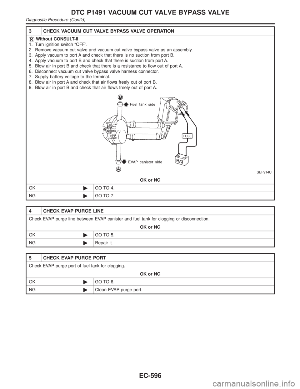
3 CHECK VACUUM CUT VALVE BYPASS VALVE OPERATION
Without CONSULT-II
1. Turn ignition switch ªOFFº.
2. Remove vacuum cut valve and vacuum cut valve bypass valve as an assembly.
3. Apply vacuum to port A and check that there is no suction from port B.
4. Apply vacuum to port B and check that there is suction from port A.
5. Blow air in port B and check that there is a resistance to flow out of port A.
6. Disconnect vacuum cut valve bypass valve harness connector.
7. Supply battery voltage to the terminal.
8. Blow air in port A and check that air flows freely out of port B.
9. Blow air in port B and check that air flows freely out of port A.
SEF914U
OK or NG
OK©GO TO 4.
NG©GO TO 7.
4 CHECK EVAP PURGE LINE
Check EVAP purge line between EVAP canister and fuel tank for clogging or disconnection.
OK or NG
OK©GO TO 5.
NG©Repair it.
5 CHECK EVAP PURGE PORT
Check EVAP purge port of fuel tank for clogging.
OK or NG
OK©GO TO 6.
NG©Clean EVAP purge port.
DTC P1491 VACUUM CUT VALVE BYPASS VALVE
Diagnostic Procedure (Cont'd)
EC-596
Page 1139 of 2395
AEC877A
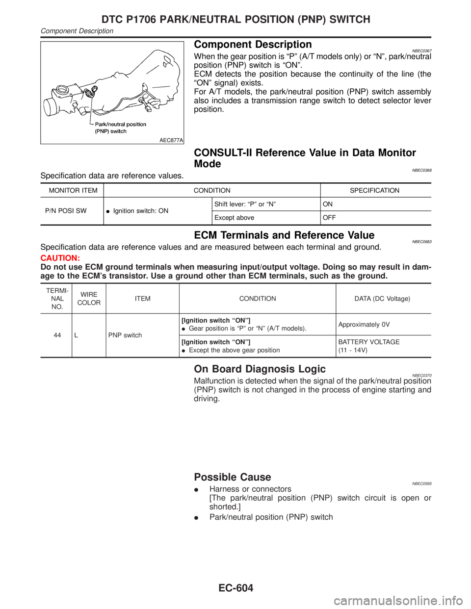
Component DescriptionNBEC0367When the gear position is ªPº (A/T models only) or ªNº, park/neutral
position (PNP) switch is ªONº.
ECM detects the position because the continuity of the line (the
ªONº signal) exists.
For A/T models, the park/neutral position (PNP) switch assembly
also includes a transmission range switch to detect selector lever
position.
CONSULT-II Reference Value in Data Monitor
Mode
NBEC0368Specification data are reference values.
MONITOR ITEM CONDITION SPECIFICATION
P/N POSI SWIIgnition switch: ONShift lever: ªPº or ªNº ON
Except above OFF
ECM Terminals and Reference ValueNBEC0683Specification data are reference values and are measured between each terminal and ground.
CAUTION:
Do not use ECM ground terminals when measuring input/output voltage. Doing so may result in dam-
age to the ECM's transistor. Use a ground other than ECM terminals, such as the ground.
TERMI-
NAL
NO.WIRE
COLORITEM CONDITION DATA (DC Voltage)
44 L PNP switch[Ignition switch ªONº]
IGear position is ªPº or ªNº (A/T models).Approximately 0V
[Ignition switch ªONº]
IExcept the above gear positionBATTERY VOLTAGE
(11 - 14V)
On Board Diagnosis LogicNBEC0370Malfunction is detected when the signal of the park/neutral position
(PNP) switch is not changed in the process of engine starting and
driving.
Possible CauseNBEC0595IHarness or connectors
[The park/neutral position (PNP) switch circuit is open or
shorted.]
IPark/neutral position (PNP) switch
DTC P1706 PARK/NEUTRAL POSITION (PNP) SWITCH
Component Description
EC-604
Page 1141 of 2395
SEF359X
Overall Function Check=NBEC0372Use this procedure to check the overall function of the park/neutral
position (PNP) switch circuit. During this check, a 1st trip DTC
might not be confirmed.
WITH GSTNBEC0372S011) Turn ignition switch ªONº.
2) Check voltage between ECM terminal 44 and body ground
under the following conditions.
Condition (Gear position) Voltage V (Known good data)
ªPº and ªNº position Approx. 0
Except the above position Battery voltage
3) If NG, go to ªDiagnostic Procedureº, EC-608.
DTC P1706 PARK/NEUTRAL POSITION (PNP) SWITCH
Overall Function Check
EC-606
Page 1146 of 2395
SEF018Z
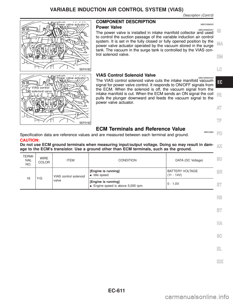
COMPONENT DESCRIPTIONNBEC0596S02Power ValveNBEC0596S0201The power valve is installed in intake manifold collector and used
to control the suction passage of the variable induction air control
system. It is set in the fully closed or fully opened position by the
power valve actuator operated by the vacuum stored in the surge
tank. The vacuum in the surge tank is controlled by the VIAS con-
trol solenoid valve.
SEF019Z
VIAS Control Solenoid ValveNBEC0596S0202The VIAS control solenoid valve cuts the intake manifold vacuum
signal for power valve control. It responds to ON/OFF signals from
the ECM. When the solenoid is off, the vacuum signal from the
intake manifold is cut. When the ECM sends an ON signal the coil
pulls the plunger downward and feeds the vacuum signal to the
power valve actuator.
ECM Terminals and Reference ValueNBEC0684Specification data are reference values and are measured between each terminal and ground.
CAUTION:
Do not use ECM ground terminals when measuring input/output voltage. Doing so may result in dam-
age to the ECM's transistor. Use a ground other than ECM terminals, such as the ground.
TERMI-
NAL
NO.WIRE
COLORITEM CONDITION DATA (DC Voltage)
16 Y/GVIAS control solenoid
valve[Engine is running]
IIdle speedBATTERY VOLTAGE
(11 - 14V)
[Engine is running]
IEngine speed is above 5,000 rpm.0 - 1.0V
GI
MA
EM
LC
FE
AT
TF
PD
AX
SU
BR
ST
RS
BT
HA
SC
EL
IDX
VARIABLE INDUCTION AIR CONTROL SYSTEM (VIAS)
Description (Cont'd)
EC-611