2001 INFINITI QX4 Battery terminal
[x] Cancel search: Battery terminalPage 967 of 2395

SEF197Y
SEF198Y
DTC Confirmation ProcedureNBEC0260CAUTION:
Always drive vehicle at a safe speed.
NOTE:
If ªDTC Confirmation Procedureº has been previously conducted,
always turn ignition switch ªOFFº and wait at least 10 seconds
before conducting the next test.
WITH CONSULT-IINBEC0260S011) Start engine and warm it up to normal operating temperature.
2) Turn ignition switch ªOFFº, wait at least 10 seconds and then
start engine.
3) Select ªCLSD THL/P SWº in ªDATA MONITORº mode.
If ªCLSD THL/P SWº is not available, go to step 5.
4) Check the signal under the following conditions.
Condition Signal indication
Throttle valve: Idle position ON
Throttle valve: Slightly open OFF
If the result is NG, go to ªDiagnostic Procedureº, EC-435.
If OK, go to following step.
5) Select ªDATA MONITORº mode with CONSULT-II.
6) Drive the vehicle for at least 5 consecutive seconds under the
following condition.
THRTL POS SEN More than 2.5V
VHCL SPEED SE More than 5 km/h (3 MPH)
Selector lever Suitable position
Driving locationDriving vehicle uphill (Increased engine load)
will help maintain the driving conditions
required for this test.
7) If 1st trip DTC is detected, go to ªDiagnostic Procedureº,
EC-435.
SEF345X
Overall Function CheckNBEC0261Use this procedure to check the overall function of the closed
throttle position switch circuit. During this check, a 1st trip DTC
might not be confirmed.
WITH GSTNBEC0261S011) Start engine and warm it up to normal operating temperature.
2) Check the voltage between ECM terminal 56 (Closed throttle
position switch signal) and ground under the following condi-
tions.
At idle: Battery voltage
DTC P0510 CLOSED THROTTLE POSITION SWITCH
DTC Confirmation Procedure
EC-432
Page 975 of 2395

System DescriptionNBEC0264This circuit line (LAN) is used to control the smooth shifting up and down of A/T during the hard acceleration/
deceleration.
Pulse signals are exchanged between ECM and TCM (Transmission Control Module).
Be sure to erase the malfunction information such as DTC not only in TCM but also ECM after the A/T
related repair.
ECM Terminals and Reference ValueNBEC0672Specification data are reference values and are measured between each terminal and ground.
CAUTION:
Do not use ECM ground terminals when measuring input/output voltage. Doing so may result in dam-
age to the ECM's transistor. Use a ground other than ECM terminals, such as the ground.
TERMI-
NAL
NO.WIRE
COLORITEM CONDITION DATA (DC Voltage)
114 G/RCommunication line
(LAN)[Engine is running]
IIdle speedApproximately 2V
On Board Diagnosis LogicNBEC0266Malfunction is detected when ECM receives incorrect voltage from
TCM (Transmission Control Module) continuously.
Possible CauseNBEC0517IHarness or connectors
[The communication line circuit between ECM and TCM
(Transmission Control Module) is open or shorted.]
ITCM
IDead (Weak) battery
SEF058Y
DTC Confirmation ProcedureNBEC0267NOTE:
If ªDTC Confirmation Procedureº has been previously conducted,
always turn ignition switch ªOFFº and wait at least 10 seconds
before conducting the next test.
TESTING CONDITION:
Before performing the following procedure, confirm that bat-
tery voltage is more than 10.5V at idle.
WITH CONSULT-IINBEC0267S011) Turn ignition switch ªONº.
DTC P0600 A/T COMMUNICATION LINE
System Description
EC-440
Page 982 of 2395

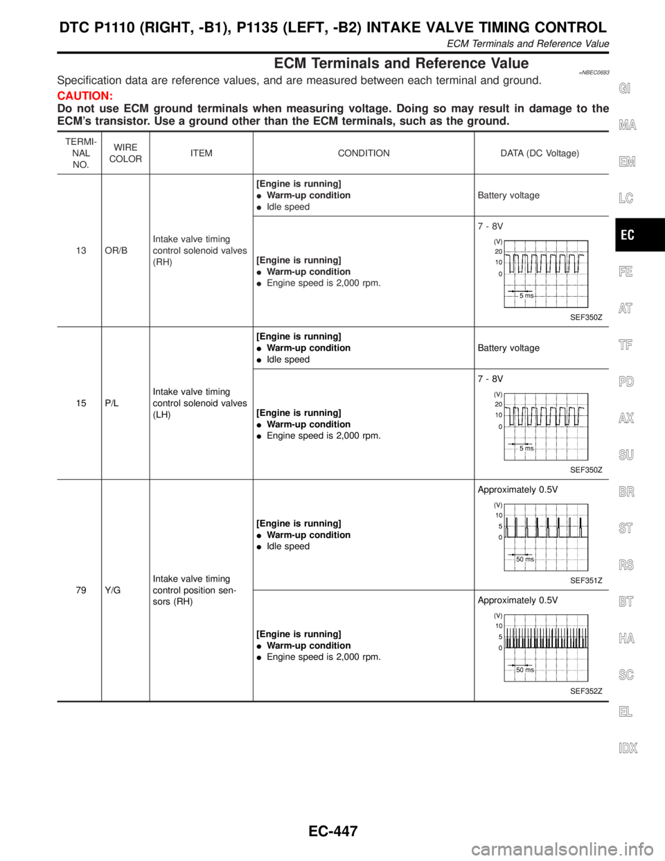
ECM Terminals and Reference Value=NBEC0693Specification data are reference values, and are measured between each terminal and ground.
CAUTION:
Do not use ECM ground terminals when measuring voltage. Doing so may result in damage to the
ECM's transistor. Use a ground other than the ECM terminals, such as the ground.
TERMI-
NAL
NO.WIRE
COLORITEM CONDITION DATA (DC Voltage)
13 OR/BIntake valve timing
control solenoid valves
(RH)[Engine is running]
IWarm-up condition
IIdle speedBattery voltage
[Engine is running]
IWarm-up condition
IEngine speed is 2,000 rpm.7-8V
SEF350Z
15 P/LIntake valve timing
control solenoid valves
(LH)[Engine is running]
IWarm-up condition
IIdle speedBattery voltage
[Engine is running]
IWarm-up condition
IEngine speed is 2,000 rpm.7-8V
SEF350Z
79 Y/GIntake valve timing
control position sen-
sors (RH)[Engine is running]
IWarm-up condition
IIdle speedApproximately 0.5VSEF351Z
[Engine is running]
IWarm-up condition
IEngine speed is 2,000 rpm.Approximately 0.5V
SEF352Z
GI
MA
EM
LC
FE
AT
TF
PD
AX
SU
BR
ST
RS
BT
HA
SC
EL
IDX
DTC P1110 (RIGHT, -B1), P1135 (LEFT, -B2) INTAKE VALVE TIMING CONTROL
ECM Terminals and Reference Value
EC-447
Page 986 of 2395

SEF354Z
Component DescriptionNBEC0697Intake valve timing control solenoid valve is activated by ON/OFF
pulse duty (ratio) signals from the ECM.
The intake valve timing control solenoid valve changes the oil
amount and direction of flow through intake valve timing control unit
or stops oil flow.
The longer pulse width advances valve angle.
The shorter pulse width retards valve angle.
When ON and OFF pulse widths become equal, the solenoid valve
stops oil pressure flow to fix the intake valve angle at the control
position.
CONSULT-II Reference Value in Data Monitor
Mode
NBEC0698Specification data are reference values.
MONITOR ITEM CONDITION SPECIFICATION
INT/V SOL (B1)
INT/V SOL (B2)IEngine: After warming up
IShift lever ªNº
IQuickly depressed accelerator
pedal
INo-loadIdle 0%
2,000 rpm Approximately 40%
ECM Terminals and Reference ValueNBEC0699Specification data are reference values, and are measured between each terminal and ground.
CAUTION:
Do not use ECM ground terminals when measuring input/output voltage. Doing so may result in dam-
age to the ECM's transistor. Use a ground other than the ECM terminals, such as the ground.
TERMI-
NAL
NO.WIRE
COLORITEM CONDITION DATA (DC Voltage)
13 OR/BIntake valve timing
control solenoid valves
(RH)[Engine is running]
IWarm-up condition
IIdle speedBattery voltage
[Engine is running]
IWarm-up condition
IEngine speed is 2,000 rpm.7-8V
SEF350Z
15 P/LIntake valve timing
control solenoid valves
(LH)[Engine is running]
IWarm-up condition
IIdle speedBattery voltage
[Engine is running]
IWarm-up condition
IEngine speed is 2,000 rpm.7-8V
SEF350Z
GI
MA
EM
LC
FE
AT
TF
PD
AX
SU
BR
ST
RS
BT
HA
SC
EL
IDX
D T C P 1111(RIGHT, -B1), P1136 (LEFT, -B2) INTAKE VALVE TIMING CONTROL
SOLENOID VALVE (CIRCUIT)
Component Description
EC-451
Page 990 of 2395

Diagnostic ProcedureNBEC0704
1 CHECK OVERALL FUNCTION
With CONSULT-II
1. Start engine and warm it up to normal operating temperature.
2. Perform ªTARGET INT/V TIMº in ªACTIVE TESTº mode with CONSULT-II.
3. Hold engine speed at 1,500 to 2,500 rpm under the following step.
4. Touch ªUPº or ªDOWNº on CONSULT-II screen.
SEF355Z
5. Check the following.
IThe angle of a corresponding INT/V TIM (B1)/(B2) to setting TARGET INT/V TIM confirms the variation.
Without CONSULT-II
1. Remove intake valve timing control solenoid valve.
2. Reconnect intake valve timing control solenoid valve harness connector.
3. Supply intake valve timing control solenoid valve terminals with battery voltage as shown below.
SEF356Z
Clicking noise should be heard.
OK or NG
OK©INSPECTION END
NG©GO TO 2.
GI
MA
EM
LC
FE
AT
TF
PD
AX
SU
BR
ST
RS
BT
HA
SC
EL
IDX
D T C P 1111(RIGHT, -B1), P1136 (LEFT, -B2) INTAKE VALVE TIMING CONTROL
SOLENOID VALVE (CIRCUIT)
Diagnostic Procedure
EC-455
Page 994 of 2395

SEF002Z
COMPONENT DESCRIPTIONNBEC0523S02Swirl Control Valve Control Solenoid ValveNBEC0523S0201The swirl control valve control solenoid valve responds to signals
from the ECM. When the ECM sends an ON (ground) signal, the
solenoid valve is bypassed to apply intake manifold vacuum to the
swirl control valve actuator. This operation closes the swirl control
valve. When the ECM sends an OFF signal, the vacuum signal is
cut and the swirl control valve opens.
CONSULT-II Reference Value in Data Monitor
Mode
NBEC0524Specification data are reference values.
MONITOR ITEM CONDITION SPECIFICATION
SWRL CONT S/VIEngine speed: IdleEngine coolant temperature is
between 15ÉC (59ÉF) to 50ÉC
(122ÉF).ON
Engine coolant temperature is
above 55ÉC (131ÉF).OFF
ECM Terminals and Reference ValueNBEC0673Specification data are reference values and are measured between each terminal and ground.
CAUTION:
Do not use ECM ground terminals when measuring input/output voltage. Doing so may result in dam-
age to the ECM's transistor. Use a ground other than ECM terminals, such as the ground.
TERMI-
NAL
NO.WIRE
COLORITEM CONDITION DATA (DC Voltage)
29 GSwirl control valve con-
trol solenoid valve[Engine is running]
IIdle speed
IEngine coolant temperature is between 15 to
50ÉC (59 to 122ÉF).0 - 1.0V
[Engine is running]
IIdle speed
IEngine coolant temperature is above 55ÉC
(131ÉF).BATTERY VOLTAGE
(11 - 14V)
On Board Diagnosis LogicNBEC0526Malfunction is detected when
(Malfunction A)An improper voltage signal is sent to ECM through
swirl control valve control solenoid valve,
(Malfunction B)The vacuum signal is not sent to swirl control
valve under specified driving conditions, even though swirl control
valve control solenoid valve is ON,
(Malfunction C)The vacuum signal is sent to swirl control valve
even though swirl control valve control solenoid valve is OFF.
GI
MA
EM
LC
FE
AT
TF
PD
AX
SU
BR
ST
RS
BT
HA
SC
EL
IDX
DTC P1130 SWIRL CONTROL VALVE CONTROL SOLENOID VALVE
Description (Cont'd)
EC-459
Page 1077 of 2395

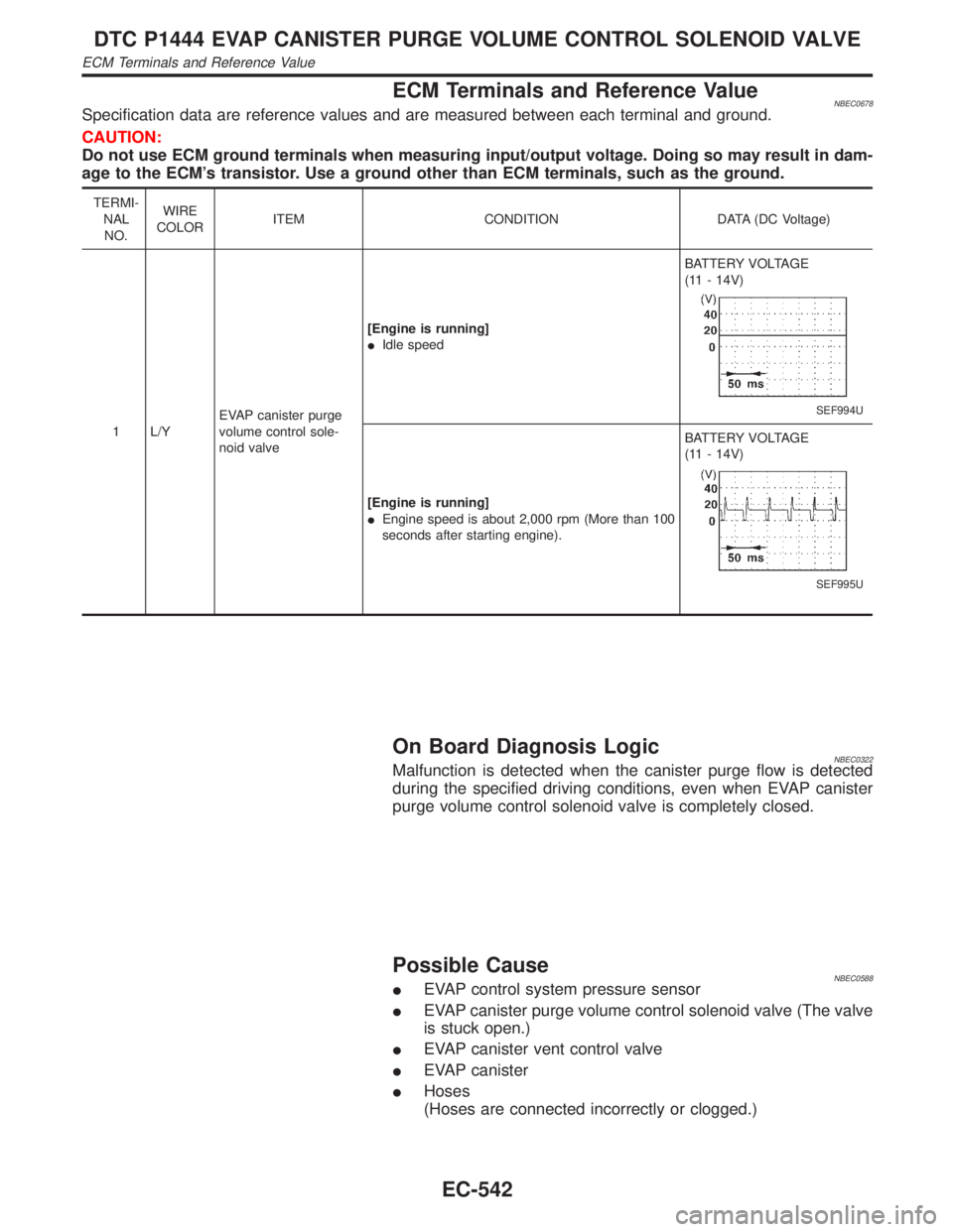
ECM Terminals and Reference ValueNBEC0678Specification data are reference values and are measured between each terminal and ground.
CAUTION:
Do not use ECM ground terminals when measuring input/output voltage. Doing so may result in dam-
age to the ECM's transistor. Use a ground other than ECM terminals, such as the ground.
TERMI-
NAL
NO.WIRE
COLORITEM CONDITION DATA (DC Voltage)
1 L/YEVAP canister purge
volume control sole-
noid valve[Engine is running]
IIdle speedBATTERY VOLTAGE
(11 - 14V)
SEF994U
[Engine is running]
IEngine speed is about 2,000 rpm (More than 100
seconds after starting engine).BATTERY VOLTAGE
(11 - 14V)
SEF995U
On Board Diagnosis LogicNBEC0322Malfunction is detected when the canister purge flow is detected
during the specified driving conditions, even when EVAP canister
purge volume control solenoid valve is completely closed.
Possible CauseNBEC0588IEVAP control system pressure sensor
IEVAP canister purge volume control solenoid valve (The valve
is stuck open.)
IEVAP canister vent control valve
IEVAP canister
IHoses
(Hoses are connected incorrectly or clogged.)
DTC P1444 EVAP CANISTER PURGE VOLUME CONTROL SOLENOID VALVE
ECM Terminals and Reference Value
EC-542
Page 1088 of 2395

SEF032W
SEF143S
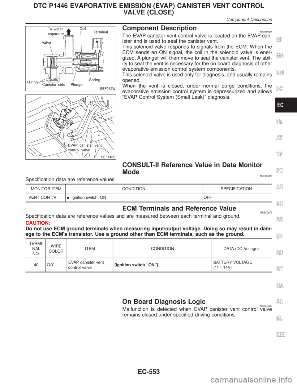
Component DescriptionNBEC0326The EVAP canister vent control valve is located on the EVAP can-
ister and is used to seal the canister vent.
This solenoid valve responds to signals from the ECM. When the
ECM sends an ON signal, the coil in the solenoid valve is ener-
gized. A plunger will then move to seal the canister vent. The abil-
ity to seal the vent is necessary for the on board diagnosis of other
evaporative emission control system components.
This solenoid valve is used only for diagnosis, and usually remains
opened.
When the vent is closed, under normal purge conditions, the
evaporative emission control system is depressurized and allows
ªEVAP Control System (Small Leak)º diagnosis.
CONSULT-II Reference Value in Data Monitor
Mode
NBEC0327Specification data are reference values.
MONITOR ITEM CONDITION SPECIFICATION
VENT CONT/VIIgnition switch: ON OFF
ECM Terminals and Reference ValueNBEC0679Specification data are reference values and are measured between each terminal and ground.
CAUTION:
Do not use ECM ground terminals when measuring input/output voltage. Doing so may result in dam-
age to the ECM's transistor. Use a ground other than ECM terminals, such as the ground.
TERMI-
NAL
NO.WIRE
COLORITEM CONDITION DATA (DC Voltage)
40 G/YEVAP canister vent
control valve[Ignition switch ªONº]BATTERY VOLTAGE
(11 - 14V)
On Board Diagnosis LogicNBEC0329Malfunction is detected when EVAP canister vent control valve
remains closed under specified driving conditions.
GI
MA
EM
LC
FE
AT
TF
PD
AX
SU
BR
ST
RS
BT
HA
SC
EL
IDX
DTC P1446 EVAPORATIVE EMISSION (EVAP) CANISTER VENT CONTROL
VALVE (CLOSE)
Component Description
EC-553