2001 INFINITI QX4 turn signal
[x] Cancel search: turn signalPage 1177 of 2395
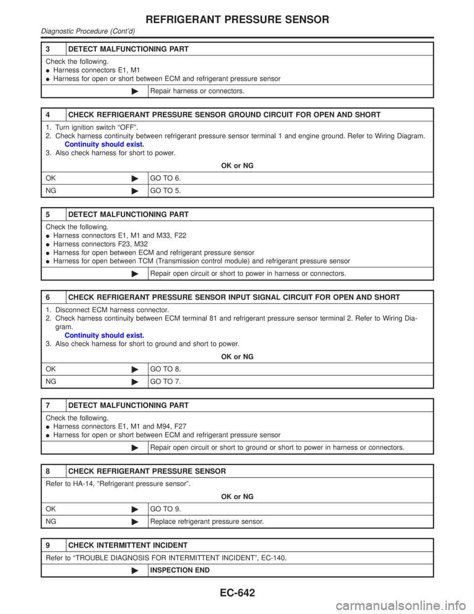
3 DETECT MALFUNCTIONING PART
Check the following.
IHarness connectors E1, M1
IHarness for open or short between ECM and refrigerant pressure sensor
©Repair harness or connectors.
4 CHECK REFRIGERANT PRESSURE SENSOR GROUND CIRCUIT FOR OPEN AND SHORT
1. Turn ignition switch ªOFFº.
2. Check harness continuity between refrigerant pressure sensor terminal 1 and engine ground. Refer to Wiring Diagram.
Continuity should exist.
3. Also check harness for short to power.
OK or NG
OK©GO TO 6.
NG©GO TO 5.
5 DETECT MALFUNCTIONING PART
Check the following.
IHarness connectors E1, M1 and M33, F22
IHarness connectors F23, M32
IHarness for open between ECM and refrigerant pressure sensor
IHarness for open between TCM (Transmission control module) and refrigerant pressure sensor
©Repair open circuit or short to power in harness or connectors.
6 CHECK REFRIGERANT PRESSURE SENSOR INPUT SIGNAL CIRCUIT FOR OPEN AND SHORT
1. Disconnect ECM harness connector.
2. Check harness continuity between ECM terminal 81 and refrigerant pressure sensor terminal 2. Refer to Wiring Dia-
gram.
Continuity should exist.
3. Also check harness for short to ground and short to power.
OK or NG
OK©GO TO 8.
NG©GO TO 7.
7 DETECT MALFUNCTIONING PART
Check the following.
IHarness connectors E1, M1 and M94, F27
IHarness for open or short between ECM and refrigerant pressure sensor
©Repair open circuit or short to ground or short to power in harness or connectors.
8 CHECK REFRIGERANT PRESSURE SENSOR
Refer to HA-14, ªRefrigerant pressure sensorº.
OK or NG
OK©GO TO 9.
NG©Replace refrigerant pressure sensor.
9 CHECK INTERMITTENT INCIDENT
Refer to ªTROUBLE DIAGNOSIS FOR INTERMITTENT INCIDENTº, EC-140.
©INSPECTION END
REFRIGERANT PRESSURE SENSOR
Diagnostic Procedure (Cont'd)
EC-642
Page 1180 of 2395
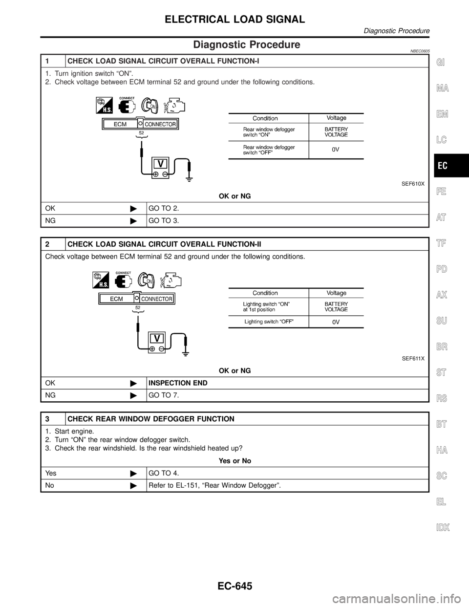
Diagnostic ProcedureNBEC0605
1 CHECK LOAD SIGNAL CIRCUIT OVERALL FUNCTION-I
1. Turn ignition switch ªONº.
2. Check voltage between ECM terminal 52 and ground under the following conditions.
SEF610X
OK or NG
OK©GO TO 2.
NG©GO TO 3.
2 CHECK LOAD SIGNAL CIRCUIT OVERALL FUNCTION-II
Check voltage between ECM terminal 52 and ground under the following conditions.
SEF611X
OK or NG
OK©INSPECTION END
NG©GO TO 7.
3 CHECK REAR WINDOW DEFOGGER FUNCTION
1. Start engine.
2. Turn ªONº the rear window defogger switch.
3. Check the rear windshield. Is the rear windshield heated up?
YesorNo
Ye s©GO TO 4.
No©Refer to EL-151, ªRear Window Defoggerº.
GI
MA
EM
LC
FE
AT
TF
PD
AX
SU
BR
ST
RS
BT
HA
SC
EL
IDX
ELECTRICAL LOAD SIGNAL
Diagnostic Procedure
EC-645
Page 1181 of 2395
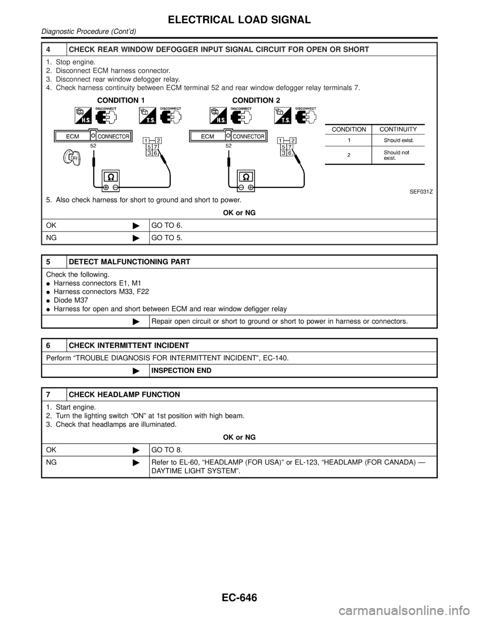
4 CHECK REAR WINDOW DEFOGGER INPUT SIGNAL CIRCUIT FOR OPEN OR SHORT
1. Stop engine.
2. Disconnect ECM harness connector.
3. Disconnect rear window defogger relay.
4. Check harness continuity between ECM terminal 52 and rear window defogger relay terminals 7.
SEF031Z
5. Also check harness for short to ground and short to power.
OK or NG
OK©GO TO 6.
NG©GO TO 5.
5 DETECT MALFUNCTIONING PART
Check the following.
IHarness connectors E1, M1
IHarness connectors M33, F22
IDiode M37
IHarness for open and short between ECM and rear window defigger relay
©Repair open circuit or short to ground or short to power in harness or connectors.
6 CHECK INTERMITTENT INCIDENT
Perform ªTROUBLE DIAGNOSIS FOR INTERMITTENT INCIDENTº, EC-140.
©INSPECTION END
7 CHECK HEADLAMP FUNCTION
1. Start engine.
2. Turn the lighting switch ªONº at 1st position with high beam.
3. Check that headlamps are illuminated.
OK or NG
OK©GO TO 8.
NG©Refer to EL-60, ªHEADLAMP (FOR USA)º or EL-123, ªHEADLAMP (FOR CANADA) Ð
DAYTIME LIGHT SYSTEMº.
ELECTRICAL LOAD SIGNAL
Diagnostic Procedure (Cont'd)
EC-646
Page 1186 of 2395
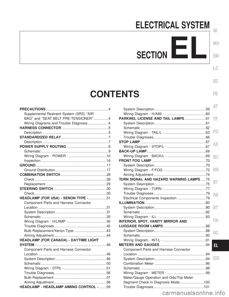
ELECTRICAL SYSTEM
SECTION
EL
CONTENTS
PRECAUTIONS...............................................................4
Supplemental Restraint System (SRS)²AIR
BAG²and²SEAT BELT PRE-TENSIONER²...............4
Wiring Diagrams and Trouble Diagnosis .....................4
HARNESS CONNECTOR................................................5
Description ...................................................................5
STANDARDIZED RELAY................................................7
Description ...................................................................7
POWER SUPPLY ROUTING...........................................9
Schematic ....................................................................9
Wiring Diagram - POWER - ......................................10
Inspection...................................................................16
GROUND........................................................................17
Ground Distribution ....................................................17
COMBINATION SWITCH..............................................28
Check .........................................................................28
Replacement ..............................................................29
STEERING SWITCH......................................................30
Check .........................................................................30
HEADLAMP (FOR USA) - XENON TYPE -..................31
Component Parts and Harness Connector
Location .....................................................................31
System Description ....................................................31
Schematic ..................................................................35
Wiring Diagram - H/LAMP -.......................................36
Trouble Diagnoses.....................................................40
Bulb Replacement/Xenon Type .................................43
Aiming Adjustment .....................................................44
HEADLAMP (FOR CANADA) - DAYTIME LIGHT
SYSTEM -......................................................................46
Component Parts and Harness Connector
Location .....................................................................46
System Description ....................................................46
Schematic ..................................................................50
Wiring Diagram - DTRL - ...........................................51
Trouble Diagnoses.....................................................56
Bulb Replacement .....................................................57
Aiming Adjustment .....................................................58
HEADLAMP - HEADLAMP AIMING CONTROL -........59System Description ....................................................59
Wiring Diagram - H/AIM - ..........................................60
PARKING, LICENSE AND TAIL LAMPS.....................61
System Description ....................................................61
Schematic ..................................................................62
Wiring Diagram - TAIL/L - ..........................................63
Trouble Diagnoses.....................................................66
STOP LAMP..................................................................67
Wiring Diagram - STOP/L - .......................................67
BACK-UP LAMP............................................................69
Wiring Diagram - BACK/L - .......................................69
FRONT FOG LAMP.......................................................70
System Description ....................................................70
Wiring Diagram - F/FOG - .........................................72
Aiming Adjustment .....................................................74
TURN SIGNAL AND HAZARD WARNING LAMPS.....75
System Description ....................................................75
Wiring Diagram - TURN - ..........................................77
Trouble Diagnoses.....................................................79
Electrical Components Inspection .............................79
ILLUMINATION..............................................................80
System Description ....................................................80
Schematic ..................................................................82
Wiring Diagram - ILL - ...............................................83
INTERIOR, SPOT, VANITY MIRROR AND
LUGGAGE ROOM LAMPS...........................................88
System Description ....................................................88
Schematic ..................................................................90
Wiring Diagram - INT/L - ...........................................91
METERS AND GAUGES...............................................94
Component Parts and Harness Connector
Location .....................................................................94
System Description ....................................................94
Combination Meter ....................................................96
Schematic ..................................................................98
Wiring Diagram - METER - .......................................99
Meter/Gauge Operation and Odo/Trip Meter
Segment Check in Diagnosis Mode ........................100
Trouble Diagnoses...................................................101
GI
MA
EM
LC
EC
FE
AT
TF
PD
AX
SU
BR
ST
RS
BT
HA
SC
IDX
Page 1217 of 2395
![INFINITI QX4 2001 Factory Service Manual When the ignition switch is in the ACC or ON position, power is supplied
Ito auto light control unit terminal 2
Ithrough 10A fuse [No. 9, located in the fuse block (J/B)]
Ground is supplied
Ito headla INFINITI QX4 2001 Factory Service Manual When the ignition switch is in the ACC or ON position, power is supplied
Ito auto light control unit terminal 2
Ithrough 10A fuse [No. 9, located in the fuse block (J/B)]
Ground is supplied
Ito headla](/manual-img/42/57027/w960_57027-1216.png)
When the ignition switch is in the ACC or ON position, power is supplied
Ito auto light control unit terminal 2
Ithrough 10A fuse [No. 9, located in the fuse block (J/B)]
Ground is supplied
Ito headlamp battery saver control unit terminals 4 and 11
Ithrough body grounds M77 and M111, and M4,M66 and M147
Ito auto light control unit terminal 5
Ithrough body grounds M4, M66 and M147.
Power Supply to Low Beam and High BeamNBEL0188S0101When lighting switch is in 2ND or PASS position, ground is supplied
Ito headlamp relay (LH and RH) terminal 2 from headlamp battery saver control unit terminals 2 and 8
Ithrough headlamp battery saver control unit terminals 3 and 9,
Ifrom lighting switch terminal 12.
Headlamp relays (LH and RH) are energized and then power is supplied to headlamps (LH and RH).
LOW BEAM OPERATIONNBEL0188S02When the lighting switch is turned to the 2ND position and placed in LOW (ªBº) position, power is supplied
Ifrom terminal 7 of each headlamp relay
Ito terminal 3 of each headlamp
Ground is supplied
Ito terminal 4 of each headlamp
Ithrough body grounds E13 and E41.
With power and ground supplied, the headlamp(s) will illuminate.
HIGH BEAM OPERATION/FLASH-TO-PASS OPERATIONNBEL0188S03When the lighting switch is turned to the 2ND position and placed in HIGH (ªAº) position or PASS (ªCº) position,
power is supplied
Ifrom terminal 5 of headlamp LH relay
Ito terminal 1 of headlamp LH, and
Ito combination meter terminal 26 for the HIGH BEAM indicator
Ifrom terminal 5 of headlamp RH relay
Ito terminal 1 of headlamp RH.
Ground is supplied
Ito headlamp LH terminal 2
Ito combination meter terminal 27 for the HIGH BEAM indicator
Ithrough lighting switch terminals 6 and 5
Ithrough body grounds E13 and E41, and
Ito headlamp RH terminal 2
Ithrough lighting switch terminals 9 and 8
Ithrough body grounds E13 and E41.
With power and ground supplied, the high beams and the high beam indicator illuminate.
BATTERY SAVER CONTROLNBEL0188S04When the ignition switch is turned from ON (or START) to OFF (or ACC) positions while headlamps illuminate,
the RAP signal is supplied to terminal 10 of the headlamp battery saver control unit from smart entrance con-
trol unit terminal 5.
After counting 45 seconds by the RAP signal from the smart entrance control unit to headlamp battery saver
control unit, the ground supply to terminal 2 of the headlamp LH and RH relay from headlamp battery saver
control unit terminals 2 and 8 is terminated.
Then the headlamps are turned off.
The headlamps are turned off when driver or passenger side door is opened even if 45 seconds have not
passed after ignition switch is turned from ON (or START) to OFF (or ACC) positions while headlamps are
illuminated.
When the lighting switch is turned from OFF to 2ND after headlamps are turned to off by the battery saver
control, ground is supplied
HEADLAMP (FOR USA) Ð XENON TYPE Ð
System Description (Cont'd)
EL-32
Page 1228 of 2395
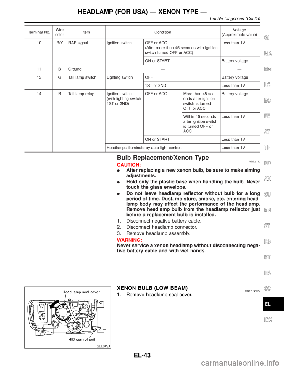
Terminal No.Wire
colorItem ConditionVoltage
(Approximate value)
10 R/Y RAP signal Ignition switch OFF or ACC
(After more than 45 seconds with ignition
switch turned OFF or ACC)Less than 1V
ON or START Battery voltage
11 B Ground Ð Ð
13 G Tail lamp switch Lighting switch OFF Battery voltage
1ST or 2ND Less than 1V
14 R Tail lamp relay Ignition switch
(with lighting switch
1ST or 2ND)OFF or ACC More than 45 sec-
onds after ignition
switch is turned
OFF or ACCBattery voltage
Within 45 seconds
after ignition switch
is turned OFF or
ACCLess than 1V
ON or START Less than 1V
Headlamps illuminate by auto light control. Less than 1V
Bulb Replacement/Xenon TypeNBEL0190CAUTION:
IAfter replacing a new xenon bulb, be sure to make aiming
adjustments.
IHold only the plastic base when handling the bulb. Never
touch the glass envelope.
IDo not leave headlamp reflector without bulb for a long
period of time. Dust, moisture, smoke, etc. entering head-
lamp body may affect the performance of the headlamp.
Remove headlamp bulb from the headlamp reflector just
before a replacement bulb is installed.
1. Disconnect negative battery cable.
2. Disconnect headlamp connector.
3. Remove headlamp assembly.
WARNING:
Never service a xenon headlamp without disconnecting nega-
tive battery cable and with wet hands.
SEL349X
XENON BULB (LOW BEAM)NBEL0190S011. Remove headlamp seal cover.
GI
MA
EM
LC
EC
FE
AT
TF
PD
AX
SU
BR
ST
RS
BT
HA
SC
IDX
HEADLAMP (FOR USA) Ð XENON TYPE Ð
Trouble Diagnoses (Cont'd)
EL-43
Page 1233 of 2395
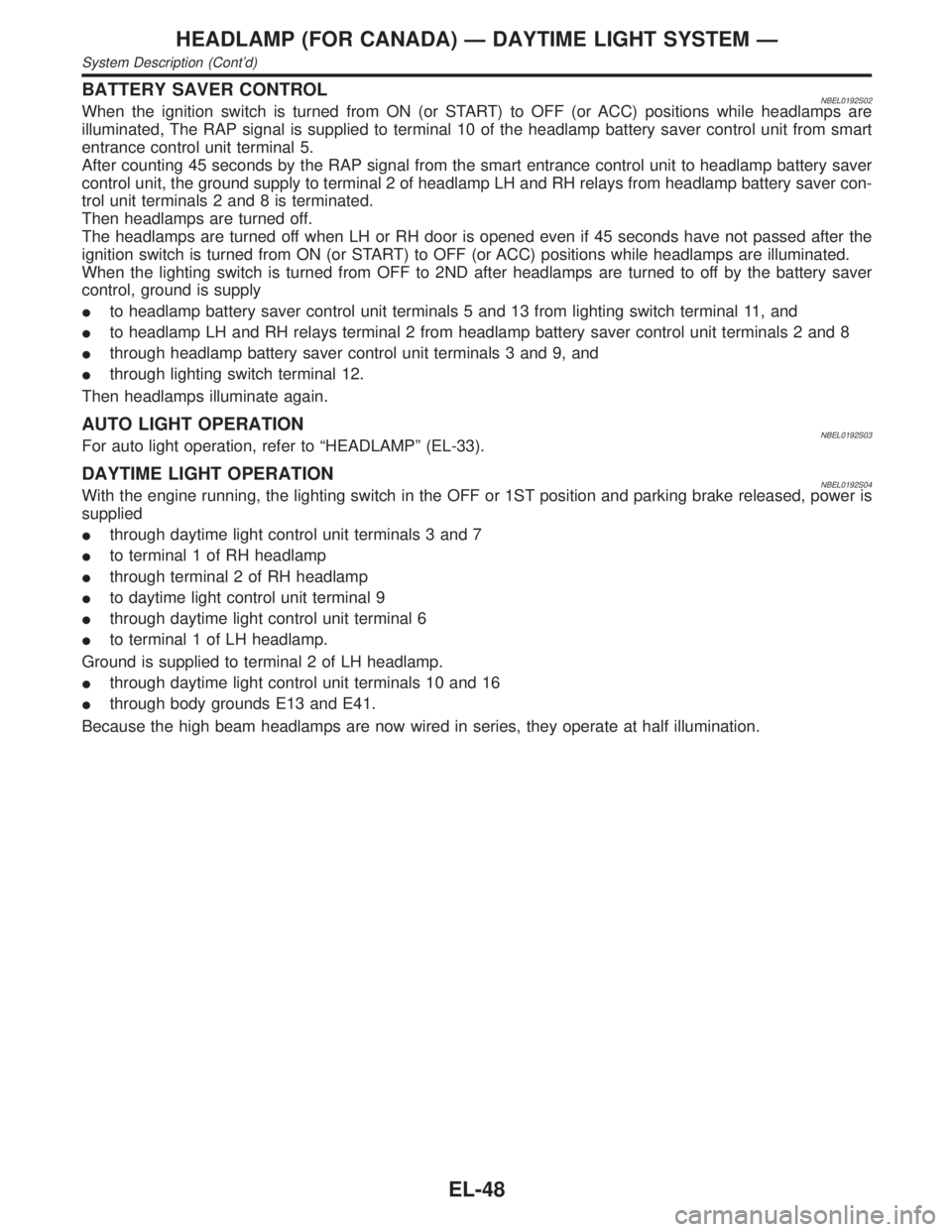
BATTERY SAVER CONTROLNBEL0192S02When the ignition switch is turned from ON (or START) to OFF (or ACC) positions while headlamps are
illuminated, The RAP signal is supplied to terminal 10 of the headlamp battery saver control unit from smart
entrance control unit terminal 5.
After counting 45 seconds by the RAP signal from the smart entrance control unit to headlamp battery saver
control unit, the ground supply to terminal 2 of headlamp LH and RH relays from headlamp battery saver con-
trol unit terminals 2 and 8 is terminated.
Then headlamps are turned off.
The headlamps are turned off when LH or RH door is opened even if 45 seconds have not passed after the
ignition switch is turned from ON (or START) to OFF (or ACC) positions while headlamps are illuminated.
When the lighting switch is turned from OFF to 2ND after headlamps are turned to off by the battery saver
control, ground is supply
Ito headlamp battery saver control unit terminals 5 and 13 from lighting switch terminal 11, and
Ito headlamp LH and RH relays terminal 2 from headlamp battery saver control unit terminals 2 and 8
Ithrough headlamp battery saver control unit terminals 3 and 9, and
Ithrough lighting switch terminal 12.
Then headlamps illuminate again.
AUTO LIGHT OPERATIONNBEL0192S03For auto light operation, refer to ªHEADLAMPº (EL-33).
DAYTIME LIGHT OPERATIONNBEL0192S04With the engine running, the lighting switch in the OFF or 1ST position and parking brake released, power is
supplied
Ithrough daytime light control unit terminals 3 and 7
Ito terminal 1 of RH headlamp
Ithrough terminal 2 of RH headlamp
Ito daytime light control unit terminal 9
Ithrough daytime light control unit terminal 6
Ito terminal 1 of LH headlamp.
Ground is supplied to terminal 2 of LH headlamp.
Ithrough daytime light control unit terminals 10 and 16
Ithrough body grounds E13 and E41.
Because the high beam headlamps are now wired in series, they operate at half illumination.
HEADLAMP (FOR CANADA) Ð DAYTIME LIGHT SYSTEM Ð
System Description (Cont'd)
EL-48
Page 1241 of 2395
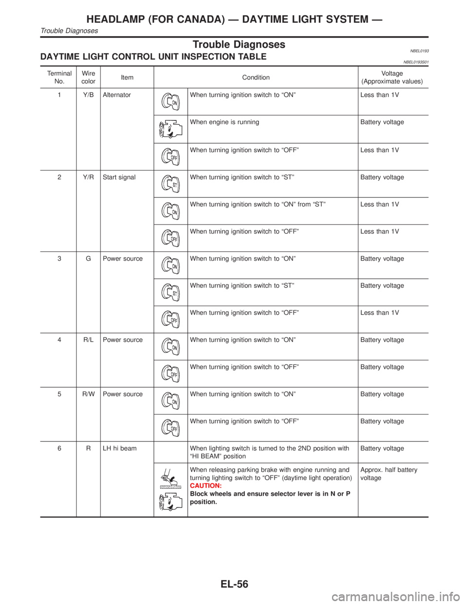
Trouble DiagnosesNBEL0193DAYTIME LIGHT CONTROL UNIT INSPECTION TABLENBEL0193S01
Terminal
No.Wire
colorItem ConditionVoltage
(Approximate values)
1 Y/B Alternator
When turning ignition switch to ªONº Less than 1V
When engine is running Battery voltage
When turning ignition switch to ªOFFº Less than 1V
2 Y/R Start signal
When turning ignition switch to ªSTº Battery voltage
When turning ignition switch to ªONº from ªSTº Less than 1V
When turning ignition switch to ªOFFº Less than 1V
3 G Power source
When turning ignition switch to ªONº Battery voltage
When turning ignition switch to ªSTº Battery voltage
When turning ignition switch to ªOFFº Less than 1V
4 R/L Power source
When turning ignition switch to ªONº Battery voltage
When turning ignition switch to ªOFFº Battery voltage
5 R/W Power source
When turning ignition switch to ªONº Battery voltage
When turning ignition switch to ªOFFº Battery voltage
6 R LH hi beam When lighting switch is turned to the 2ND position with
ªHI BEAMº positionBattery voltage
When releasing parking brake with engine running and
turning lighting switch to ªOFFº (daytime light operation)
CAUTION:
Block wheels and ensure selector lever is in N or P
position.Approx. half battery
voltage
HEADLAMP (FOR CANADA) Ð DAYTIME LIGHT SYSTEM Ð
Trouble Diagnoses
EL-56