Page 1002 of 2395

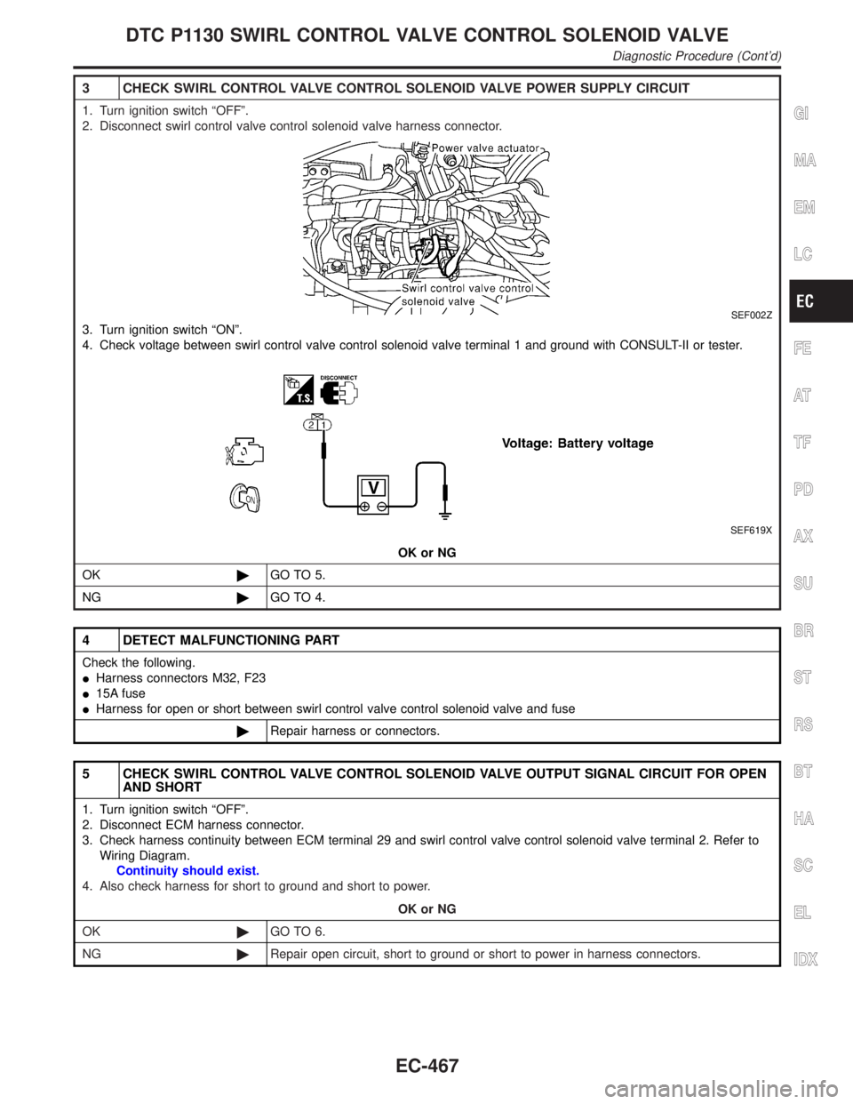
3 CHECK SWIRL CONTROL VALVE CONTROL SOLENOID VALVE POWER SUPPLY CIRCUIT
1. Turn ignition switch ªOFFº.
2. Disconnect swirl control valve control solenoid valve harness connector.
SEF002Z
3. Turn ignition switch ªONº.
4. Check voltage between swirl control valve control solenoid valve terminal 1 and ground with CONSULT-II or tester.
SEF619X
OK or NG
OK©GO TO 5.
NG©GO TO 4.
4 DETECT MALFUNCTIONING PART
Check the following.
IHarness connectors M32, F23
I15A fuse
IHarness for open or short between swirl control valve control solenoid valve and fuse
©Repair harness or connectors.
5 CHECK SWIRL CONTROL VALVE CONTROL SOLENOID VALVE OUTPUT SIGNAL CIRCUIT FOR OPEN
AND SHORT
1. Turn ignition switch ªOFFº.
2. Disconnect ECM harness connector.
3. Check harness continuity between ECM terminal 29 and swirl control valve control solenoid valve terminal 2. Refer to
Wiring Diagram.
Continuity should exist.
4. Also check harness for short to ground and short to power.
OK or NG
OK©GO TO 6.
NG©Repair open circuit, short to ground or short to power in harness connectors.
GI
MA
EM
LC
FE
AT
TF
PD
AX
SU
BR
ST
RS
BT
HA
SC
EL
IDX
DTC P1130 SWIRL CONTROL VALVE CONTROL SOLENOID VALVE
Diagnostic Procedure (Cont'd)
EC-467
Page 1006 of 2395

9 CHECK SWIRL CONTROL VALVE CONTROL VACUUM CHECK SWITCH
1. Turn ignition switch ªOFFº.
2. Disconnect vacuum hose connected to swirl control valve control vacuum check switch.
3. Attach vacuum pump to swirl control valve control vacuum check switch.
4. Turn ignition switch ªONº.
5. Check voltage between ECM terminal 55 and ground under the following conditions.
SEF709X
OK or NG
OK©GO TO 10.
NG©Replace swirl control valve control vacuum check switch.
10 CHECK MASS AIR FLOW SENSOR
1. Reconnect harness connectors disconnected.
2. Start engine and warm it up to normal operating temperature.
3. Check voltage between ECM terminal 61 (Mass air flow sensor signal) and ground.
SEF298X
4. If the voltage is out of specification, disconnect MAFS harness connector and connect it again.
Then repeat above check.
OK or NG
OK (With CONSULT-II)©GO TO 11.
OK (Without CONSULT-
II)©GO TO 12.
NG©Replace mass air flow sensor.
GI
MA
EM
LC
FE
AT
TF
PD
AX
SU
BR
ST
RS
BT
HA
SC
EL
IDX
DTC P1130 SWIRL CONTROL VALVE CONTROL SOLENOID VALVE
Diagnostic Procedure (Cont'd)
EC-471
Page 1008 of 2395

12 CHECK THROTTLE POSITION SENSOR
Without CONSULT-II
1. Start engine and warm it up to normal operating temperature.
2. Stop engine (ignition switch OFF).
3. Remove the vacuum hose connected to the throttle opener.
4. Connect suitable vacuum hose to the vacuum pump and the opener.
5. Apply vacuum [more than þ40.0 kPa (þ300 mmHg, þ11.81 inHg)] until the throttle drum becomes free from the rod of
the throttle opener.
SEF793W
6. Turn ignition switch ON.
7. Check voltage between ECM terminal 91 (Throttle position sensor signal) and ground.
Voltage measurement must be made with throttle position sensor installed in vehicle.
MTBL0231
OK or NG
OK©GO TO 14.
NG©GO TO 13.
13 ADJUST CLOSED THROTTLE POSITION SWITCH
Adjust closed throttle position switch. Refer to ªBasic Inspectionº, EC-101.
MTBL0655
OK or NG
OK©GO TO 14.
NG©Replace throttle position sensor. To adjust it, perform ªBasic Inspectionº, EC-101.
GI
MA
EM
LC
FE
AT
TF
PD
AX
SU
BR
ST
RS
BT
HA
SC
EL
IDX
DTC P1130 SWIRL CONTROL VALVE CONTROL SOLENOID VALVE
Diagnostic Procedure (Cont'd)
EC-473
Page 1011 of 2395
4 DETECT MALFUNCTIONING PART
Check the following.
IHarness connectors M32, F23
I15A fuse
IHarness for open or short between swirl control valve control solenoid valve and fuse
©Repair harness or connectors.
5 CHECK SWIRL CONTROL VALVE CONTROL SOLENOID VALVE OUTPUT SIGNAL CIRCUIT FOR OPEN
AND SHORT
1. Turn ignition switch ªOFFº.
2. Disconnect ECM harness connector.
3. Check harness continuity between ECM terminal 29 and terminal 2. Refer to Wiring Diagram.
Continuity should exist.
4. Also, check harness for short to ground and short to power.
OK or NG
OK©GO TO 6.
NG©Repair open circuit, short to ground or short to power in harness connectors.
6 CHECK HOSES
Check hoses and tubes between air cleaner and swirl control valve vacuum check switch for clogging or improper connec-
tion.
SEF109L
OK or NG
OK©GO TO 7.
NG©Repair hoses or tubes.
DTC P1130 SWIRL CONTROL VALVE CONTROL SOLENOID VALVE
Diagnostic Procedure (Cont'd)
EC-476
Page 1016 of 2395

12 CHECK THROTTLE POSITION SENSOR
Without CONSULT-II
1. Start engine and warm it up to normal operating temperature.
2. Stop engine (ignition switch OFF).
3. Remove the vacuum hose connected to the throttle opener.
4. Connect suitable vacuum hose to the vacuum pump and the opener.
5. Apply vacuum [more than þ40.0 kPa (þ300 mmHg, þ11.81 inHg)] until the throttle drum becomes free from the rod of
the throttle opener.
SEF793W
6. Turn ignition switch ON.
7. Check voltage between ECM terminal 91 (Throttle position sensor signal) and ground.
Voltage measurement must be made with throttle position sensor installed in vehicle.
MTBL0231
OK or NG
OK©GO TO 14.
NG©GO TO 13.
13 ADJUST CLOSED THROTTLE POSITION SWITCH
Adjust closed throttle position switch. Refer to ªBasic Inspectionº, EC-101.
MTBL0655
OK or NG
OK©GO TO 14.
NG©Replace throttle position sensor. To adjust it, perform ªBasic Inspectionº, EC-101.
14 CHECK INTERMITTENT INCIDENT
Perform ªTROUBLE DIAGNOSIS FOR INTERMITTENT INCIDENTº, EC-140.
©INSPECTION END
GI
MA
EM
LC
FE
AT
TF
PD
AX
SU
BR
ST
RS
BT
HA
SC
EL
IDX
DTC P1130 SWIRL CONTROL VALVE CONTROL SOLENOID VALVE
Diagnostic Procedure (Cont'd)
EC-481
Page 1023 of 2395

3 DETECT MALFUNCTIONING PART
Check the following.
IHarness connectors M32, F23
IHarness connectors E1, M1
IHarness for open or short between ECM and intake valve timing control position sensor
IHarness for open or short between ECM relay and intake valve timing control position sensor
©Repair open circuit or short to ground or short to power in harness or connectors.
4 CHECK INTAKE VALVE TIMING CONTROL POSITION SENSOR GROUND CIRCUIT FOR OPEN AND
SHORT
1. Turn ignition switch ªOFFº.
2. Check harness connector continuity between intake valve timing control position sensor harness connector terminal 1
and engine ground. Refer to Wiring Diagram.
Continuity should exist.
3. Also check harness for short to power.
OK or NG
OK©GO TO 5.
NG©Repair open circuit or short to power in harness or connectors.
5 CHECK INTAKE VALVE TIMING CONTROL POSITION SENSOR INPUT SIGNAL CIRCUIT
1. Disconnect ECM harness connector.
2. Check harness connectors continuity between ECM terminal 79 (Right) or 89 (Left) and terminal 2. Refer to Wiring Dia-
gram.
Continuity should exist.
3. Also check harness for short to ground and short to power.
OK or NG
OK©GO TO 6.
NG©Repair open circuit or short to ground or short to power in harness or connectors.
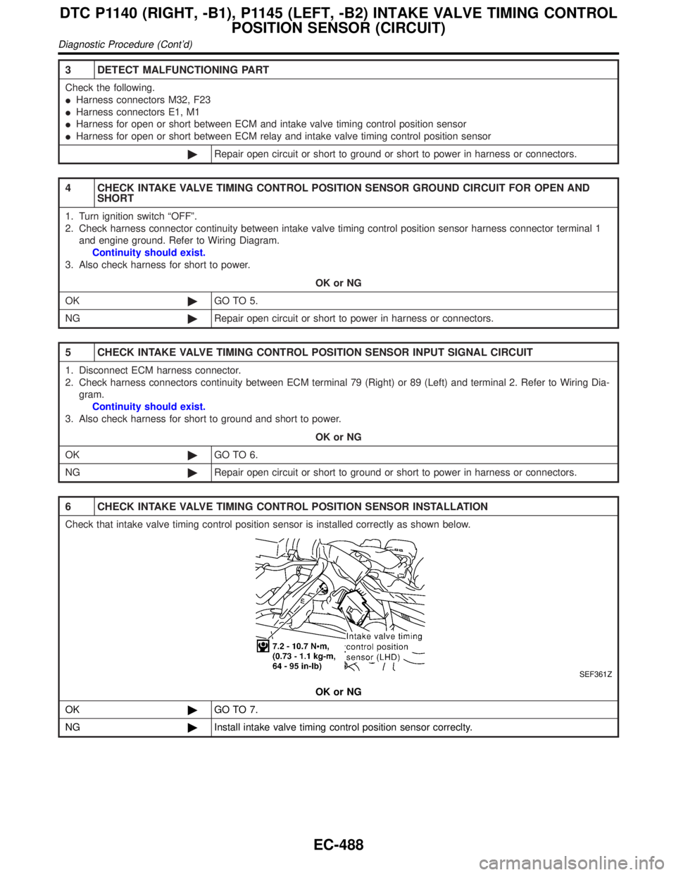
6 CHECK INTAKE VALVE TIMING CONTROL POSITION SENSOR INSTALLATION
Check that intake valve timing control position sensor is installed correctly as shown below.
SEF361Z
OK or NG
OK©GO TO 7.
NG©Install intake valve timing control position sensor correclty.
DTC P1140 (RIGHT, -B1), P1145 (LEFT, -B2) INTAKE VALVE TIMING CONTROL
POSITION SENSOR (CIRCUIT)
Diagnostic Procedure (Cont'd)
EC-488
Page 1032 of 2395

4 CHECK SWIRL CONTROL VALVE CONTROL VACUUM CHECK SWITCH INPUT SIGNAL CIRCUIT FOR
OPEN AND SHORT
1. Disconnect ECM harness connector.
2. Check harness continuity between ECM terminal 55 and swirl control valve control vacuum check switch terminal 1.
Refer to Wiring Diagram.
Continuity should exist.
3. Also check harness for short to ground and short to power.
OK or NG
OK©GO TO 5.
NG©Repair open circuit, short to ground or short to power in harness connectors.
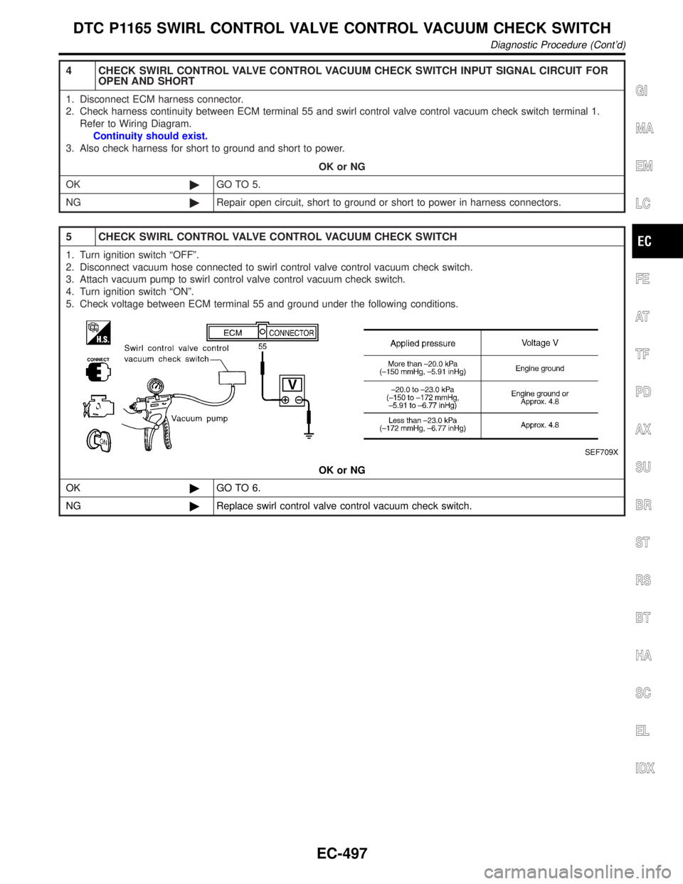
5 CHECK SWIRL CONTROL VALVE CONTROL VACUUM CHECK SWITCH
1. Turn ignition switch ªOFFº.
2. Disconnect vacuum hose connected to swirl control valve control vacuum check switch.
3. Attach vacuum pump to swirl control valve control vacuum check switch.
4. Turn ignition switch ªONº.
5. Check voltage between ECM terminal 55 and ground under the following conditions.
SEF709X
OK or NG
OK©GO TO 6.
NG©Replace swirl control valve control vacuum check switch.
GI
MA
EM
LC
FE
AT
TF
PD
AX
SU
BR
ST
RS
BT
HA
SC
EL
IDX
DTC P1165 SWIRL CONTROL VALVE CONTROL VACUUM CHECK SWITCH
Diagnostic Procedure (Cont'd)
EC-497
Page 1034 of 2395

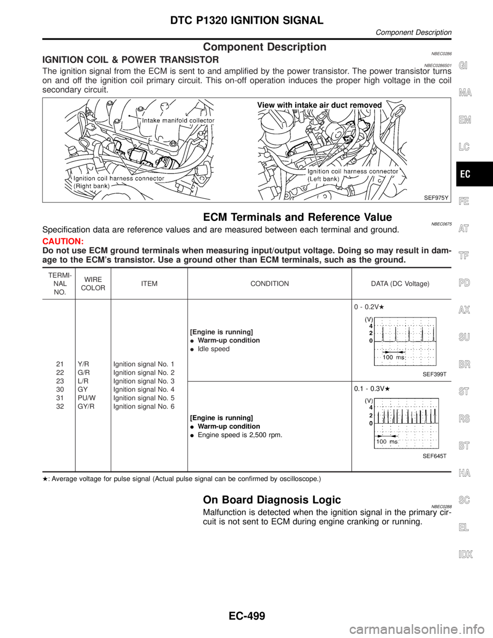
Component DescriptionNBEC0286IGNITION COIL & POWER TRANSISTORNBEC0286S01The ignition signal from the ECM is sent to and amplified by the power transistor. The power transistor turns
on and off the ignition coil primary circuit. This on-off operation induces the proper high voltage in the coil
secondary circuit.
SEF975Y
ECM Terminals and Reference ValueNBEC0675Specification data are reference values and are measured between each terminal and ground.
CAUTION:
Do not use ECM ground terminals when measuring input/output voltage. Doing so may result in dam-
age to the ECM's transistor. Use a ground other than ECM terminals, such as the ground.
TERMI-
NAL
NO.WIRE
COLORITEM CONDITION DATA (DC Voltage)
21
22
23
30
31
32Y/R
G/R
L/R
GY
PU/W
GY/RIgnition signal No. 1
Ignition signal No. 2
Ignition signal No. 3
Ignition signal No. 4
Ignition signal No. 5
Ignition signal No. 6[Engine is running]
IWarm-up condition
IIdle speed0 - 0.2VH
SEF399T
[Engine is running]
IWarm-up condition
IEngine speed is 2,500 rpm.0.1 - 0.3VH
SEF645T
H: Average voltage for pulse signal (Actual pulse signal can be confirmed by oscilloscope.)
On Board Diagnosis LogicNBEC0288Malfunction is detected when the ignition signal in the primary cir-
cuit is not sent to ECM during engine cranking or running.
GI
MA
EM
LC
FE
AT
TF
PD
AX
SU
BR
ST
RS
BT
HA
SC
EL
IDX
DTC P1320 IGNITION SIGNAL
Component Description
EC-499