2001 INFINITI QX4 turn signal
[x] Cancel search: turn signalPage 918 of 2395

SEF194Y
SEF340X
WITH CONSULT-IINBEC0239S011) Start engine and warm it up to normal operating temperature.
2) Turn ignition switch ªOFFº and wait at least 10 seconds.
3) Turn ignition switch ªONº.
4) Select ªDATA MONITORº mode with CONSULT-II.
5) Make sure that ªFUEL T/TEMP SEº is more than 0ÉC (32ÉF).
6) Start engine and wait at least 20 seconds.
7) If 1st trip DTC is detected, go to ªDiagnostic Procedureº,
EC-385.
WITH GSTNBEC0239S021) Start engine and warm it up to normal operating temperature.
2) Check that voltage between ECM terminal 92 (Fuel tank tem-
perature sensor signal) and ground is less than 4.2V.
3) Turn ignition switch ªOFFº and wait at least 10 seconds.
4) Start engine and wait at least 20 seconds.
5) Select ªMODE 7º with GST.
6) If 1st trip DTC is detected, go to ªDiagnostic Procedureº,
EC-385.
GI
MA
EM
LC
FE
AT
TF
PD
AX
SU
BR
ST
RS
BT
HA
SC
EL
IDX
DTC P0450 EVAPORATIVE EMISSION (EVAP) CONTROL SYSTEM PRESSURE
SENSOR
DTC Confirmation Procedure (Cont'd)
EC-383
Page 942 of 2395

SEF018S
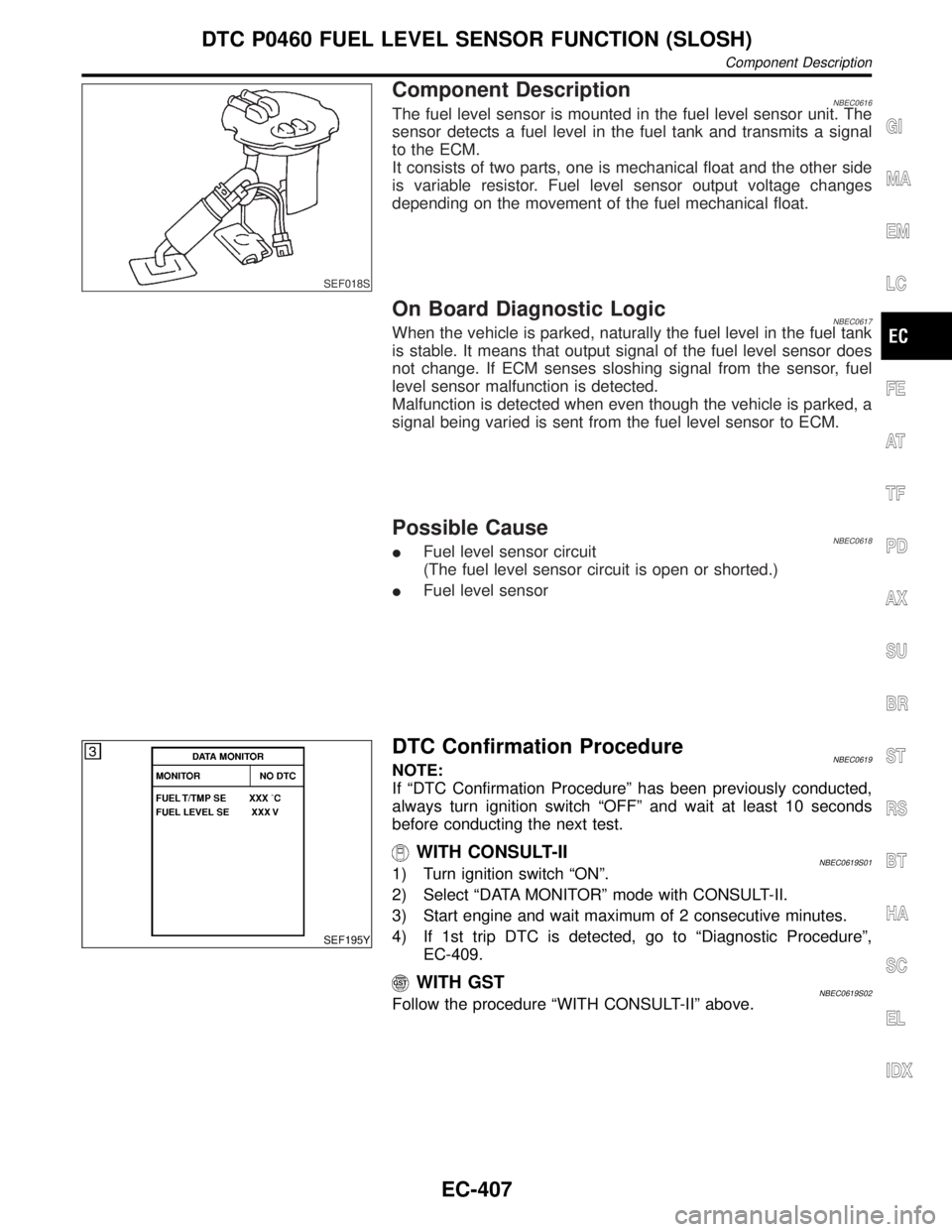
Component DescriptionNBEC0616The fuel level sensor is mounted in the fuel level sensor unit. The
sensor detects a fuel level in the fuel tank and transmits a signal
to the ECM.
It consists of two parts, one is mechanical float and the other side
is variable resistor. Fuel level sensor output voltage changes
depending on the movement of the fuel mechanical float.
On Board Diagnostic LogicNBEC0617When the vehicle is parked, naturally the fuel level in the fuel tank
is stable. It means that output signal of the fuel level sensor does
not change. If ECM senses sloshing signal from the sensor, fuel
level sensor malfunction is detected.
Malfunction is detected when even though the vehicle is parked, a
signal being varied is sent from the fuel level sensor to ECM.
Possible CauseNBEC0618IFuel level sensor circuit
(The fuel level sensor circuit is open or shorted.)
IFuel level sensor
SEF195Y
DTC Confirmation ProcedureNBEC0619NOTE:
If ªDTC Confirmation Procedureº has been previously conducted,
always turn ignition switch ªOFFº and wait at least 10 seconds
before conducting the next test.
WITH CONSULT-IINBEC0619S011) Turn ignition switch ªONº.
2) Select ªDATA MONITORº mode with CONSULT-II.
3) Start engine and wait maximum of 2 consecutive minutes.
4) If 1st trip DTC is detected, go to ªDiagnostic Procedureº,
EC-409.
WITH GSTNBEC0619S02Follow the procedure ªWITH CONSULT-IIº above.
GI
MA
EM
LC
FE
AT
TF
PD
AX
SU
BR
ST
RS
BT
HA
SC
EL
IDX
DTC P0460 FUEL LEVEL SENSOR FUNCTION (SLOSH)
Component Description
EC-407
Page 944 of 2395

Diagnostic Procedure=NBEC0621
1 CHECK FUEL LEVEL SENSOR POWER SUPPLY CIRCUIT
1. Turn ignition switch ªOFFº.
2. Disconnect fuel level sensor unit harness connector.
3. Turn ignition switch ªONº.
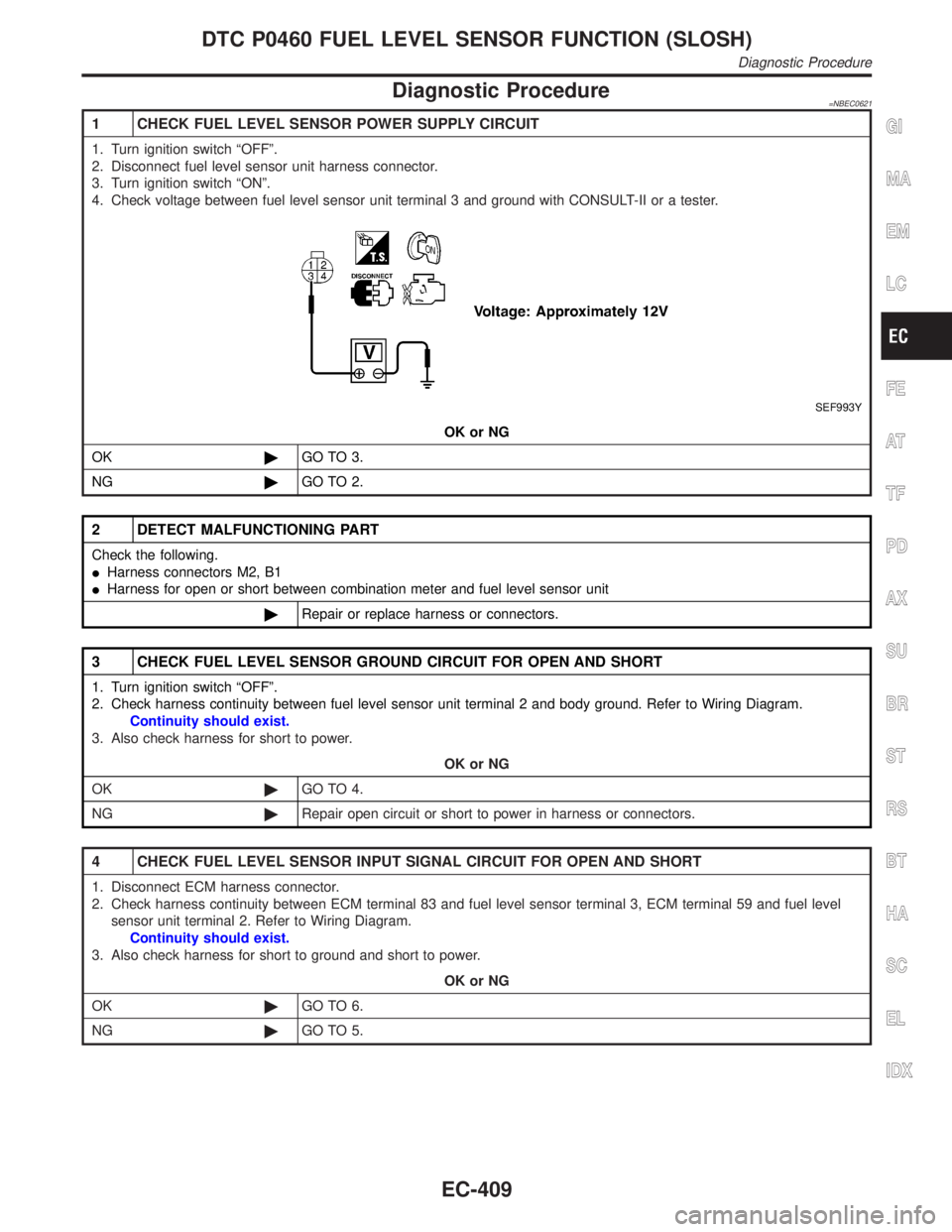
4. Check voltage between fuel level sensor unit terminal 3 and ground with CONSULT-II or a tester.
SEF993Y
OK or NG
OK©GO TO 3.
NG©GO TO 2.
2 DETECT MALFUNCTIONING PART
Check the following.
IHarness connectors M2, B1
IHarness for open or short between combination meter and fuel level sensor unit
©Repair or replace harness or connectors.
3 CHECK FUEL LEVEL SENSOR GROUND CIRCUIT FOR OPEN AND SHORT
1. Turn ignition switch ªOFFº.
2. Check harness continuity between fuel level sensor unit terminal 2 and body ground. Refer to Wiring Diagram.
Continuity should exist.
3. Also check harness for short to power.
OK or NG
OK©GO TO 4.
NG©Repair open circuit or short to power in harness or connectors.
4 CHECK FUEL LEVEL SENSOR INPUT SIGNAL CIRCUIT FOR OPEN AND SHORT
1. Disconnect ECM harness connector.
2. Check harness continuity between ECM terminal 83 and fuel level sensor terminal 3, ECM terminal 59 and fuel level
sensor unit terminal 2. Refer to Wiring Diagram.
Continuity should exist.
3. Also check harness for short to ground and short to power.
OK or NG
OK©GO TO 6.
NG©GO TO 5.
GI
MA
EM
LC
FE
AT
TF
PD
AX
SU
BR
ST
RS
BT
HA
SC
EL
IDX
DTC P0460 FUEL LEVEL SENSOR FUNCTION (SLOSH)
Diagnostic Procedure
EC-409
Page 947 of 2395

5) Turn ignition switch ªOFFº and wait at least 10 seconds then
turn ªONº.
6) Select ªFUEL LEVEL SEº in ªDATA MONITORº mode with
CONSULT-II.
7) Check ªFUEL LEVEL SEº output voltage and note it.
8) Select ªFUEL PUMPº in ªACTIVE TESTº mode with CON-
SULT-II.
9) Touch ªONº and drain fuel approximately 30(7-7/8 US gal,
6-5/8 Imp gal) and stop it.
10) Fill fuel into the fuel tank for 30(7-7/8 US gal, 6-5/8 Imp gal).
11) Check ªFUEL LEVEL SEº output voltage and note it.
12) Check ªFUEL LEVEL SEº output voltage and confirm whether
the voltage changes more than 0.03V during step 7 to 11.
If NG, check the fuel level sensor, refer to EL-108, ªFUEL
LEVEL SENSOR UNIT CHECKº.
SEF615X
WITH GSTNBEC0625S02NOTE:
Start from step 11, if it is possible to confirm that the fuel
cannot be drained by 30(7-7/8 US gal, 6-5/8 Imp gal) in
advance.
1) Prepare a fuel container and a spare hose.
2) Release fuel pressure from fuel line, refer to ªFuel Pressure
Releaseº, EC-39.
3) Remove the fuel feed hose on the fuel level sensor unit.
4) Connect a spare fuel hose where the fuel feed hose was
removed.
5) Turn ignition switch ªOFFº.
6) Set voltmeters probe between ECM terminal 83 (fuel level
sensor signal) and ground.
7) Turn ignition switch ªONº.
8) Check voltage between ECM terminal 83 and ground and note
it.
9) Drain fuel by 30(7-7/8 US gal, 6-5/8 Imp gal) from the fuel
tank using proper equipment.
10) Fill fuel into the fuel tank for 30(7-7/8 US gal, 6-5/8 Imp gal).
11) Confirm that the voltage between ECM terminal 83 and ground
changes more than 0.03V during step8-10.
If NG, check component of fuel level sensor, refer to EL-108,
ªFUEL LEVEL SENSOR UNIT CHECKº.
DTC P0461 FUEL LEVEL SENSOR FUNCTION
Overall Function Check (Cont'd)
EC-412
Page 948 of 2395

SEF018S
Component DescriptionNBEC0626The fuel level sensor is mounted in the fuel level sensor unit. The
sensor detects a fuel level in the fuel tank and transmits a signal
to the ECM.
It consists of two parts, one is mechanical float and the other side
is variable resistor. Fuel level sensor output voltage changes
depending on the movement of the fuel mechanical float.
On Board Diagnostic LogicNBEC0627ECM receives two signals from the fuel level sensor circuit.
One is fuel level sensor power supply circuit, and the other is fuel
level sensor ground circuit.
This diagnosis indicates the former, to detect open or short circuit
malfunction.
Malfunction is detected when an excessively low or high voltage is
sent from the sensor is sent to ECM.
Possible CauseNBEC0628IFuel level sensor circuit
(The fuel level sensor circuit is open or shorted.)
IFuel level sensor
DTC Confirmation ProcedureNBEC0629NOTE:
If ªDTC Confirmation Procedureº has been previously conducted,
always turn ignition switch ªOFFº and wait at least 10 seconds
before conducting the next test.
TESTING CONDITION:
Before performing the following procedure, confirm that bat-
tery voltage is more than 11V at ignition switch ªONº.
SEF195Y
WITH CONSULT-IINBEC0629S011) Turn ignition switch ªONº.
2) Select ªDATA MONITORº mode with CONSULT-II.
3) Wait at least 5 seconds.
4) If 1st trip DTC is detected, go to ªDiagnostic Procedureº,
EC-415.
WITH GSTNBEC0629S02Follow the procedure ªWITH CONSULT-IIº above.
GI
MA
EM
LC
FE
AT
TF
PD
AX
SU
BR
ST
RS
BT
HA
SC
EL
IDX
DTC P0464 FUEL LEVEL SENSOR CIRCUIT
Component Description
EC-413
Page 953 of 2395

Possible CauseNBEC0514IHarness or connector
(The vehicle speed sensor circuit is open or shorted.)
IVehicle speed sensor
DTC Confirmation ProcedureNBEC0245CAUTION:
Always drive vehicle at a safe speed.
NOTE:
If ªDTC Confirmation Procedureº has been previously conducted,
always turn ignition switch ªOFFº and wait at least 10 seconds
before conducting the next test.
TESTING CONDITION:
Steps 1 and 2 may be conducted with the drive wheels lifted
in the shop or by driving the vehicle. If a road test is expected
to be easier, it is unnecessary to lift the vehicle.
SEF196Y
WITH CONSULT-IINBEC0245S011) Start engine (TCS switch ªOFFº).
2) Read ªVHCL SPEED SEº in ªDATA MONITORº mode with
CONSULT-II. The vehicle speed on CONSULT-II should
exceed 10 km/h (6 MPH) when rotating wheels with suitable
gear position.
If NG, go to ªDiagnostic Procedureº, EC-421.
If OK, go to following step.
3) Select ªDATA MONITORº mode with CONSULT-II.
4) Warm engine up to normal operating temperature.
5) Maintain the following conditions for at least 10 consecutive
seconds.
ENG SPEED 1,800 - 6,000 rpm
COOLAN TEMP/S More than 70ÉC (158ÉF)
B/FUEL SCHDL 5.5 - 14.0 msec
Selector lever Suitable position
PW/ST SIGNAL OFF
6) If 1st trip DTC is detected, go to ªDiagnostic Procedureº,
EC-421.
Overall Function CheckNBEC0246Use this procedure to check the overall function of the vehicle
speed sensor circuit. During this check, a 1st trip DTC might not
be confirmed.
WITH GSTNBEC0246S011) Lift up drive wheels.
2) Start engine.
3) Read vehicle speed sensor signal in ªMODE 1º with GST.
The vehicle speed sensor on GST should be able to exceed
DTC P0500 VEHICLE SPEED SENSOR (VSS)
Possible Cause
EC-418
Page 956 of 2395

Diagnostic ProcedureNBEC0248
1 CHECK VEHICLE SPEED SENSOR INPUT SIGNAL CIRCUIT FOR OPEN AND SHORT
1. Turn ignition switch ªOFFº.
2. Disconnect ECM harness connector and combination meter harness connector.
3. Check harness continuity between ECM terminal 86 and combination meter terminal 13.
Refer to Wiring Diagram.
Continuity should exist.
4. Also check harness for short to power.
OK or NG
OK©GO TO 3.
NG©GO TO 2.
2 DETECT MALFUNCTIONING PART
Check the following.
IHarness connectors M32, F23
IHarness for open or short between ECM and combination meter
©Repair open circuit or short to ground or short to power in harness or connectors.
3 CHECK SPEEDOMETER FUNCTION
Make sure that speedometer functions properly.
OK or NG
OK©GO TO 5.
NG©GO TO 4.
4 CHECK SPEEDOMETER CIRCUIT FOR OPEN AND SHORT
Check the following.
IHarness connectors M70, B50
IHarness for open or short between combination meter and vehicle speed sensor
IHarness for open or short between vehicle speed sensor and ECM
OK or NG
OK©Check combination meter and vehicle speed sensor. Refer to EL section.
NG©Repair open circuit or short to ground or short to power in harness or connectors.
5 CHECK INTERMITTENT INCIDENT
Refer to ªTROUBLE DIAGNOSIS FOR INTERMITTENT INCIDENTº, EC-140.
©INSPECTION END
GI
MA
EM
LC
FE
AT
TF
PD
AX
SU
BR
ST
RS
BT
HA
SC
EL
IDX
DTC P0500 VEHICLE SPEED SENSOR (VSS)
Diagnostic Procedure
EC-421
Page 957 of 2395

DescriptionNBEC0249SYSTEM DESCRIPTIONNBEC0249S01
Sensor Input Signal to ECMECM func-
tionActuator
Crankshaft position sensor (POS) Engine speed (POS signal)
Idle air
controlIACV-AAC valve Crankshaft position sensor (REF) Engine speed (REF signal)
Mass air flow sensor Amount of intake air
Engine coolant temperature sensor Engine coolant temperature
Ignition switch Start signal
Throttle position sensor Throttle position
Park/neutral position (PNP) switch Park/neutral position
Air conditioner switch Air conditioner operation
Power steering oil pressure switch Power steering load signal
Battery Battery voltage
Vehicle speed sensor Vehicle speed
Ambient air temperature switch Ambient air temperature
Intake air temperature sensor Intake air temperature
Absolute pressure sensor Ambient barometic pressure
This system automatically controls engine idle speed to a specified
level. Idle speed is controlled through fine adjustment of the
amount of air which by-passes the throttle valve via IACV-AAC
valve. The IACV-AAC valve changes the opening of the air by-pass
passage to control the amount of auxiliary air. This valve is actu-
ated by a step motor built into the valve, which moves the valve in
the axial direction in steps corresponding to the ECM output sig-
nals. One step of IACV-AAC valve movement causes the respec-
tive opening of the air by-pass passage. (i.e. when the step
advances, the opening is enlarged.) The opening of the valve is
varied to allow for optimum control of the engine idling speed. The
crankshaft position sensor (POS) detects the actual engine speed
and sends a signal to the ECM. The ECM then controls the step
position of the IACV-AAC valve so that engine speed coincides with
the target value memorized in ECM. The target engine speed is the
lowest speed at which the engine can operate steadily. The opti-
mum value stored in the ECM is determined by takig into consid-
eration various engine conditions, such as during warm up,
deceleration, and engine load (air conditioner, power steering and
cooling fan operation).
SEF765P
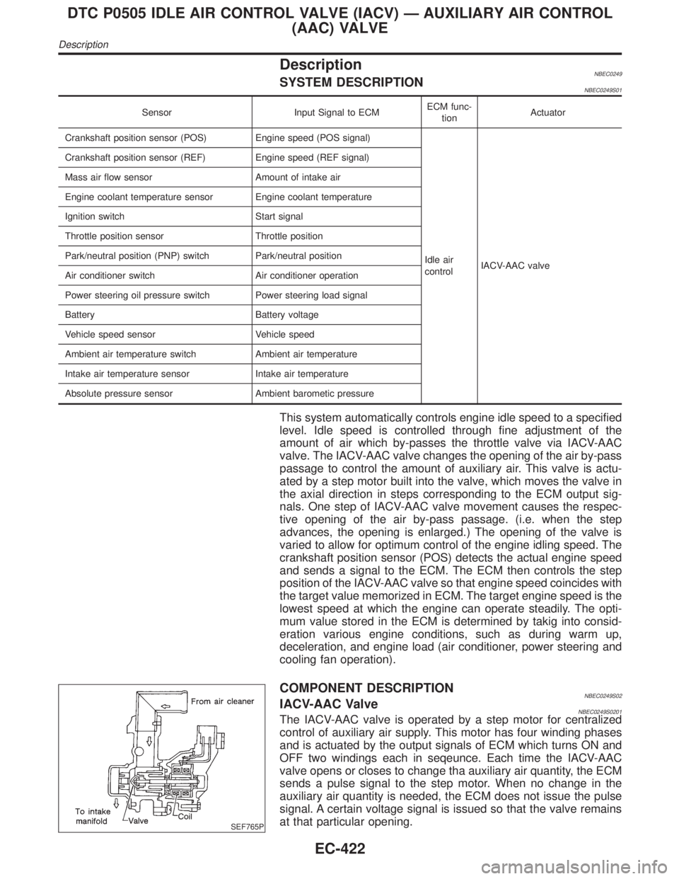
COMPONENT DESCRIPTIONNBEC0249S02IACV-AAC ValveNBEC0249S0201The IACV-AAC valve is operated by a step motor for centralized
control of auxiliary air supply. This motor has four winding phases
and is actuated by the output signals of ECM which turns ON and
OFF two windings each in seqeunce. Each time the IACV-AAC
valve opens or closes to change tha auxiliary air quantity, the ECM
sends a pulse signal to the step motor. When no change in the
auxiliary air quantity is needed, the ECM does not issue the pulse
signal. A certain voltage signal is issued so that the valve remains
at that particular opening.
DTC P0505 IDLE AIR CONTROL VALVE (IACV) Ð AUXILIARY AIR CONTROL
(AAC) VALVE
Description
EC-422