2001 INFINITI QX4 turn signal
[x] Cancel search: turn signalPage 1538 of 2395
IThe vehicle location data is calculated using GPS.
IThe vehicle ignition switch must be turned to the ON position
to obtain the vehicle location. (This is because the system is
in the sleep mode when the ignition switch is OFF.)
IOnce this function starts up, regardless of the ignition switch
position, the system keeps transmitting the vehicle location
until the cancel signal is transmitted from the Communicator
Response Center.
IWhile this function is operating, the operator can covertly moni-
tor what is happening inside the vehicle through the hands-free
microphone.
Alarm NotificationNBEL0180S0405IWhen theft warning system sounds an alarm for more than 7
seconds because of improper access, the alarm signal is
transmitted from the smart entrance control unit to the IVCS
unit, and the system executes automatic dialing to the Com-
municator Response Center.
If the alarm is reset before 7 seconds has elapsed, the
INFINITI Communicator will not place a call to the Communi-
cator Response Center.
IThis function operates regardless of ignition switch position.
IWhile this function is operating, the operator can covertly moni-
tor what is happening inside the vehicle through the hands-free
microphone.
Remote Door UnlockNBEL0180S0406IWhen the door is locked with the key inside the vehicle, the
door can be unlocked by contacting the Communicator
Response Center. (Proof that the person calling is the owner
must be received by the Communicator Response Center.)
IWhen the ignition key is in the ªOFFº position, the system is in
the sleep mode. Therefore, back door outside handle must be
pulled to wake up the system.
ITo perform remote door unlock, call the Communicator
Response Center and follow the operator's instructions.
NOTE:
IWhen the system contacts the Communicator Response
Center, data including the vehicle location is transmitted
to the Communicator Response Center.
ICommunication with the Communicator Response Center
is not completed until the completion signal is transmitted
from the Communicator Response Center. (Any calls to
the Communicator Response Center can only be termi-
nated by Communicator Response Center.)
IFunctions other than alarm notification and remote door
unlock operate while the ignition switch is ON and only for
three minutes after the switch is turned OFF.
IOnce a call to the Communicator Response Center is
made, the communication continues regardless of the
ignition key switch position.
IAll the voice communication with the Communicator
Response Center is made through the hands-free tele-
phone.
IWhen the INFINITI Communicator system is activated, the
handset does not function.
GI
MA
EM
LC
EC
FE
AT
TF
PD
AX
SU
BR
ST
RS
BT
HA
SC
IDX
INFINITI COMMUNICATOR (IVCS)
System Description (Cont'd)
EL-353
Page 1539 of 2395
DATA TRANSMITTINGNBEL0180S05When contact to the Communicator Response Center is made,
vehicle sends electrical data including type of activation (i.e., emer-
gency call or alarm notification), vehicle location, time, etc.
SLEEP/WAKE UP CONTROLNBEL0180S063 minutes after the ignition switch is turned OFF, the system goes
into the SLEEP MODE to save battery power supply. Communica-
tion with Communicator Response Center is not available in the
SLEEP MODE.
To wake up the system, perform either of the following operations.
ITurn Ignition switch ON.
IPull back door outside handle for more than 10 seconds.
(Operation for door unlock function)
SEL532V
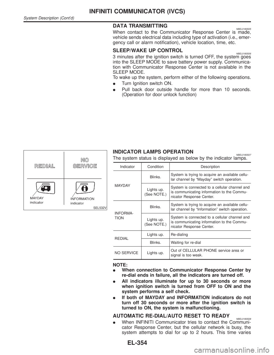
INDICATOR LAMPS OPERATIONNBEL0180S07The system status is displayed as below by the indicator lamps.
Indicator Condition Description
MAYDAYBlinks.System is trying to acquire an available cellu-
lar channel by ªMaydayº switch operation.
Lights up.
(See NOTE.)System is connected to a cellular channel and
is communicating information to the Commu-
nicator Response Center.
INFORMA-
TIONBlinks.System is trying to acquire an available cellu-
lar channel by ªInformationº switch operation.
Lights up.
(See NOTE.)System is connected to a cellular channel and
is communicating information to the Commu-
nicator Response Center.
REDIALLights up. Re-dialing
Blinks. Waiting for re-dial
NO SERVICE Lights up.Out of CELLULAR PHONE service area or
signal is too weak.
NOTE:
IWhen connection to Communicator Response Center by
re-dial ends in failure, all the indicators are turned off.
IAll indicators illuminate for up to 30 seconds or more
when ignition switch is turned from OFF to ON and the
system performs a self check.
IIf both of MAYDAY and INFORMATION indicators do not
turn off 30 seconds or more after the ignition switch is
turned to ON, the system is malfunctioning.
AUTOMATIC RE-DIAL/AUTO RESET TO READYNBEL0180S08IWhen INFINITI Communicator tries to contact the Communi-
cator Response Center, but the cellular network is busy, the
system attempts to dial for up to 2 hours. This time varies
INFINITI COMMUNICATOR (IVCS)
System Description (Cont'd)
EL-354
Page 1540 of 2395
greatly depending on the cellular network and cellular signal
strength. The system resets to ready when the system com-
pletes the dialing attempts. The vehicle owner can press the
button again if he or she still needs to contact the Communi-
cator Response Center.
IINFINITI Communicator automatically redials if communication
between the vehicle owner and Communicator Response Cen-
ter is lost for some reason.
IThe only way for a transmission to be officially terminated is for
the Communicator Response Center to send an end transmis-
sion signal, which turns off the indicator in the switch. (Com-
munication with Communicator Response Center can not be
terminated by the occupant.)
IIf the vehicle owner start the engine during a call, the conver-
sation may be interrupted. When this happens the system may
try to resume transmission once after the engine has been
started.
SEL526V
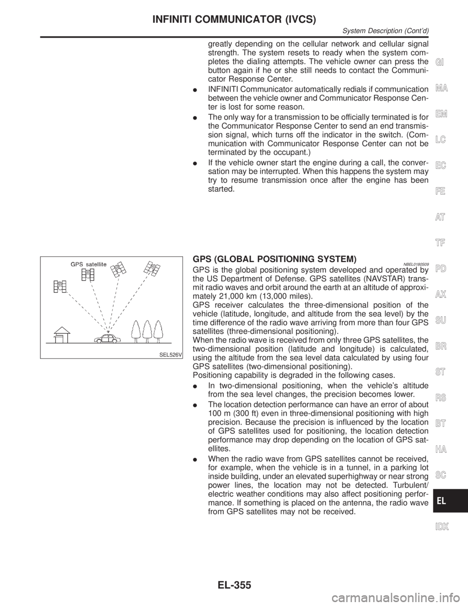
GPS (GLOBAL POSITIONING SYSTEM)NBEL0180S09GPS is the global positioning system developed and operated by
the US Department of Defense. GPS satellites (NAVSTAR) trans-
mit radio waves and orbit around the earth at an altitude of approxi-
mately 21,000 km (13,000 miles).
GPS receiver calculates the three-dimensional position of the
vehicle (latitude, longitude, and altitude from the sea level) by the
time difference of the radio wave arriving from more than four GPS
satellites (three-dimensional positioning).
When the radio wave is received from only three GPS satellites, the
two-dimensional position (latitude and longitude) is calculated,
using the altitude from the sea level data calculated by using four
GPS satellites (two-dimensional positioning).
Positioning capability is degraded in the following cases.
IIn two-dimensional positioning, when the vehicle's altitude
from the sea level changes, the precision becomes lower.
IThe location detection performance can have an error of about
100 m (300 ft) even in three-dimensional positioning with high
precision. Because the precision is influenced by the location
of GPS satellites used for positioning, the location detection
performance may drop depending on the location of GPS sat-
ellites.
IWhen the radio wave from GPS satellites cannot be received,
for example, when the vehicle is in a tunnel, in a parking lot
inside building, under an elevated superhighway or near strong
power lines, the location may not be detected. Turbulent/
electric weather conditions may also affect positioning perfor-
mance. If something is placed on the antenna, the radio wave
from GPS satellites may not be received.
GI
MA
EM
LC
EC
FE
AT
TF
PD
AX
SU
BR
ST
RS
BT
HA
SC
IDX
INFINITI COMMUNICATOR (IVCS)
System Description (Cont'd)
EL-355
Page 1558 of 2395
IVCS SWITCH CHECK=NBEL0184S07
1 CHECK IVCS SWITCH INPUT SIGNAL
1. Turn ignition switch ªONº.
2. Select ªSWITCH MONITORº in ªDATA MONITORº mode.
3. Check each switch signal.
Condition:
When MAYDAY/INFORMATION switch is pushed:
MAYDAY/INFORMATION ON
When MAYDAY/INFORMATION switch is released:
MAYDAY/INFORMATION OFF
NOTE:
When CONSULT-II ªDATA MONITORº mode is operating, INFINITI Communicator does not dial to Communicator
Response Center when the switches are operated.
OK or NG
OK©IVCS switch is OK.
NG©GO TO 2.
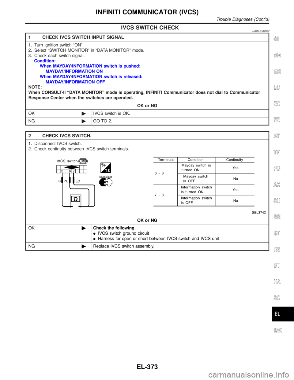
2 CHECK IVCS SWITCH.
1. Disconnect IVCS switch.
2. Check continuity between IVCS switch terminals.
SEL374X
OK or NG
OK©Check the following.
IIVCS switch ground circuit
IHarness for open or short between IVCS switch and IVCS unit
NG©Replace IVCS switch assembly.
GI
MA
EM
LC
EC
FE
AT
TF
PD
AX
SU
BR
ST
RS
BT
HA
SC
IDX
INFINITI COMMUNICATOR (IVCS)
Trouble Diagnoses (Cont'd)
EL-373
Page 1559 of 2395
BACK DOOR HANDLE SWITCH CHECK=NBEL0184S08
1 CHECK BACK DOOR HANDLE SWITCH INPUT SIGNAL
1. Turn ignition switch ON.
2. Select ªSWITCH MONITORº in ªDATA MONITORº mode.
3. Check the switch operation.
Condition:
When back door handle switch is pushed:
DR HANDLE ON
When back door handle switch is released:
DR HANDLE OFF
NOTE:
When CONSULT-II ªDATA MONITORº mode is operating, INFINITI Communicator does not dial to Communicator
Response Center when the switches are operated.
OK or NG
OK©Back door handle switch is OK.
NG©GO TO 2.
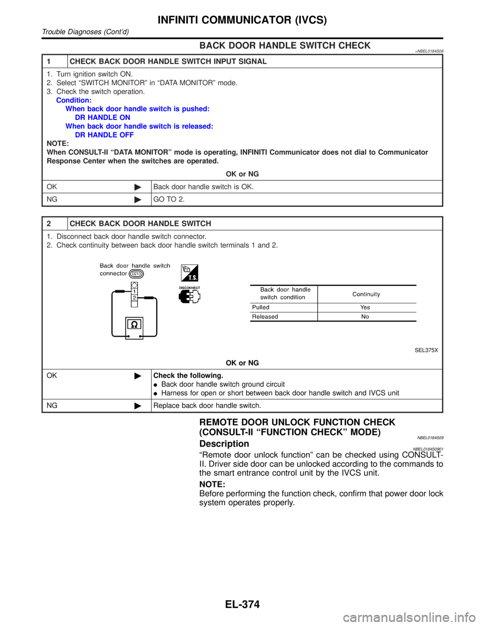
2 CHECK BACK DOOR HANDLE SWITCH
1. Disconnect back door handle switch connector.
2. Check continuity between back door handle switch terminals 1 and 2.
SEL375X
OK or NG
OK©Check the following.
IBack door handle switch ground circuit
IHarness for open or short between back door handle switch and IVCS unit
NG©Replace back door handle switch.
REMOTE DOOR UNLOCK FUNCTION CHECK
(CONSULT-II ªFUNCTION CHECKº MODE)
NBEL0184S09DescriptionNBEL0184S0901ªRemote door unlock functionº can be checked using CONSULT-
II. Driver side door can be unlocked according to the commands to
the smart entrance control unit by the IVCS unit.
NOTE:
Before performing the function check, confirm that power door lock
system operates properly.
INFINITI COMMUNICATOR (IVCS)
Trouble Diagnoses (Cont'd)
EL-374
Page 1582 of 2395
Self-diagnosis ModeNBEL0231APPLICATION ITEMSNBEL0231S01
Mode DescriptionReference
page
Self DiagnosisSelf-diagnosis for display & NAVI control unit, CD-ROM
and GPS antenna connection.EL-398
Confirmation/
adjustmentDisplay Diagnosis Color and gray gradation of display can be checked in
this mode.EL-406
Diagnostic Signals from the Car Several input signals to display & NAVI control unit, can
be monitored in this mode.EL-404
NavigationCheck the map CD-
ROM versionThe version (parts number) of inserted CD-ROM can be
checked in this mode.EL-405
Error history Diagnosis results previously stored in the memory
(before turning ignition switch ON) are displayed in this
mode. Time and location when/where the errors
occurred are also displayed.EL-400
Longitude & Latitude Display the map. Use the joystick to adjust position. Lon-
gitude and latitude will be displayed.EL-407
Adjust the angle Turning angle of the vehicle on the display can be
adjusted in this mode.EL-408
Speed CalibrationUnder ordinary conditions, the navigation system dis-
tance measuring function will automatically compensate
for minute decreases in wheel and tire diameter caused
by tire wear or low pressure. Speed calibration immedi-
ately restores system accuracy in cases such as when
distance calibration is needed because of the use of tire
chains in inclement weather.EL-409
Initialize Location This mode is for initializing the current location. Use
when the vehicle is transported a long distance on a
trailer, etc.EL-433
SEL583X
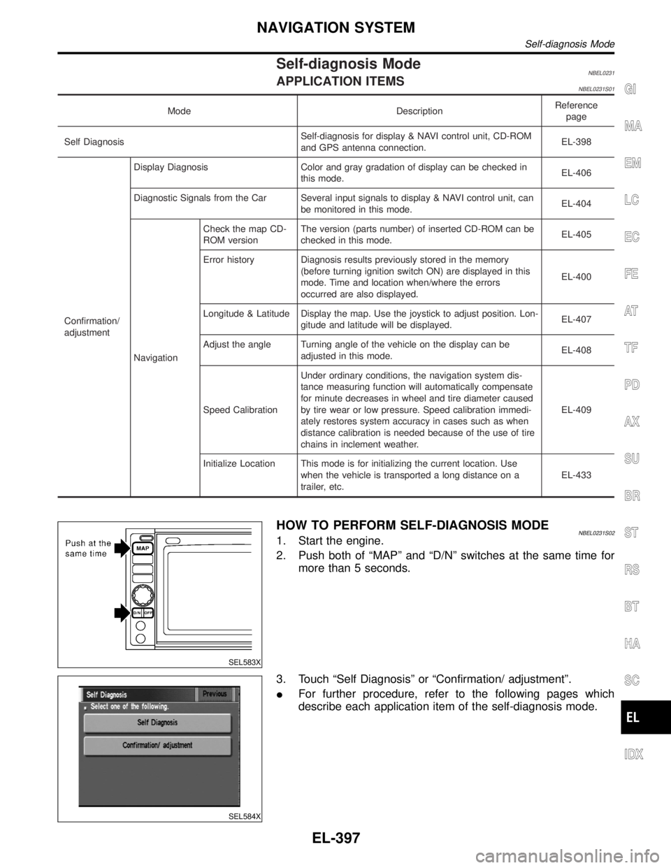
HOW TO PERFORM SELF-DIAGNOSIS MODENBEL0231S021. Start the engine.
2. Push both of ªMAPº and ªD/Nº switches at the same time for
more than 5 seconds.
SEL584X
3. Touch ªSelf Diagnosisº or ªConfirmation/ adjustmentº.
IFor further procedure, refer to the following pages which
describe each application item of the self-diagnosis mode.
GI
MA
EM
LC
EC
FE
AT
TF
PD
AX
SU
BR
ST
RS
BT
HA
SC
IDX
NAVIGATION SYSTEM
Self-diagnosis Mode
EL-397
Page 1602 of 2395
SEL611X
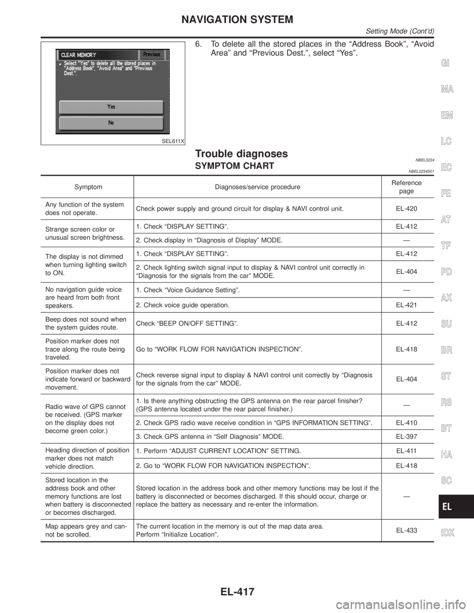
6. To delete all the stored places in the ªAddress Bookº, ªAvoid
Areaº and ªPrevious Dest.º, select ªYesº.
Trouble diagnosesNBEL0234SYMPTOM CHARTNBEL0234S01
Symptom Diagnoses/service procedureReference
page
Any function of the system
does not operate.Check power supply and ground circuit for display & NAVI control unit. EL-420
Strange screen color or
unusual screen brightness.1. Check ªDISPLAY SETTINGº. EL-412
2. Check display in ªDiagnosis of Displayº MODE. Ð
The display is not dimmed
when turning lighting switch
to ON.1. Check ªDISPLAY SETTINGº. EL-412
2. Check lighting switch signal input to display & NAVI control unit correctly in
ªDiagnosis for the signals from the carº MODE.EL-404
No navigation guide voice
are heard from both front
speakers.1. Check ªVoice Guidance Settingº. Ð
2. Check voice guide operation. EL-421
Beep does not sound when
the system guides route.Check ªBEEP ON/OFF SETTINGº. EL-412
Position marker does not
trace along the route being
traveled.Go to ªWORK FLOW FOR NAVIGATION INSPECTIONº. EL-418
Position marker does not
indicate forward or backward
movement.Check reverse signal input to display & NAVI control unit correctly by ªDiagnosis
for the signals from the carº MODE.EL-404
Radio wave of GPS cannot
be received. (GPS marker
on the display does not
become green color.)1. Is there anything obstructing the GPS antenna on the rear parcel finisher?
(GPS antenna located under the rear parcel finisher.)Ð
2. Check GPS radio wave receive condition in ªGPS INFORMATION SETTINGº. EL-410
3. Check GPS antenna in ªSelf Diagnosisº MODE. EL-397
Heading direction of position
marker does not match
vehicle direction.1. Perform ªADJUST CURRENT LOCATIONº SETTING. EL-411
2. Go to ªWORK FLOW FOR NAVIGATION INSPECTIONº. EL-418
Stored location in the
address book and other
memory functions are lost
when battery is disconnected
or becomes discharged.Stored location in the address book and other memory functions may be lost if the
battery is disconnected or becomes discharged. If this should occur, charge or
replace the battery as necessary and re-enter the information.Ð
Map appears grey and can-
not be scrolled.The current location in the memory is out of the map data area.
Perform ªInitialize Locationº.EL-433
GI
MA
EM
LC
EC
FE
AT
TF
PD
AX
SU
BR
ST
RS
BT
HA
SC
IDX
NAVIGATION SYSTEM
Setting Mode (Cont'd)
EL-417
Page 1606 of 2395
VOICE GUIDE OPERATION CHECK=NBEL0234S05
1 PRELIMINARY CHECK
1. Turn ignition switch to ACC position.
2. Insert the music CD into the radio and CD player.
3. Try to play the music CD.
Is the sound emitted from all speakers?
YesorNo
Ye s©GO TO 2.
No©Repair or replace audio system.
Refer to ªAUDIOº in EL-160.
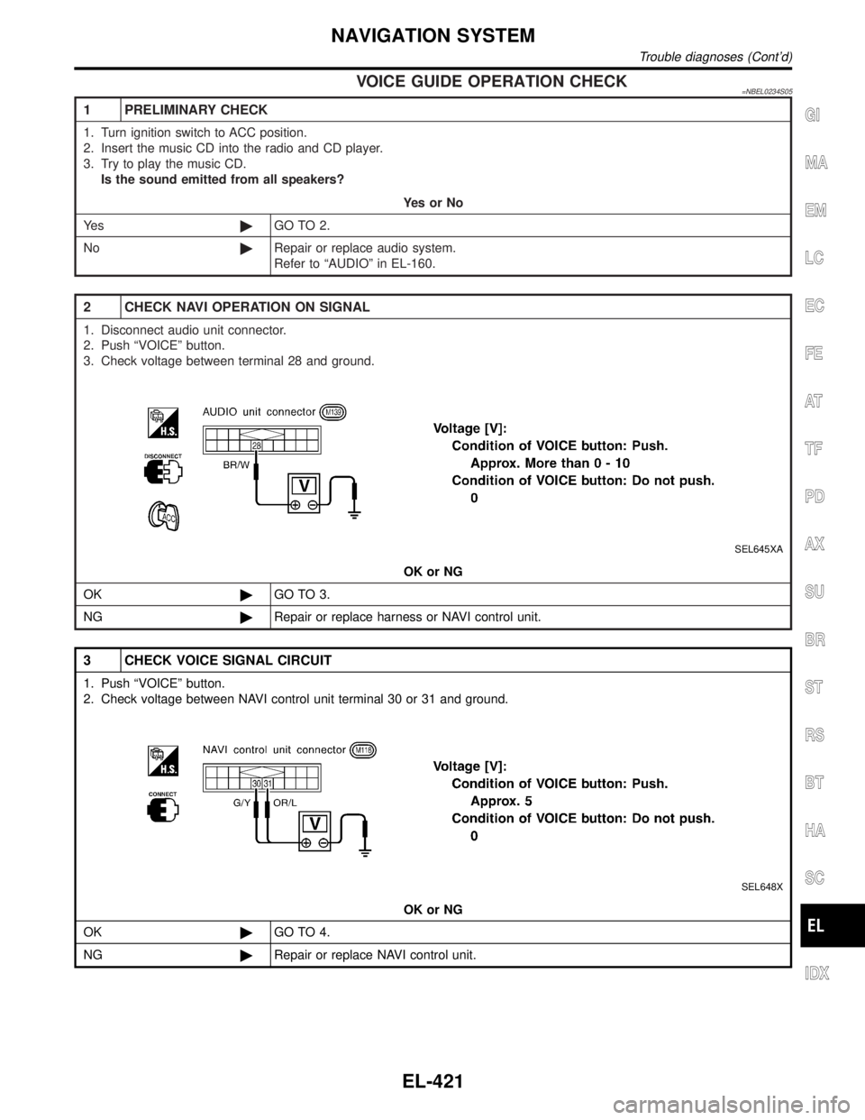
2 CHECK NAVI OPERATION ON SIGNAL
1. Disconnect audio unit connector.
2. Push ªVOICEº button.
3. Check voltage between terminal 28 and ground.
SEL645XA
OK or NG
OK©GO TO 3.
NG©Repair or replace harness or NAVI control unit.
3 CHECK VOICE SIGNAL CIRCUIT
1. Push ªVOICEº button.
2. Check voltage between NAVI control unit terminal 30 or 31 and ground.
SEL648X
OK or NG
OK©GO TO 4.
NG©Repair or replace NAVI control unit.
GI
MA
EM
LC
EC
FE
AT
TF
PD
AX
SU
BR
ST
RS
BT
HA
SC
IDX
NAVIGATION SYSTEM
Trouble diagnoses (Cont'd)
EL-421