2001 INFINITI QX4 turn signal
[x] Cancel search: turn signalPage 1819 of 2395
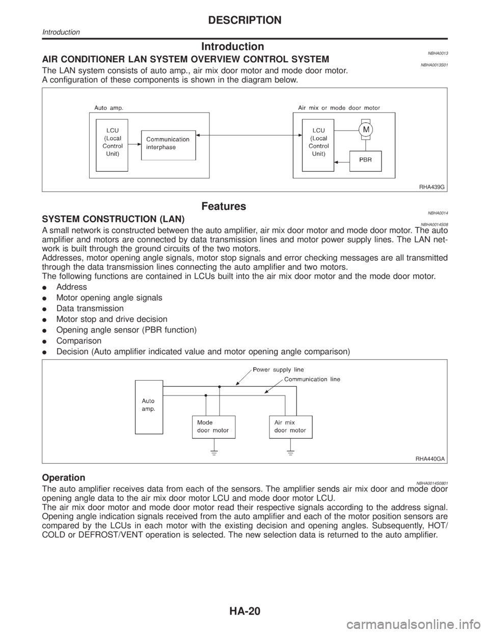
IntroductionNBHA0013AIR CONDITIONER LAN SYSTEM OVERVIEW CONTROL SYSTEMNBHA0013S01The LAN system consists of auto amp., air mix door motor and mode door motor.
A configuration of these components is shown in the diagram below.
RHA439G
FeaturesNBHA0014SYSTEM CONSTRUCTION (LAN)NBHA0014S08A small network is constructed between the auto amplifier, air mix door motor and mode door motor. The auto
amplifier and motors are connected by data transmission lines and motor power supply lines. The LAN net-
work is built through the ground circuits of the two motors.
Addresses, motor opening angle signals, motor stop signals and error checking messages are all transmitted
through the data transmission lines connecting the auto amplifier and two motors.
The following functions are contained in LCUs built into the air mix door motor and the mode door motor.
IAddress
IMotor opening angle signals
IData transmission
IMotor stop and drive decision
IOpening angle sensor (PBR function)
IComparison
IDecision (Auto amplifier indicated value and motor opening angle comparison)
RHA440GA
OperationNBHA0014S0801The auto amplifier receives data from each of the sensors. The amplifier sends air mix door and mode door
opening angle data to the air mix door motor LCU and mode door motor LCU.
The air mix door motor and mode door motor read their respective signals according to the address signal.
Opening angle indication signals received from the auto amplifier and each of the motor position sensors are
compared by the LCUs in each motor with the existing decision and opening angles. Subsequently, HOT/
COLD or DEFROST/VENT operation is selected. The new selection data is returned to the auto amplifier.
DESCRIPTION
Introduction
HA-20
Page 1876 of 2395
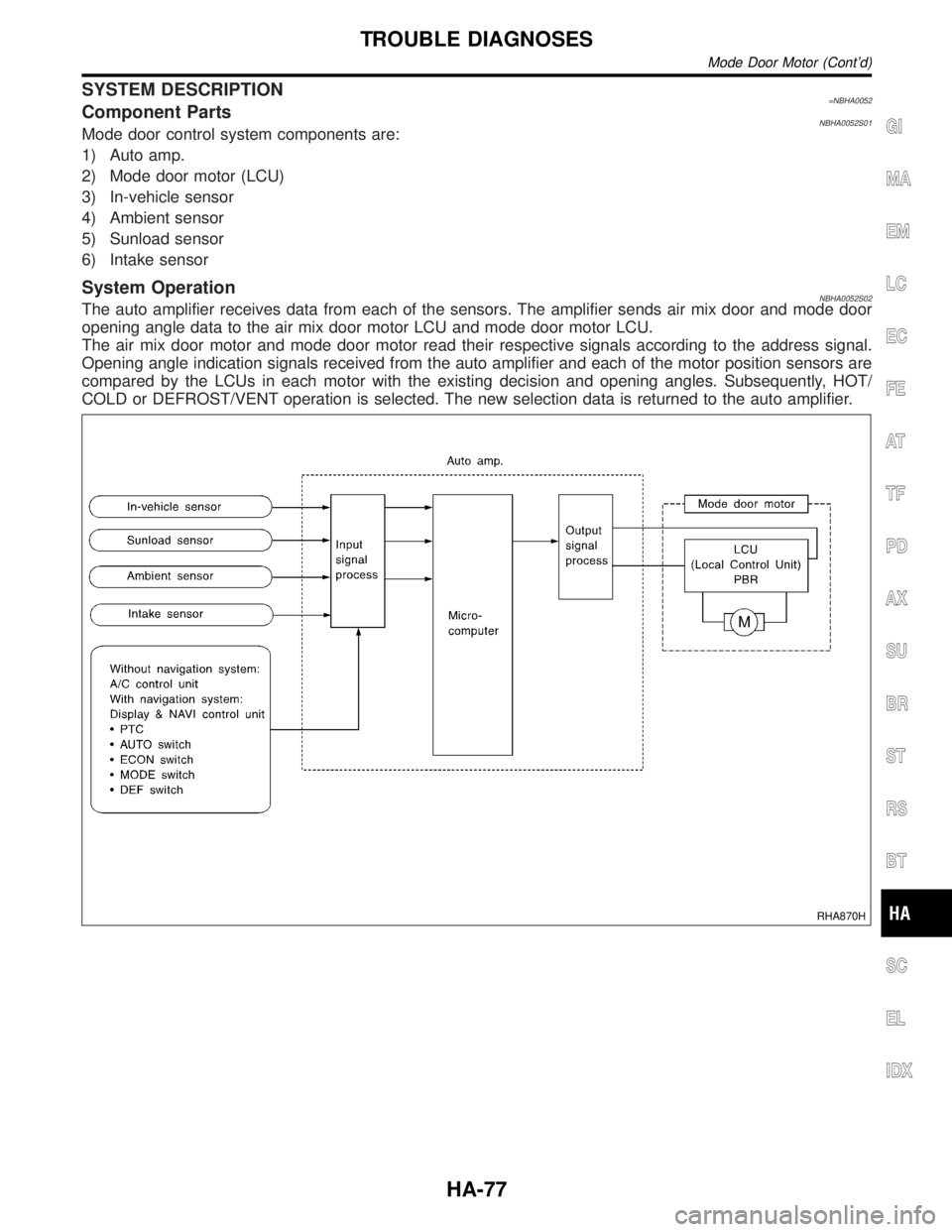
SYSTEM DESCRIPTION=NBHA0052Component PartsNBHA0052S01Mode door control system components are:
1) Auto amp.
2) Mode door motor (LCU)
3) In-vehicle sensor
4) Ambient sensor
5) Sunload sensor
6) Intake sensor
System OperationNBHA0052S02The auto amplifier receives data from each of the sensors. The amplifier sends air mix door and mode door
opening angle data to the air mix door motor LCU and mode door motor LCU.
The air mix door motor and mode door motor read their respective signals according to the address signal.
Opening angle indication signals received from the auto amplifier and each of the motor position sensors are
compared by the LCUs in each motor with the existing decision and opening angles. Subsequently, HOT/
COLD or DEFROST/VENT operation is selected. The new selection data is returned to the auto amplifier.
RHA870H
GI
MA
EM
LC
EC
FE
AT
TF
PD
AX
SU
BR
ST
RS
BT
SC
EL
IDX
TROUBLE DIAGNOSES
Mode Door Motor (Cont'd)
HA-77
Page 1883 of 2395
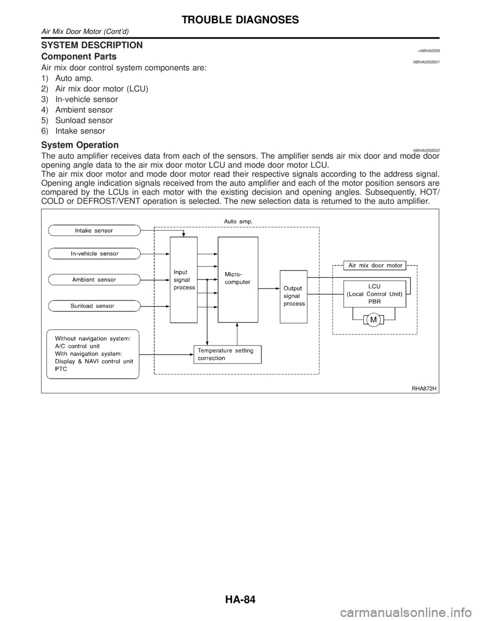
SYSTEM DESCRIPTION=NBHA0059Component PartsNBHA0059S01Air mix door control system components are:
1) Auto amp.
2) Air mix door motor (LCU)
3) In-vehicle sensor
4) Ambient sensor
5) Sunload sensor
6) Intake sensor
System OperationNBHA0059S02The auto amplifier receives data from each of the sensors. The amplifier sends air mix door and mode door
opening angle data to the air mix door motor LCU and mode door motor LCU.
The air mix door motor and mode door motor read their respective signals according to the address signal.
Opening angle indication signals received from the auto amplifier and each of the motor position sensors are
compared by the LCUs in each motor with the existing decision and opening angles. Subsequently, HOT/
COLD or DEFROST/VENT operation is selected. The new selection data is returned to the auto amplifier.
RHA872H
TROUBLE DIAGNOSES
Air Mix Door Motor (Cont'd)
HA-84
Page 1905 of 2395

RHA094GB
SYSTEM DESCRIPTION=NBHA0066Auto amplifier controls compressor operation by ambient tempera-
ture and signal from ECM.
Low Temperature Protection ControlNBHA0066S01Auto amplifier will turn the compressor ªONº or ªOFFº as deter-
mined by a signal detected by ambient sensor.
When ambient temperatures are greater than ±2ÉC (28ÉF), the
compressor turns ªONº. The compressor turns ªOFFº when ambi-
ent temperatures are less than þ5ÉC (23ÉF).
RHA877H
DIAGNOSTIC PROCEDURENBHA0067SYMPTOM: Magnet clutch does not engage when AUTO
switch is ON.
1 CHECK POWER SUPPLY FOR COMPRESSOR
Disconnect compressor harness connector. Do approx. 12 volts exist between compressor harness terminal No. 1 and
body ground?
RHA096G
YesorNo
Ye s©Check magnet clutch coil.
1. If NG, replace magnet clutch. Refer to HA-150.
2. Go to self-diagnosis step-by-step procedure (HA-45) and perform self-diagnosis STEP
4.
Confirm that magnet clutch operation is normal.
No©Disconnect A/C relay. And GO TO 2.
TROUBLE DIAGNOSES
Magnet Clutch (Cont'd)
HA-106
Page 1966 of 2395
Propeller shaft greasing .................................MA-23
Propeller shaft inspection ..............................MA-23
Propeller shaft on vehicle service ....................PD-6
Propeller shaft vibration ...................................PD-6
PST/SW - Wiring diagram ............................EC-635
R
Rack retainer adjustment ..................................ST-8
Radiator ....................................................LC-19, 21
Radio - See Audio.........................................EL-160
Rear air spoiler ...............................................BT-35
Rear axle ........................................................AX-17
Rear bumper ...................................................BT-15
Rear case (Transfer) .....................................TF-123
Rear combination lamp removal and
installation ...................................................BT-35
Rear cover packing replacement diff. ............PD-16
Rear door ........................................................BT-20
Rear drum brake ............................................BR-26
Rear heated oxygen sensor
(HO2S) .............................EC-247, 257, 267, 277
Rear heated oxygen sensor (HO2S)
heater ........................................................EC-286
Rear seat ........................................................BT-44
Rear seat belt ...................................................RS-5
Rear side window ...........................................BT-55
Rear suspension ............................................SU-15
Rear washer..................................................EL-141
Rear window defogger ..................................EL-151
Rear wiper.....................................................EL-141
REF - Wiring diagram ..................................EC-510
Refregerant pressure sensor ........................HA-111
Refrigerant connection precaution ...................HA-4
Refrigerant discharging evacuating
charging ....................................................HA-144
Refrigerant general precaution.........................HA-3
Refrigerant lines ...........................................HA-154
Refrigerant pressure sensor.........................EC-639
Refrigeration cycle..........................................HA-14
REMOTE - Wiring diagram ...........................EL-168
Removal and installation (A/T) ......................AT-277
Removal and installation (Transfer) ..............TF-119
Reverse clutch...............................................AT-314
Revolution sensor (A/T).................................AT-115
Ring gear diff. inspection .........................PD-23, 47
RO2H-L - Wiring diagram.............................EC-290
RO2H-R - Wiring diagram ............................EC-289
Road wheel size ..............................................GI-44
Roof trim .........................................................BT-32
Room lamp - See Interior lamp ......................EL-88
RRO2LH - Wiring diagram...EC-251, 261, 271, 281
RRO2RH - Wiring diagram ..EC-250, 260, 270, 280
S
SAE J1930 terminology list .............................GI-51
Screw jack .......................................................GI-45Seal - See Exterior .........................................BT-35
SEAT - Wiring diagram .................................EL-181
Seat belt inspection .............................MA-28, RS-7
Seat belt pre-tensioner .....................................RS-3
Seat belt pre-tensioner disposal ....................RS-22
Seat belt, front ..................................................RS-4
Seat belt, rear...................................................RS-5
Seat, front .......................................................BT-41
Seat, rear ........................................................BT-44
Self-diagnosis (Transfer) .................................TF-27
SHIFT - Wiring diagram ................................AT-266
Shift lock system ...........................................AT-265
Shift schedule ................................................AT-356
Shift solenoid valve A (A/T) ..AT-125, 137, 147, 171
Shift solenoid valve B (A/T) ..AT-125, 131, 147, 175
Shock absorber (rear) ....................................SU-18
Side air bag ....................................................RS-21
Side bearing preload (front final drive
4WD) ...........................................................PD-24
Side trim ..........................................................BT-28
Side window - See Rear side window ............BT-55
Smart entrance control unit ..........................EL-319
SMJ (super multiple junction) .......................Foldout
Spare tire size .................................................GI-44
Spark plug replacement .................................MA-19
Speedometer...................................................EL-94
Spiral cable.....................................................RS-17
Spot lamp ........................................................EL-88
Spring (Wheelarch) height ...............................SU-5
SROOF - Wiring diagram .............................EL-174
SRS - See Supplemental Restraint
System ........................................................RS-10
SRS - Wiring diagram ....................................RS-35
S/SIG - Wiring diagram ................................EC-622
Stabilizer bar (front)........................................SU-10
Stabilizer bar (rear) ........................................SU-20
Stall test (A/T) .................................................AT-59
Standardized relay ............................................EL-7
START - Wiring diagram.................................SC-11
Start signal ...................................................EC-621
Starter .............................................................SC-18
Starting system...............................................SC-10
Steering gear, linkage and transfer
gear inspection ...........................................MA-26
Steering linkage ..............................................ST-17
Steering switch................................................EL-30
Steering transfer gear .....................................ST-15
Steering wheel and column.............................ST-11
Steering wheel play ..........................................ST-7
Steering wheel turning force .............................ST-9
Stop lamp ........................................................EL-67
STOP/L - Wiring diagram................................EL-67
Strut (front) .......................................................SU-8
Sub-oil pump (Transfer) ................................TF-131
Sun gear (Transfer).......................................TF-134
Sun roof, electric ...........................................EL-173
Sunload sensor ............................................HA-135
Sunroof............................................................BT-45
Supplemental Restraint System .....................RS-10
Supplemental restraint system - Wiring
diagram .......................................................RS-35
GI
MA
EM
LC
EC
FE
AT
TF
PD
AX
SU
BR
ST
RS
BT
HA
SC
EL
ALPHABETICAL INDEX
IDX-7
Page 1967 of 2395
S/VCSW - Wiring diagram ...........................EC-493
Swirl control valve control solenoid
valve .........................................................EC-458
Swirl control valve control vacuum
check switch .............................................EC-493
SWL/V - Wiring diagram ..............................EC-458
Symbols and abbreviations .............................GI-10
Symptom matrix chart...................................EC-118
System readiness test (SRT) code ................EC-61
T
2-4WD shift solenoid valve............................TF-111
Tachometer .....................................................EL-94
Tail lamp ..........................................................EL-61
TAIL/L - Wiring diagram ..................................EL-63
TCM circuit diagram ........................................AT-13
TCM inspection table ......................................AT-92
TFTS - Wiring diagram .................................EC-311
THEFT - Wiring diagram ...............................EL-300
Theft warning system....................................EL-294
Thermometer .................................................EL-110
Thermostat ......................................................LC-16
Three way catalyst function (Left bank) .......EC-347
Three way catalyst function (Right
bank) .........................................................EC-347
Three way catalyst precautions.........................GI-6
Throttle bodies ...............................................EM-12
Throttle position sensor (TPS) .....................EC-174
Throttle position sensor adjustment .............EC-101
Throttle position switch ...........EC-431, AT-184, 264
Tie-rod .............................................................ST-21
Tie-rod ball joints.............................................ST-21
Tightening torque of standard bolts.................GI-50
Timing chain ...................................................EM-20
Tire rotation ....................................................MA-24
Tire size ...........................................................GI-44
TLID - Wiring diagram ..................................EL-179
Tooth contact (front final drive 4WD) .............PD-29
Tooth contact diff. ...........................................PD-56
Torque converter installation .........................AT-278
Torque convertor clutch solenoid
valve ..................................................AT-152, 161
Tow truck towing ..............................................GI-47
Towing point.....................................................GI-49
TP/SW - Wiring diagram ..............................EC-434
TPS - Wiring diagram...................................EC-180
Transfer control unit inspection table..............TF-55
Transfer dropping resistor .............................TF-112
Transfer fluid replacement (Part time
4WD model) ...............................................MA-22
Transfer fluid temperature sensor .................TF-111
Transfer motor ...............................................TF-117
Transfer motor relay ......................................TF-113
Transfer serial number ....................................GI-43
TRANSMT - Wiring diagram .........................EL-325
Tread-FR&RR (Dimensions)............................GI-43
Trim .................................................................BT-28
Trouble diagnoses ...........................................GI-34
Trunk lid opener, electric...............................EL-178Turbine revolution sensor..............................AT-202
TURN - Wiring diagram ..................................EL-77
Turn signal lamp .............................................EL-75
Two trip detection logic ..................................EC-59
Two-pole lift .....................................................GI-47
U
Under body .....................................................BT-60
V
Vacuum cut valve ...........................................EC-32
Vacuum cut valve bypass valve.....EC-32, 585, 591
Vacuum hose (brake system).........................BR-21
Vacuum hose drawing (Engine control) .........EC-26
Valve clearance ..............................................EM-52
Valve guide.....................................................EM-43
Valve seat.......................................................EM-45
Valve spring....................................................EM-46
Vehicle identification number...........................GI-42
Vehicle recovery (freeing a stuck
vehicle) .........................................................GI-49
Vehicle speed sensor (VSS) ........................EC-417
VENT/V - Wiring diagram ............EC-376, 555, 576
Ventilation air filter ........................................HA-159
VIAS .............................................................EC-610
VIAS - Wiring diagram .................................EC-610
Viscosity number (SAE) .................................MA-12
VSS - Wiring diagram ..................................EC-420
W
Wait detection switch ....................................TF-112
WARN - Wiring diagram................................EL-115
Warning chime ..............................................EL-125
Warning lamps ..............................................EL-114
Washer, front .................................................EL-136
Washer, rear..................................................EL-141
Water pump ....................................................LC-12
Water temperature gauge ...............................EL-94
Weatherstrip - See Exterior ............................BT-35
Wheel balance ...............................................MA-24
Wheel bearing (front)........................................AX-4
Wheel bearing (rear) ......................................AX-18
Wheel hub (front)..............................................AX-6
Wheel sensors (ABS)...............................BR-56, 80
Wheel size .......................................................GI-44
Wheelarch height .............................................SU-5
Wheelbase (Dimensions) ................................GI-43
Wide open & closed throttle position
switch ........................................................EC-174
Width (Dimensions) .........................................GI-43
WINDOW - Wiring diagram ..........................EL-245
Window, door ..................................................BT-18
Window, rear side ...........................................BT-55
Window, side - See Rear side window ...........BT-55
ALPHABETICAL INDEX
IDX-8
Page 1999 of 2395

NBMA0003
General maintenance includes those items which should be checked during the normal day-to-day operation
of the vehicle. They are essential if the vehicle is to continue operating properly. The owners can perform
checks and inspections themselves or they can have their INFINITI dealers do them.
OUTSIDE THE VEHICLE
The maintenance items listed here should be performed from time to time, unless otherwise specified.
ItemReference page
TiresCheck the pressure with a gauge periodically when at a service station,
including the spare, and adjust to the specified pressure if necessary. Check
carefully for damage, cuts or excessive wear.Ð
Wheel nutsWhen checking the tires, make sure no nuts are missing, and check for any
loose nuts. Tighten if necessary.Ð
Tire rotationTires should be rotated every 12,000 km (7,500 miles). MA-24
Wheel alignment and
balanceIf the vehicle pulls to either side while driving on a straight and level road, or
if you detect uneven or abnormal tire wear, there may be a need for wheel
alignment. If the steering wheel or seat vibrates at normal highway speeds,
wheel balancing may be needed.MA-24, SU-6, ªFront
Wheel Alignmentº
Windshield wiper
bladesCheck for cracks or wear if they do not wipe properly. Ð
Doors and engine
hoodCheck that all doors and the engine hood operate smoothly as well as the
trunk lid and back hatch. Also make sure that all latches lock securely. Lubri-
cate if necessary. Make sure that the secondary latch keeps the hood from
opening when the primary latch is released.
When driving in areas using road salt or other corrosive materials, check
lubrication frequently.MA-27
INSIDE THE VEHICLE
The maintenance items listed here should be checked on a regular basis, such as when performing periodic maintenance, cleaning the
vehicle, etc.
ItemReference page
LampsMake sure that the headlamps, stop lamps, tail lamps, turn signal lamps, and
other lamps are all operating properly and installed securely. Also check
headlamp aim.Ð
Warning lamps and
buzzers/chimesMake sure that all warning lamps and buzzers/chimes are operating properly. Ð
Windshield wiper
and washerCheck that the wipers and washer operate properly and that the wipers do
not streak.Ð
Windshield defrosterCheck that the air comes out of the defroster outlets properly and in sufficient
quantity when operating the heater or air conditioning.Ð
Steering wheelCheck that it has the specified play. Be sure to check for changes in the
steering condition, such as excessive play, hard steering or strange noises.
Free play: Less than 35 mm (1.38 in)Ð
SeatsCheck seat position controls such as seat adjusters, seatback recliner, etc. to
make sure they operate smoothly and that all latches lock securely in every
position. Check that the head restrains move up and down smoothly and that
the locks (if equipped) hold securely in all latched positions. Check that the
latches lock securely for folding-down rear seatbacks.Ð
Seat beltsCheck that all parts of the seat belt system (e.g. buckles, anchors, adjusters
and retractors) operate properly and smoothly and are installed securely.
Check the belt webbing for cuts, fraying, wear or damage.MA-28, RS-7, ªSeat Belt
Inspectionº
BrakesCheck that the brake does not pull the vehicle to one side when applied. Ð
GENERAL MAINTENANCE
MA-4
Page 2237 of 2395
LINE PRESSURE SWITCH...........................................83
Diagnostic Procedure ................................................83
ABS OPERATION SIGNAL...........................................86
Diagnostic Procedure ................................................86
DATA ERASE/DISPLAY...............................................88
Diagnostic Procedure ................................................88
SHIFT ACTUATOR........................................................89
Diagnostic Procedure ................................................89
SHIFT ACTUATOR POSITION SWITCH......................92
Diagnostic Procedure ................................................92
SHIFT ACTUATOR CIRCUIT........................................94
Diagnostic Procedure ................................................94
TROUBLE DIAGNOSES FOR SYMPTOMS.................98
Symptom 1. 4WD Shift Indicator Lamp Does Not
Turn ON .....................................................................98
Symptom 2. 4WD Warning Lamp Does Not Turn
ON............................................................................100
Symptom 3. 4WD Shift Indicator Lamp Does Not
Turn OFF .................................................................102
Symptom 4. ATP Warning Lamp Does Not Turn
ON............................................................................102
Symptom 5. 4LO Indicator Lamp Does Not Turn
ON............................................................................104
Symptom 6. 4WD Shift Indicator Lamp Does Not
Indicate²4H²............................................................106
Symptom 7. 4WD Shift Indicator Lamp Repeats
Flickering..................................................................107
Symptom 8. Tight Corner Braking Symptom...........108
Symptom 9. 4WD System Does Not Operate.........109
COMPONENT INSPECTION....................................... 111
4WD Shift Switch ..................................................... 111
2-4WD Shift Solenoid Valve and Transfer Fluid
Temperature Sensor ................................................ 111
4WD Solenoid Valve, Clutch Pressure Switch
and Line Pressure Switch........................................ 111
Front Revolution Sensor .......................................... 112
Transfer Dropping Resistor...................................... 112
ATP Switch, Neutral-4LO Switch and Wait
Detection Switch ...................................................... 112
Transfer Motor ......................................................... 113
Transfer Motor Relay ............................................... 113
Transfer Sub-harness .............................................. 113
FRONT REVOLUTION SENSOR SUB-HARNESS
CONNECTOR
........................................................ 113
TRANSFER SWITCH ASSEMBLY SUB-HARNESS
CONNECTOR
........................................................ 114
TRANSFER TERMINAL CORD ASSEMBLY SUB-
HARNESS CONNECTOR
....................................... 114
Transfer Shift Relay (High & low) ............................ 114
Actuator & Actuator Position Switch ........................ 115
ACTUATOR........................................................... 115
ACTUATOR POSITION SWITCH............................ 115
ON-VEHICLE SERVICE.............................................. 116
Replacing Oil Seal ................................................... 116
FRONT CASE OIL SEAL........................................ 116
SHIFT SHAFT OIL SEAL........................................ 117
REAR OIL SEAL.................................................... 117
Transfer Motor ......................................................... 117
REMOVAL............................................................. 117
INSTALLATION...................................................... 117
Transfer Oil Filter ..................................................... 118
REMOVAL............................................................. 118
INSTALLATION...................................................... 118
REMOVAL AND INSTALLATION............................... 119
Removal ................................................................... 119
Installation ................................................................ 119
OVERHAUL.................................................................120
Transfer Gear Control ..............................................120
Transfer Components ..............................................121
DISASSEMBLY............................................................123
Rear Case................................................................123
DISASSEMBLY......................................................123
Center Case.............................................................123
DISASSEMBLY......................................................123
Front Case ...............................................................133
DISASSEMBLY......................................................133
REPAIR FOR COMPONENT PARTS.........................137
Front Case ...............................................................137
INSPECTION.........................................................137
Center Case.............................................................138
INSPECTION.........................................................138
ASSEMBLY..................................................................141
Front Case ...............................................................141
ASSEMBLY...........................................................141
Center Case.............................................................145
ASSEMBLY...........................................................145
Final Assembly.........................................................153
SERVICE DATA AND SPECIFICATIONS (SDS).......157
General Specifications .............................................157
Inner Gear and Outer Gear .....................................157
SUB-OIL PUMP.....................................................157
MAIN OIL PUMP....................................................157
Control Valve ...........................................................157
VALVE..................................................................157
SPRING................................................................157
Clutch .......................................................................158
DRIVE PLATE.......................................................158
DRIVEN PLATE.....................................................158
RETURN SPRING..................................................158
RETAINING PLATE................................................158
Seal Ring (Mainshaft side) ......................................159
Bearing Race (Thrust needle bearing side) ............159
Snap Ring (Sun gear side) ......................................159
CONTENTS(Cont'd)
TF-2