2001 INFINITI QX4 turn signal
[x] Cancel search: turn signalPage 1607 of 2395
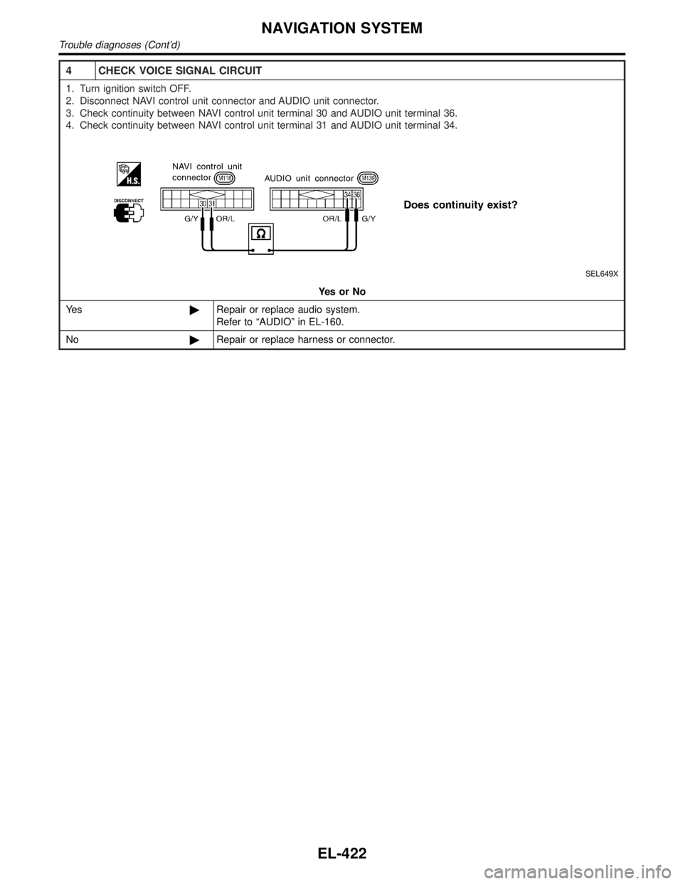
4 CHECK VOICE SIGNAL CIRCUIT
1. Turn ignition switch OFF.
2. Disconnect NAVI control unit connector and AUDIO unit connector.
3. Check continuity between NAVI control unit terminal 30 and AUDIO unit terminal 36.
4. Check continuity between NAVI control unit terminal 31 and AUDIO unit terminal 34.
SEL649X
YesorNo
Ye s©Repair or replace audio system.
Refer to ªAUDIOº in EL-160.
No©Repair or replace harness or connector.
NAVIGATION SYSTEM
Trouble diagnoses (Cont'd)
EL-422
Page 1613 of 2395
Possible cause:
Ð: Vehicle running ---: IndicationDrive condition Service procedure
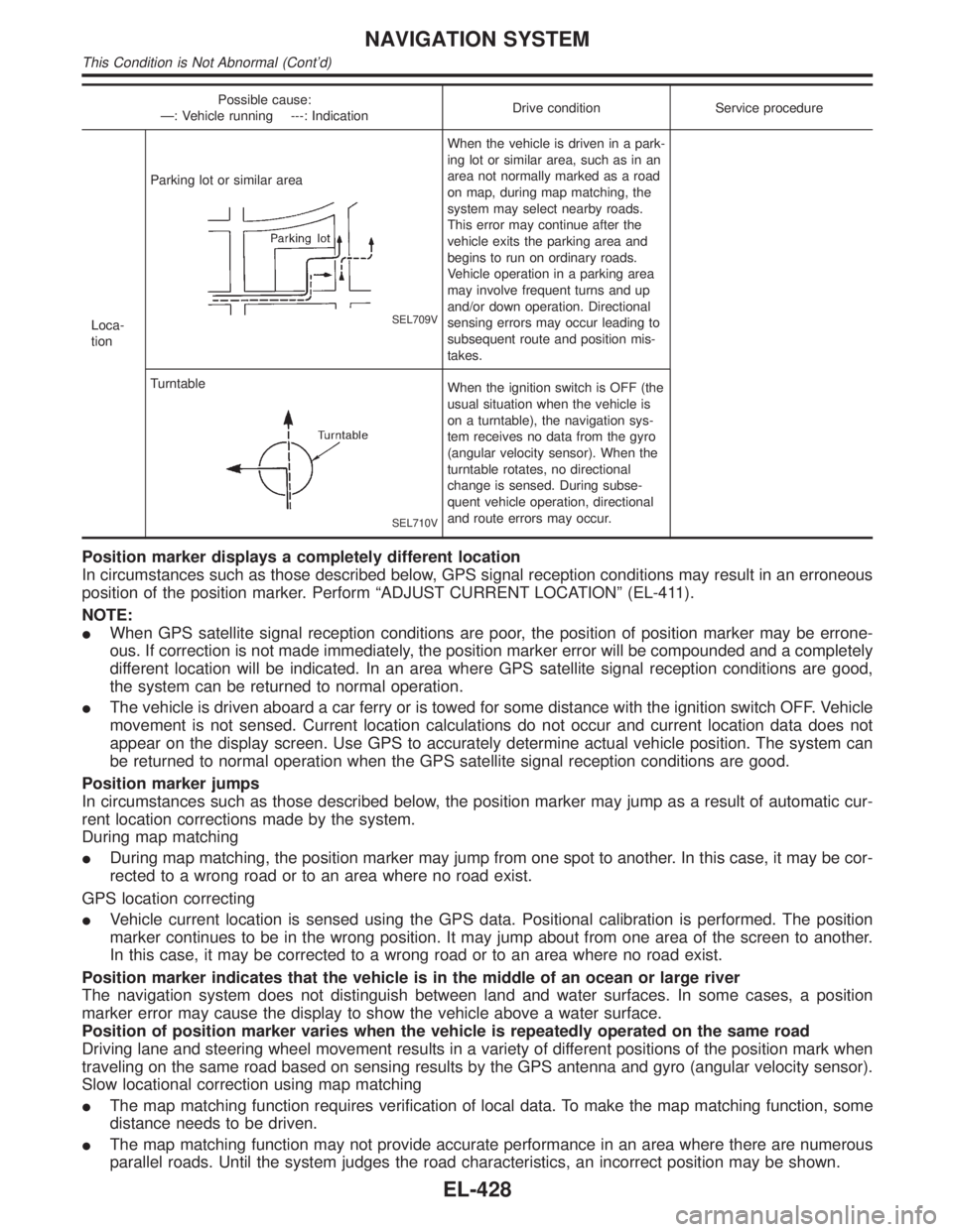
Loca-
tionParking lot or similar area
SEL709V
When the vehicle is driven in a park-
ing lot or similar area, such as in an
area not normally marked as a road
on map, during map matching, the
system may select nearby roads.
This error may continue after the
vehicle exits the parking area and
begins to run on ordinary roads.
Vehicle operation in a parking area
may involve frequent turns and up
and/or down operation. Directional
sensing errors may occur leading to
subsequent route and position mis-
takes.
Turntable
SEL710V
When the ignition switch is OFF (the
usual situation when the vehicle is
on a turntable), the navigation sys-
tem receives no data from the gyro
(angular velocity sensor). When the
turntable rotates, no directional
change is sensed. During subse-
quent vehicle operation, directional
and route errors may occur.
Position marker displays a completely different location
In circumstances such as those described below, GPS signal reception conditions may result in an erroneous
position of the position marker. Perform ªADJUST CURRENT LOCATIONº (EL-411).
NOTE:
IWhen GPS satellite signal reception conditions are poor, the position of position marker may be errone-
ous. If correction is not made immediately, the position marker error will be compounded and a completely
different location will be indicated. In an area where GPS satellite signal reception conditions are good,
the system can be returned to normal operation.
IThe vehicle is driven aboard a car ferry or is towed for some distance with the ignition switch OFF. Vehicle
movement is not sensed. Current location calculations do not occur and current location data does not
appear on the display screen. Use GPS to accurately determine actual vehicle position. The system can
be returned to normal operation when the GPS satellite signal reception conditions are good.
Position marker jumps
In circumstances such as those described below, the position marker may jump as a result of automatic cur-
rent location corrections made by the system.
During map matching
IDuring map matching, the position marker may jump from one spot to another. In this case, it may be cor-
rected to a wrong road or to an area where no road exist.
GPS location correcting
IVehicle current location is sensed using the GPS data. Positional calibration is performed. The position
marker continues to be in the wrong position. It may jump about from one area of the screen to another.
In this case, it may be corrected to a wrong road or to an area where no road exist.
Position marker indicates that the vehicle is in the middle of an ocean or large river
The navigation system does not distinguish between land and water surfaces. In some cases, a position
marker error may cause the display to show the vehicle above a water surface.
Position of position marker varies when the vehicle is repeatedly operated on the same road
Driving lane and steering wheel movement results in a variety of different positions of the position mark when
traveling on the same road based on sensing results by the GPS antenna and gyro (angular velocity sensor).
Slow locational correction using map matching
IThe map matching function requires verification of local data. To make the map matching function, some
distance needs to be driven.
IThe map matching function may not provide accurate performance in an area where there are numerous
parallel roads. Until the system judges the road characteristics, an incorrect position may be shown.
NAVIGATION SYSTEM
This Condition is Not Abnormal (Cont'd)
EL-428
Page 1614 of 2395
GPS signal reception conditions are good. However, the position mark does not return to its proper
position.
Ihe system senses the vehicle location with an error of approximately 100 m (328 ft). Due to the limitation
of precision, the position marker may be inaccurate even if the GPS signal reception condition is good.
IThe navigation system uses GPS data to determine vehicle location. GPS data is compared with other
locational sensing data during the map matching process. The system decides which data is more pre-
cise and uses that data.
IWhen the vehicle is stationary, GPS data cannot be used to make system corrections.
Area designations on the map display and the BIRDVIEWTdisplay differ.
To prevent the display from becoming congested, alphanumeric information is abridged.
[No problem]
Correct position of your vehicle is not displayed.
Vehicle position changed after ignition key was turned to the OFF position (Vehicle is transported on car ferry,
car train, or by some other means).
[Operate vehicle for short time under GPS receiving conditions.]
The display does not change to night-time mode even though the light switch has been turned ON.
Lights have been turned on. In ªDISPLAY CHANGEº mode, night-time mode on display has been switched to
day-time mode and still is.
[Turn lights on again. Set the display to night-time mode. Refer to EL-412.]
Map does not scroll even though the position of your vehicle is changed.
Present area does not appear on the display.
[Press the ªMAPº switch.]
Vehicle position marker does not appear.
Present area does not appear on the display.
[Press the ªMAPº switch.]
The map surface precision display (GPS satellite marker) still remains gray.
Vehicle is parked inside a building or in the shadow of a large building. This intercepts the GPS signal.
[Move the vehicle to a more open position.]
GPS signal is not received because objects are placed on the rear parcel shelf.
[Remove objects from the rear parcel shelf.]
GPS satellite position is bad.
[Wait until GPS satellite position improves.]
Vehicle position precision is bad.
The map surface precision display (GPS satellite marker) still remains gray.
[Refer to ªThe map surface precision display (GPS satellite marker) still remains grayº item (Symptoms)]
Vehicle speed and elapsed distance is calculated from the vehicle speed pulse. This pulse is dependent upon
tire size. If tire chains are used on the vehicle, accuracy will be affected (pulse rate will be too fast or too slow).
The same is true if the system installed to your vehicle is removed and installed on another vehicle.
[Drive the vehicle at a speed higher than 30 km/h (19 MPH) for approximately 30 minutes. Automatic read-
justment should occur. If it does not (remains too fast or too slow), distance calibration is required. Or, drive
the vehicle for a short distance. Perform ªSPEED CALIBRATIONº (EL-409). After removing the tire chains,
sensing accuracy may recover by itself.]
Bad map data or system defect (same error consistently occurs in the same area)
ROUTE SEARCH/ROUTE GUIDENBEL0235S03IIf the present location or the destination location is displayed in the avoid area, it is not possible to search
routes.
IIf the avoid area is set to wide range area, it may not be possible to find appropriate routes or search for
alternate routes.
IThe automatic re-route calculates a return to the original route. Because of this, it may not be possible to
search appropriate new routes. If you deviate from the original route and wish to select an appropriate new
route, touch ªRoute Calculationº.
IThe automatic re-route function may sometimes require considerable time.
IDisplayed route number and directional information at a highway junction may differ from the information
posted on the actual road signs.
IDisplayed street name information at a highway exit may differ from the information posted on the actual
road signs.
IStreet name information displayed on the enlarged intersection map may differ from the information posted
on the actual road signs.
GI
MA
EM
LC
EC
FE
AT
TF
PD
AX
SU
BR
ST
RS
BT
HA
SC
IDX
NAVIGATION SYSTEM
This Condition is Not Abnormal (Cont'd)
EL-429
Page 1641 of 2395

NBEL0144
HeadlampNBEL0144S03
Item Wattage W
High/Low (Semi-sealed beam)55/35 (HB3/D2R)
Exterior LampNBEL0144S01
Item Wattage W
Front fog lamp55
Front turn signal lamp21
Parking lamp5
Rear combination lampTurn signal lamp 27
Stop/Tail lamp 21/5
Back-up lamp18
License plate lamp3.8
High-mounted stop lamp5
Interior LampNBEL0144S02
Item Wattage W
Interior lamp10
Spot lamp8
Luggage room lamp10
BULB SPECIFICATIONS
Headlamp
EL-456
Page 1643 of 2395
Code Section Wiring Diagram Name
NAVI EL Navigation System
NONDTC AT Non-detectable Items
O2H1B1 EC Heated Oxygen Sensor 1 Heater
(Front) (Bank 1)
O2H1B2 EC Heated Oxygen Sensor 1 Heater
(Front) (Bank 2)
O2H2B1 EC Heated Oxygen Sensor 2 Heater
(Rear) (Bank 1)
O2H2B2 EC Heated Oxygen Sensor 2 Heater
(Rear) (Bank 2)
O2S1B1 EC Heated Oxygen Sensor 1 (Front)
(Bank 1)
O2S1B2 EC Heated Oxygen Sensor 1 (Front)
(Bank 2)
O2S2B1 EC Heated Oxygen Sensor 2 (Rear)
(Bank 1)
O2S2B2 EC Heated Oxygen Sensor 2 (Rear)
(Bank 2)
OVRCSV AT Overrun Clutch Solenoid Valve
P/ANT EL Power Antenna
PGC/V EC EVAP Canister Purge Volume
Control Solenoid Valve
PHASE EC Camshaft Position Sensor
(PHASE)
PNP/SW EC Park/Neutral Position Switch
PNP/SW AT Park/Neutral Position Switch
POS EC Crankshaft Position Sensor
(CKPS) (POS)
POWER EL Power Supply Routing
PRE/SE EC EVAP Control System Pressure
Sensor
PST/SW EC Power Steering Oil Pressure
Switch
REF EC Crankshaft Position Sensor
(CKPS) (REF)
REMOTE EL Audio (Remote Control Switch)
RP/SEN EC Refrigerant Pressure
S/SIG EC Start Signal
S/VCSW EC Swirl Control Valve Control
Vacuum Check Switch
SEAT EL Power Seat
SHIFT AT A/T Shift Lock System
SROOF EL Sunroof
SRS RS Supplemental Restraint SystemCode Section Wiring Diagram Name
SSV/A AT Shift Solenoid Valve A
SSV/B AT Shift Solenoid Valve B
START SC Starting System
STOP/L EL Stop lamp
SWL/V EC Swirl Control Valve Control Sole-
noid Valve
TAIL/L EL Parking, License and Tail Lamps
TCCSIG AT A/T TCC Signal (Lock up)
TCV AT Torque Converter Clutch Solenoid
Valve
T/F TF Transfer
TFTS EC Tank Fuel Temperature Sensor
THEFT EL Theft Warning System
TLID EL Glass Hatch Opener
TP/SW EC Throttle Position Switch
TPS AT Throttle Position Sensor
TPS EC Throttle Position Sensor
TRNSMT EL Integrated HOMELINKYTrans-
mitter
TRSA/T AT Turbine Revolution Sensor
TURN EL Turn Signal and Hazard Warning
Lamps
VIAS/V EC Variable Induction Air Control Sys-
tem
VSS EC Vehicle Speed Sensor
VSSA/T AT Vehicle Speed Sensor A/T (Revo-
lution Sensor)
VSSMTR AT Vehicle Speed Sensor MTR
WARN EL Warning Lamps
WINDOW EL Power Window
WIP/R EL Rear Wiper and Washer
WIPER EL Front Wiper and Washer
WIRING DIAGRAM CODES (CELL CODES)
EL-458
Page 1668 of 2395

SEM415G
17. Disconnect injector harness connectors.
18. Remove fuel tube assembly in reverse order of installation.
Refer to EM-12, ªFuel Tubeº.
SEM416G
19. Remove ignition coils.
20. Remove RH and LH rocker covers from cylinder head.
SEM417G
21. Set No. 1 piston at TDC on the compression stroke by rotat-
ing crankshaft.
IAlign pointer with TDC mark on crankshaft pulley.
SEM418G
ICheck that intake and exhaust cam nose on No. 1 cylinder are
installed as shown left.
If not, turn the crankshaft one revolution (360É) and align as
above.
SEM485G
22. Remove starter motor, and set ring gear stopper using the
mounting bolt hole.
IBe careful not to damage the signal plate teeth.
GI
MA
LC
EC
FE
AT
TF
PD
AX
SU
BR
ST
RS
BT
HA
SC
EL
IDX
TIMING CHAIN
Removal (Cont'd)
EM-25
Page 1676 of 2395

SEM439G
SEM440G
17. Install RH and LH rocker covers.
Rocker cover tightening procedure:
ITighten in numerical order as shown in the figure.
a. Tighten bolts 1 to 10 in that order to 6.9 to 8.8 N´m (0.7 to 0.9
kg-m, 61 to 78 in-lb).
b. Then tighten bolts 1 to 10 as indicated in figure to 6.9 to 8.8
N´m (0.7 to 0.9 kg-m, 61 to 78 in-lb).
18. Hang engine using the right and left side engine slingers with
a suitable hoist.
19. Set a suitable transmission jack under the suspension mem-
ber.
20. Remove right and left side engine mounting nuts.
21. Remove right and left side suspension member bolts.
22. Install aluminum oil pan. Refer to EM-18, ªInstallationº.
23. Set ring gear stopper using the mounting bolt hole.
IBe careful not to damage the signal plate teeth.
SEM417G
24. Install crankshaft pulley to crankshaft.
IAlign pointer with TDC mark on crankshaft pulley.
SEM531G
25. Install crankshaft pulley bolt.
ILubricate thread and seat surface of the bolt with new
engine oil.
a. Tighten to 39 to 49 N´m (4.0 to 5.0 kg-m, 29 to 36 ft-lb).
b. Put a paint mark on the crankshaft pulley.
SEM963E
c. Again tighten by turning 60É to 66É, about the angle from one
hexagon bolt head corner to another.
26. Install camshaft position sensor (PHASE), crankshaft position
sensors (REF)/(POS) and CVTC sensors.
27. Reinstall removed parts in the reverse order of removal.
IWhen installing fuel tube and intake manifold collectors, refer
to EM-12, ªTIGHTENING PROCEDURESº.
IAfter starting engine, keep idling for three minutes. Then
rev engine up to 3,000 rpm under no load to purge air from
the high-pressure chamber of the chain tensioners. The
engine may produce a rattling noise. This indicates that
GI
MA
LC
EC
FE
AT
TF
PD
AX
SU
BR
ST
RS
BT
HA
SC
EL
IDX
TIMING CHAIN
Installation (Cont'd)
EM-33
Page 1713 of 2395
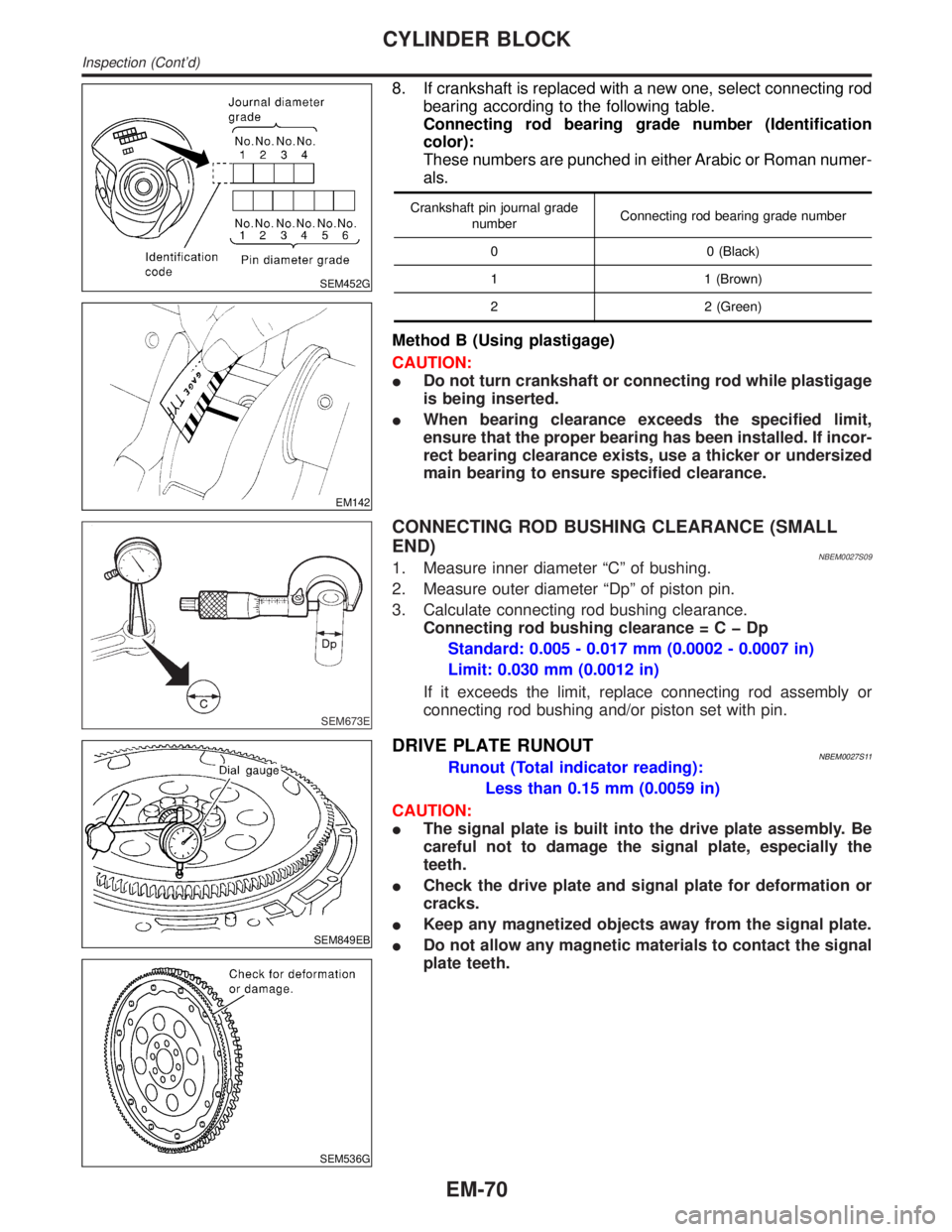
SEM452G
EM142
8. If crankshaft is replaced with a new one, select connecting rod
bearing according to the following table.
Connecting rod bearing grade number (Identification
color):
These numbers are punched in either Arabic or Roman numer-
als.
Crankshaft pin journal grade
numberConnecting rod bearing grade number
0 0 (Black)
1 1 (Brown)
2 2 (Green)
Method B (Using plastigage)
CAUTION:
IDo not turn crankshaft or connecting rod while plastigage
is being inserted.
IWhen bearing clearance exceeds the specified limit,
ensure that the proper bearing has been installed. If incor-
rect bearing clearance exists, use a thicker or undersized
main bearing to ensure specified clearance.
SEM673E
CONNECTING ROD BUSHING CLEARANCE (SMALL
END)
NBEM0027S091. Measure inner diameter ªCº of bushing.
2. Measure outer diameter ªDpº of piston pin.
3. Calculate connecting rod bushing clearance.
Connecting rod bushing clearance=CþDp
Standard: 0.005 - 0.017 mm (0.0002 - 0.0007 in)
Limit: 0.030 mm (0.0012 in)
If it exceeds the limit, replace connecting rod assembly or
connecting rod bushing and/or piston set with pin.
SEM849EB
SEM536G
DRIVE PLATE RUNOUTNBEM0027S11Runout (Total indicator reading):
Less than 0.15 mm (0.0059 in)
CAUTION:
IThe signal plate is built into the drive plate assembly. Be
careful not to damage the signal plate, especially the
teeth.
ICheck the drive plate and signal plate for deformation or
cracks.
IKeep any magnetized objects away from the signal plate.
IDo not allow any magnetic materials to contact the signal
plate teeth.
CYLINDER BLOCK
Inspection (Cont'd)
EM-70