2001 DODGE RAM heater
[x] Cancel search: heaterPage 594 of 2889
behind the cutout causes the ªWAIT TO STARTº text
to appear in red through the translucent outer layer
of the overlay when the indicator is illuminated from
behind by a Light Emitting Diode (LED) that is sol-
dered onto the instrument cluster electronic circuit
board. The wait-to-start indicator is serviced as a
unit with the instrument cluster.
OPERATION
The wait-to-start indicator gives an indication to
the vehicle operator when the diesel engine intake
air heater is energized in its preheat operating mode.
This indicator is controlled by a hard wired input to
the instrument cluster from the Engine Control Mod-
ule (ECM). The wait-to-start indicator Light Emitting
Diode (LED) receives battery current on the instru-
ment cluster electronic circuit board through the
fused ignition switch output (st-run) circuit whenever
the ignition switch is in the On or Start positions;
therefore, the lamp will always be off when the igni-
tion switch is in any position except On or Start. The
indicator LED only illuminates when it is switched to
ground by the input from the ECM. The ECM will
turn on the wait-to-start indicator by pulling the
wait-to-start indicator driver circuit to ground each
time the ignition switch is turned to the On or Start
positions. The indicator then remains illuminated
until the ECM detects that the air within the intake
manifold is the proper temperature to ensure reliable
and efficient engine starting, until the ECM detects
that the engine is running, or until the ignition
switch is turned to the Off position, whichever occurs
first.
The ECM continually monitors the intake manifold
air temperature sensor, the Manifold Absolute Pres-
sure (MAP) sensor, and many other vehicle condi-
tions to determine when the wait-to-start indicator
should be illuminated. For proper diagnosis of the
wait-to-start indicator, the ECM, or the inputs the
ECM uses to control the wait-to-start indicator oper-
ation, a DRBIIItscan tool is required. Refer to the
appropriate diagnostic information.
WASHER FLUID INDICATOR
DESCRIPTION
A washer fluid indicator is standard equipment on
all instrument clusters. The washer fluid indicator is
located near the lower edge of the instrument cluster
overlay, to the right of center. The washer fluid indi-
cator consists of a stenciled cutout of the words
ªLOW WASHERº in the opaque layer of the instru-
ment cluster overlay. The dark outer layer of the
overlay prevents the indicator from being clearly vis-
ible when it is not illuminated. An amber lens behindthe cutout in the opaque layer of the overlay causes
the ªLOW WASHERº text to appear in amber
through the translucent outer layer of the overlay
when it is illuminated from behind by a Light Emit-
ting Diode (LED) soldered onto the instrument clus-
ter electronic circuit board. The washer fluid
indicator is serviced as a unit with the instrument
cluster.
OPERATION
The washer fluid indicator gives an indication to
the vehicle operator when the fluid level in the
washer fluid reservoir is low. This indicator is con-
trolled by a transistor on the instrument cluster elec-
tronic circuit board based upon cluster programming
and a hard wired washer fluid level switch input to
the cluster. The washer fluid indicator Light Emit-
ting Diode (LED) receives battery current on the
instrument cluster electronic circuit board through
the fused ignition switch output (st-run) circuit
whenever the ignition switch is in the On or Start
positions; therefore, the indicator will always be off
when the ignition switch is in any position except On
or Start. The LED only illuminates when it is pro-
vided a path to ground by the instrument cluster
transistor. The instrument cluster will turn on the
washer fluid indicator for the following reasons:
²Bulb Test- Each time the ignition switch is
turned to the On position the indicator is illuminated
for about two seconds as a bulb test.
²Washer Fluid Level Switch Input- Immedi-
ately after the bulb test, if the cluster senses ground
on the washer fluid switch sense circuit for more
than about thirty seconds, it turns on the washer
fluid indicator. Any time after the bulb test, the clus-
ter must sense ground on the washer fluid switch
sense circuit for more than about sixty seconds before
it turns on the indicator. Once illuminated, the indi-
cator will remain illuminated until the ignition
switch is cycled and the cluster senses an open cir-
cuit on the low washer fluid sense input. This strat-
egy is intended to reduce the effect that fluid
sloshing within the washer reservoir can have on
reliable indicator operation.
²Actuator Test- Each time the cluster is put
through the actuator test, the indicator will be
turned on during the bulb check portion of the test to
confirm the functionality of the LED and the cluster
control circuitry.
The washer fluid level switch is connected in series
between ground and the washer fluid switch sense
input to the instrument cluster. For more informa-
tion on the washer fluid level switch,(Refer to 8 -
ELECTRICAL/WIPERS/WASHERS/WASHER FLUID
LEVEL SWITCH - OPERATION). For further diag-
nosis of the washer fluid indicator or the instrument
BR/BEINSTRUMENT CLUSTER 8J - 35
WAIT-TO-START INDICATOR (Continued)
Page 630 of 2889
LAMPS/LIGHTING - INTERIOR
TABLE OF CONTENTS
page page
LAMPS/LIGHTING - INTERIOR
SPECIFICATIONS........................33
DOME LAMP
REMOVAL..............................33
INSTALLATION...........................33
DOOR AJAR SWITCH
DESCRIPTION...........................34
DIAGNOSIS AND TESTING.................34
DOOR AJAR SWITCH....................34
REMOVAL..............................35
INSTALLATION...........................35GLOVE BOX LAMP AND SWITCH
REMOVAL..............................35
INSTALLATION...........................35
READING LAMP
DESCRIPTION...........................36
OPERATION.............................36
REMOVAL..............................36
INSTALLATION...........................36
VANITY LAMP
REMOVAL..............................37
INSTALLATION...........................37
LAMPS/LIGHTING - INTERIOR
SPECIFICATIONS
INTERIOR LAMPS
LAMP BULB
A/C HEATER CONTROL 158
ASH RECEIVER 161
CIGAR LIGHTER 161
HEADLAMP SWITCH 158
HEATER CONTROL 158
INSTRUMENT CLUSTER PC194
RADIO ASC
AIRBAG HIGH LINE PC194
AIRBAG LOW LINE PC74
ANTI-LOCK BRAKE PC74
BATTERY VOLTAGE PC194
BRAKE WARNING PC194
CHECK ENGINE PC74
ENGINE OIL PRESSURE PC74
FOUR WHEEL DRIVE PC194
HIGH BEAM PC194
LOW FUEL PC194
LOW WASHER FLUID PC74
MAINTENANCE
REQUIREDPC74
MESSAGE CENTER PC194
SEAT BELT PC74
LAMP BULB
TURN SIGNAL PC194
UPSHIFT PC74
DOME 1004
GLOVE COMPARTMENT 1891
VANITY MIRROR LAMP P/N 6501966
DOME LAMP
REMOVAL
(1) Using a small flat blade, pry the left side (driv-
er's side) of the dome lamp lens downward from
dome lamp.
(2) Allow the lens to hang down (Fig. 1) , this will
disengage the right side of the lamp (passenger's
side) from the headliner.
(3) Pull the right side of the lamp down and slide
the lamp to the right (Fig. 2) .
(4) Separate the lamp from the headliner.
(5) Disengage dome lamp wire connector from body
wire harness.
(6) Separate dome lamp from vehicle.
INSTALLATION
(1) Position dome lamp at headliner.
(2) Connect dome lamp wire connector to body
wire harness.
(3) Position the left side of the lamp in the head-
liner opening and slide lamp to the left.
(4) Push the right side of the lamp in the head-
liner opening and push the lamp lens up into the
lamp to secure.
BR/BELAMPS/LIGHTING - INTERIOR 8L - 33
Page 659 of 2889

POWER MIRRORS
TABLE OF CONTENTS
page page
POWER MIRRORS
DESCRIPTION...........................10
OPERATION.............................10
AUTOMATIC DAY / NIGHT MIRROR
DESCRIPTION...........................10
OPERATION.............................11
DIAGNOSIS AND TESTING.................11
AUTOMATIC DAY/NIGHT MIRROR..........11
REMOVAL..............................12
INSTALLATION...........................12
POWER MIRROR SWITCH
DESCRIPTION...........................12OPERATION.............................12
REMOVAL..............................12
INSTALLATION...........................13
SIDEVIEW MIRROR
DESCRIPTION...........................13
OPERATION.............................13
DIAGNOSIS AND TESTING.................13
SIDEVIEW MIRROR.....................13
REMOVAL..............................14
POWER MIRRORS
DESCRIPTION
AUTOMATIC DAY / NIGHT MIRROR
The automatic day/night mirror system is able to
automatically change the reflectance of the inside
rear view mirror in order to reduce the glare of head-
lamps approaching the vehicle from the rear. The
automatic day/night rear view mirror receives bat-
tery current through a fuse in the junction block only
when the ignition switch is in the On position.
OUTSIDE REAR VIEW MIRROR
The heated mirror option includes an electric heat-
ing grid behind the mirror glass in each outside mir-
ror, which can clear the mirror glass of ice, snow, or
fog. The heating grid receives fused battery current
through the heated mirror relay in the heater and air
conditioner control only when the ignition switch is
in the On position, and the heated mirror system is
turned on. (Refer to 8 - ELECTRICAL/HEATED
MIRRORS - DESCRIPTION) for more information.
Refer to the owner's manual in the vehicle glove
box for more information on the features, use and
operation of the power mirror system.
OPERATION
AUTOMATIC DAY / NIGHT MIRROR
A switch located on the bottom of the automatic
day/night mirror housing allows the vehicle operator
to select whether the automatic dimming feature is
operational. When the automatic day/night mirror isturned on, the mirror switch is lighted by an integral
Light-Emitting Diode (LED). The mirror will auto-
matically disable its self-dimming feature whenever
the vehicle is being driven in reverse.
Refer to the owner's manual in the vehicle glove
box for more information on the features, use and
operation of the automatic day/night mirror system.
OUTSIDE REAR VIEW MIRROR
The heated mirror option includes an electric heat-
ing grid behind the mirror glass in each outside mir-
ror, which can clear the mirror glass of ice, snow, or
fog. The heating grid receives fused battery current
through the heated mirror relay in the heater and air
conditioner control only when the ignition switch is
in the On position, and the heated mirror system is
turned on. (Refer to 8 - ELECTRICAL/HEATED
MIRRORS - OPERATION) for more information.
Refer to the owner's manual in the vehicle glove
box for more information on the features, use and
operation of the power mirror system.
AUTOMATIC DAY / NIGHT
MIRROR
DESCRIPTION
The automatic day/night mirror uses a thin layer
of electrochromic material between two pieces of con-
ductive glass to make up the face of the mirror.
When the mirror switch is in the On position, two
photocell sensors are used by the mirror circuitry to
monitor external light levels and adjust the reflec-
tance of the mirror.
8N - 10 POWER MIRRORSBR/BE
Page 662 of 2889
(3) Remove the nut that secures the power mirror
switch to the driver side front door trim panel.
(4) Remove the trim panel from the inside of the
driver side front door. (Refer to 23 - BODY/DOOR -
FRONT/TRIM PANEL - REMOVAL) for the proce-
dures.
(5) Pull the trim panel away from the inner door
far enough to access the power mirror switch wire
harness connector.
(6) Unplug the power mirror switch wire harness
connector.
(7) Remove the power mirror switch from the back
of the door trim panel.
INSTALLATION
(1) Insert the power mirror switch to the back of
the door trim panel.
(2) Connect the power mirror switch to the har-
ness connector.
(3) Install the trim panel to the inside of the
driver side door. (Refer to 23 - BODY/DOOR -
FRONT/TRIM PANEL - INSTALLATION).
(4) Install the nut that secures the power mirror
switch to the driver side front door.
(5) Push the control knob on to the power mirror
switch.
(6) Connect the battery negative cable.
SIDEVIEW MIRROR
DESCRIPTION
Each power mirror head contains two electric
motors, two drive mechanisms, and the mirror glass.
One motor and drive controls mirror up-and-down
movement, and the other controls right-and-left
movement.
OPERATION
The power mirrors in vehicles equipped with the
available heated mirror system option also include an
electric heating grid located behind the mirror glass.
This heating grid is energized by the heated mirror
relay in the heater and air conditioner control only
when the ignition switch is in the On position, and
the heated mirror system is turned on. (Refer to 8 -
ELECTRICAL/HEATED MIRRORS - DESCRIP-
TION) for more information.
The power mirror assembly cannot be repaired. If
any component of the power mirror unit is faulty or
damaged, the entire assembly must be replaced.
DIAGNOSIS AND TESTING - SIDEVIEW
MIRROR
For circuit descriptions and diagrams, refer to the
appropriate wiring information. The wiring informa-
tion includes wiring diagrams, proper wire and con-
nector repair procedures, details of wire harness
routing and retention, connector pin-out information
and location views for the various wire harness con-
nectors, splices and grounds.
(1) Check the fuses in the Power Distribution Cen-
ter (PDC) and the junction block. If OK, go to Step 2.
If not OK, repair the shorted circuit or component as
required and replace the faulty fuse(s).
(2) Check for battery voltage at the fuse in the
junction block. If OK, go to Step 3. If not OK, repair
the open circuit to the PDC as required.
(3) Disconnect and isolate the battery negative
cable. Remove the driver side door trim panel and
unplug the wire harness connector from the power
mirror switch. Connect the battery negative cable.
Check for battery voltage at the fused B(+) circuit
cavity in the door wire harness half of the power mir-
ror switch wire harness connector. If OK, go to Step
4. If not OK, repair the open circuit to the junction
block as required.
BR/BEPOWER MIRRORS 8N - 13
POWER MIRROR SWITCH (Continued)
Page 680 of 2889
WARNING: IF YOU EXPERIENCE SKIN IRRITATION
DURING CLEANUP, RUN COOL WATER OVER THE
AFFECTED AREA. ALSO, IF YOU EXPERIENCE
IRRITATION OF THE NOSE OR THROAT, EXIT THE
VEHICLE FOR FRESH AIR UNTIL THE IRRITATION
CEASES. IF IRRITATION CONTINUES, SEE A PHYSI-
CIAN.
Begin the cleanup by removing both airbags from
the vehicle. Refer to the appropriate service removal
procedures. Place the deployed airbags in your vehic-
ular scrap pile.
Next, use a vacuum cleaner to remove any residual
powder from the vehicle interior. Clean from outside
the vehicle and work your way inside, so that you
avoid kneeling or sitting on a non-cleaned area. Be
certain to vacuum the heater and air conditioning
outlets as well (Fig. 3). Run the heater and air con-
ditioner blower on the lowest speed setting and vac-
uum any powder expelled from the outlets. You may
need to vacuum the interior of the vehicle a second
time to recover all of the powder.
STANDARD PROCEDURE - VERIFICATION TEST
The following procedure should be performed using
a DRBIIItscan tool to verify proper airbag system
operation following the service or replacement of any
airbag system component.
WARNING: ON VEHICLES EQUIPPED WITH AIR-
BAGS, DISABLE THE AIRBAG SYSTEM BEFORE
ATTEMPTING ANY STEERING WHEEL, STEERING
COLUMN, OR INSTRUMENT PANEL COMPONENT
DIAGNOSIS OR SERVICE. DISCONNECT AND ISO-
LATE THE BATTERY NEGATIVE (GROUND) CABLE,
THEN WAIT TWO MINUTES FOR THE AIRBAG SYS-
TEM CAPACITOR TO DISCHARGE BEFORE PER-
FORMING FURTHER DIAGNOSIS OR SERVICE. THIS
IS THE ONLY SURE WAY TO DISABLE THE AIRBAGSYSTEM. FAILURE TO TAKE THE PROPER PRECAU-
TIONS COULD RESULT IN ACCIDENTAL AIRBAG
DEPLOYMENT AND POSSIBLE PERSONAL INJURY.
(1) During the following test, the battery negative
cable remains disconnected and isolated, as it was
during the airbag component removal and installa-
tion procedures.
(2) Be certain that the DRBIIItscan tool contains
the latest version of the proper DRBIIItsoftware.
Connect the DRBIIItto the 16-way Data Link Con-
nector (DLC). The DLC is located on the driver side
lower edge of the instrument panel, outboard of the
steering column (Fig. 4).
(3) Turn the ignition switch to the On position and
exit the vehicle with the DRBIIIt.
(4) Check to be certain that nobody is in the vehi-
cle, then reconnect the battery negative cable.
(5) Using the DRBIIIt, read and record the active
(current) Diagnostic Trouble Code (DTC) data.
(6) Next, use the DRBIIItto read and record any
stored (historical) DTC data.
(7) If any DTC is found in Step 5 or Step 6, refer
to the appropriate diagnostic information.
(8) Use the DRBIIItto erase the stored DTC data.
If any problems remain, the stored DTC data will not
erase. Refer to the appropriate diagnostic informa-
tion to diagnose any stored DTC that will not erase.
If the stored DTC information is successfully erased,
go to Step 9.
Fig. 3 Vacuum Heater and A/C Outlets - Typical
Fig. 4 16-Way Data Link Connector - Typical
1 - 16±WAY DATA LINK CONNECTOR
2 - BOTTOM OF INSTRUMENT PANEL
BR/BERESTRAINTS 8O - 5
RESTRAINTS (Continued)
Page 742 of 2889
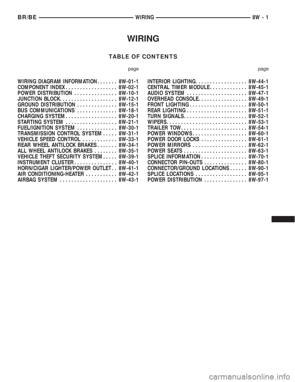
WIRING
TABLE OF CONTENTS
page page
WIRING DIAGRAM INFORMATION....... 8W-01-1
COMPONENT INDEX.................. 8W-02-1
POWER DISTRIBUTION............... 8W-10-1
JUNCTION BLOCK.................... 8W-12-1
GROUND DISTRIBUTION.............. 8W-15-1
BUS COMMUNICATIONS.............. 8W-18-1
CHARGING SYSTEM.................. 8W-20-1
STARTING SYSTEM.................. 8W-21-1
FUEL/IGNITION SYSTEM.............. 8W-30-1
TRANSMISSION CONTROL SYSTEM..... 8W-31-1
VEHICLE SPEED CONTROL............ 8W-33-1
REAR WHEEL ANTILOCK BRAKES....... 8W-34-1
ALL WHEEL ANTILOCK BRAKES........ 8W-35-1
VEHICLE THEFT SECURITY SYSTEM..... 8W-39-1
INSTRUMENT CLUSTER............... 8W-40-1
HORN/CIGAR LIGHTER/POWER OUTLET . . 8W-41-1
AIR CONDITIONING-HEATER........... 8W-42-1
AIRBAG SYSTEM.................... 8W-43-1INTERIOR LIGHTING.................. 8W-44-1
CENTRAL TIMER MODULE............. 8W-45-1
AUDIO SYSTEM..................... 8W-47-1
OVERHEAD CONSOLE................. 8W-49-1
FRONT LIGHTING.................... 8W-50-1
REAR LIGHTING..................... 8W-51-1
TURN SIGNALS...................... 8W-52-1
WIPERS............................ 8W-53-1
TRAILER TOW....................... 8W-54-1
POWER WINDOWS................... 8W-60-1
POWER DOOR LOCKS................ 8W-61-1
POWER MIRRORS................... 8W-62-1
POWER SEATS...................... 8W-63-1
SPLICE INFORMATION................ 8W-70-1
CONNECTOR PIN-OUTS............... 8W-80-1
CONNECTOR/GROUND LOCATIONS...... 8W-90-1
SPLICE LOCATIONS.................. 8W-95-1
POWER DISTRIBUTION............... 8W-97-1 BR/BEWIRING 8W - 1
Page 756 of 2889

8W-02 COMPONENT INDEX
Component Page
4WD Switch.......................... 8W-31
A/C Compressor Clutch Relay............ 8W-42
A/C Compressor Clutch................. 8W-42
A/C-Heater Control.................... 8W-42
A/C Heater Temperature Select........... 8W-42
A/C High Pressure Switch............... 8W-42
A/C Low Pressure Switch................ 8W-42
Accelerator Pedal Position Sensor......... 8W-30
Aftermarket Center High Mounted
Stop Lamp......................... 8W-51
Aftermarket Trailer Tow Connector........ 8W-54
Airbag Control Module.................. 8W-43
Ambient Temperature Sensor............ 8W-49
Ash Receiver Lamp.................... 8W-44
Automatic Day/Night Mirror............. 8W-49
Automatic Shut Down Relay............. 8W-30
Auxiliary Battery...................... 8W-20
Back-Up Lamp Switch.................. 8W-51
Back-Up Lamps....................... 8W-51
Battery Temperature Sensor............. 8W-30
Battery............................. 8W-20
Blend Door Actuator................... 8W-42
Blower Motor Relay.................... 8W-42
Blower Motor Resistor Block............. 8W-42
Blower Motor......................... 8W-42
Brake Lamp Switch.................... 8W-51
Brake Pressure Switch............... 8W-34, 35
Bypass Jumper....................... 8W-21
Camshaft Position Sensor............... 8W-30
Capacitor......................... 8W-10, 30
Cargo Lamps......................... 8W-44
Center High Mounted Stop Lamps........ 8W-51
Center Identification Lamp.............. 8W-50
Central Timer Module.................. 8W-45
Cigar Lighter......................... 8W-41
Circuit Breakers...................... 8W-12
Clockspring.................. 8W-33, 41, 43, 47
Clutch Pedal Position Switch............. 8W-21
Combination Flasher................... 8W-52
Controller Antilock Brake............ 8W-34, 35
Crankshaft Position Sensor.............. 8W-30
Cummins Bus........................ 8W-18
Cup Holder Lamp..................... 8W-44
Cylinder Lock Switches................ 8W-39
Data Link Connector................... 8W-18
Daytime Running Lamp Module.......... 8W-50
Dome Lamp.......................... 8W-44
Door Ajar Switches.................... 8W-45
Door Lock Motors..................... 8W-61
Door Window/Lock Switches.......... 8W-60, 61
Driver Airbag......................... 8W-43
Duty Cycle EVAP/Purge Solenoid......... 8W-30Component Page
Electric Brake Provision................ 8W-54
Engine Control Module.............. 8W-30, 70
Engine Coolant Temperature Sensor....... 8W-30
Engine Oil Pressure Sensor.............. 8W-30
Engine Starter Motor Relay.............. 8W-21
Engine Starter Motor................... 8W-21
Fender Lamp......................... 8W-51
Fog Lamp Indicator.................... 8W-50
Fog Lamp Relay....................... 8W-50
Fog Lamp............................ 8W-50
Fuel Heater Relay..................... 8W-30
Fuel Heater.......................... 8W-30
Fuel Injection Pump................... 8W-30
Fuel Injectors......................... 8W-30
Fuel Transfer Pump.................... 8W-30
Fuses (JB)........................... 8W-12
Fuses (PDC).......................... 8W-10
Fusible Link....................... 8W-20, 30
Generator............................ 8W-20
Glove Box Lamp And Switch............. 8W-44
Grounds............................. 8W-15
Headlamp Beam Select Switch........... 8W-50
Headlamp Switch...................... 8W-50
Headlamp........................... 8W-50
Heated Mirror Relay................... 8W-62
Heated Mirror Switch.................. 8W-62
Heated Seat Cushions.................. 8W-63
Heated Seat Relay..................... 8W-12
Heated Seat Switches.................. 8W-63
High Beam Indicator................... 8W-40
High Note Horn....................... 8W-41
Horn Relay.......................... 8W-41
Horn Switch.......................... 8W-41
Idle Air Control Motor.................. 8W-30
Ignition Coil 4-Pack.................... 8W-30
Ignition Coil 6-Pack.................... 8W-30
Ignition Coil.......................... 8W-30
Ignition Switch....................... 8W-10
Instrument Cluster.................... 8W-40
Intake Air Heater Relays................ 8W-30
Intake Air Heater..................... 8W-30
Intake Air Temperature Sensor........... 8W-30
Intermittent Wiper Switch............... 8W-53
Joint Connectors . . 8W-10, 12, 15, 30, 31, 34, 35, 40,
44, 45, 51, 53, 70
Junction Block........................ 8W-12
Leak Detection Pump.................. 8W-30
License Lamp......................... 8W-51
Low Note Horn....................... 8W-41
Lumbar Motors....................... 8W-63
Manifold Absolute Pressure Sensor........ 8W-30
Manifold Air Pressure Sensor............ 8W-30
BR/BE8W-02 COMPONENT INDEX 8W - 02 - 1
Page 758 of 2889

8W-10 POWER DISTRIBUTION
Component Page
A/C Compressor Clutch Relay.......... 8W-10-27
A/C Compressor Clutch............... 8W-10-27
Aftermarket Center High Mounted
Stop Lamp....................... 8W-10-13
Aftermarket Trailer Tow Connector...... 8W-10-21
Automatic Shut Down Relay......... 8W-10-14, 20
Auxiliary Battery..................... 8W-10-8
Battery............................ 8W-10-8
Blower Motor Relay.................. 8W-10-23
Blower Motor....................... 8W-10-23
Brake Lamp Switch.................. 8W-10-13
Capacitor.......................... 8W-10-16
Center High Mounted Stop Lamp No. 1 . . . 8W-10-13
Center High Mounted Stop Lamp No. 2 . . . 8W-10-13
Central Timer Module C1............. 8W-10-22
Central Timer Module C2............. 8W-10-26
Circuit Breaker 2.................... 8W-10-10
Clockspring........................ 8W-10-26
Combination Flasher................. 8W-10-13
Controller Antilock Brake............. 8W-10-23
Daytime Running Lamp Module........ 8W-10-25
Electric Brake Provision............ 8W-10-13, 21
Engine Control Module............... 8W-10-12
Engine Starter Motor Relay............ 8W-10-23
Engine Starter Motor................. 8W-10-23
Fog Lamp Relay..................... 8W-10-25
Fuel Heater Relay................... 8W-10-20
Fuel Heater........................ 8W-10-20
Fuel Injection Pump.................. 8W-10-12
Fuel Injector No. 1................ 8W-10-15, 16
Fuel Injector No. 2................ 8W-10-15, 16
Fuel Injector No. 3................ 8W-10-15, 16
Fuel Injector No. 4................ 8W-10-15, 16
Fuel Injector No. 5................ 8W-10-15, 16
Fuel Injector No. 6................ 8W-10-15, 16
Fuel Injector No. 7................ 8W-10-15, 16
Fuel Injector No. 8................ 8W-10-15, 16
Fuel Injector No. 9................... 8W-10-16
Fuel Injector No. 10.................. 8W-10-16
Fuel Pump Module................... 8W-10-11
Fuel Pump Relay................. 8W-10-11, 12
Fuse 1 (JB)........................ 8W-10-10
Fuse 1 (PDC)..................... 8W-10-10, 8
Fuse 2 (PDC).................. 8W-10-8, 10, 22
Fuse 3 (PDC).................. 8W-10-8, 11, 12
Fuse 4 (JB)........................ 8W-10-10
Fuse 4 (PDC)..................... 8W-10-13, 8
Fuse 5 (PDC)..................... 8W-10-13, 8
Fuse 6 (PDC).................. 8W-10-14, 20, 8
Fuse 7 (PDC)..................... 8W-10-20, 8
Fuse 8 (PDC)..................... 8W-10-21, 8
Fuse 9 (PDC)..................... 8W-10-23, 8
Fuse 10 (PDC).................... 8W-10-22, 8
Fuse 11 (PDC).................... 8W-10-23, 8
Fuse 12 (JB)....................... 8W-10-10
Fuse 12 (PDC).................... 8W-10-23, 8
Fuse 13 (JB)....................... 8W-10-10Component Page
Fuse 14 (JB)....................... 8W-10-10
Fuse B (PDC)..................... 8W-10-24, 9
Fuse C (PDC)..................... 8W-10-24, 9
Fuse E (PDC)..................... 8W-10-24, 9
Fuse F (PDC)..................... 8W-10-24, 9
Fuse G (PDC)..................... 8W-10-25, 9
Fuse GEN (PDC).................. 8W-10-27, 8
Fuse H (PDC).................... 8W-10-26, 9
Fuse I (PDC)..................... 8W-10-26, 9
Fuse J (PDC)..................... 8W-10-27, 9
Fuse K (PDC)..................... 8W-10-14, 9
Fuse L (PDC)..................... 8W-10-27, 9
G201............................. 8W-10-22
Generator......................... 8W-10-27
Headlamp Beam Select Switch.......... 8W-10-25
Headlamp Switch.................... 8W-10-24
High Note Horn..................... 8W-10-26
Horn Relay...................... 8W-10-26, 9
Ignition Coil 4-Pack.................. 8W-10-16
Ignition Coil 6-Pack.................. 8W-10-16
Ignition Coil........................ 8W-10-15
Ignition Switch................... 8W-10-10, 22
Joint Connector No. 1.............. 8W-10-25, 26
Joint Connector No. 2..... 8W-10-11, 12, 14, 20, 21
Joint Connector No. 5................ 8W-10-22
Joint Connector No. 6........... 8W-10-13, 22, 26
Joint Connector No. 8................ 8W-10-22
Junction Block................... 8W-10-10, 13
Left Fog Lamp...................... 8W-10-25
Left Headlamp...................... 8W-10-24
Left Outboard Headlamp........... 8W-10-24, 25
Low Note Horn..................... 8W-10-26
Oxygen Sensor 1/1 Left Bank Up . . 8W-10-17, 18, 19
Oxygen Sensor 1/1 Upstream........... 8W-10-17
Oxygen Sensor 1/2 Downstream......... 8W-10-17
Oxygen Sensor 1/2 Left Bank Down...... 8W-10-19
Oxygen Sensor 1/2 Pre-Catalyst......... 8W-10-18
Oxygen Sensor 1/3 Post-Catalyst........ 8W-10-18
Oxygen Sensor 2/1 Right Bank Up . 8W-10-17, 18, 19
Oxygen Sensor 2/2 Right Bank Down..... 8W-10-19
Oxygen Sensor Downstream Relay.... 8W-10-18, 19
Power Distribution Center . 8W-10-2, 8, 9, 10, 11, 12,
13, 14, 20, 21, 22, 23,
24, 25, 26, 27
Power Outlet....................... 8W-10-27
Powertrain Control Module . 8W-10-11, 12, 15, 16, 20
Quad High Beam Relay............... 8W-10-24
Right Fog Lamp..................... 8W-10-25
Right Headlamp..................... 8W-10-24
Right Outboard Headlamp.......... 8W-10-24, 25
Security Relay...................... 8W-10-25
Trailer Tow Connector................ 8W-10-21
Trailer Tow Relay.................... 8W-10-21
Transmission Control Relay............ 8W-10-26
Transmission Solenoid Assembly........ 8W-10-26
Turn Signal/Hazard Switch............ 8W-10-13
BR/BE8W-10 POWER DISTRIBUTION 8W - 10 - 1