2001 DODGE RAM heater
[x] Cancel search: heaterPage 405 of 2889
INSTALLATION
(1) Clean gasket mating surfaces.
(2) Using a new gasket, install water pump to
engine as follows: Guide water pump nipple into
bypass hose as pump is being installed. Install water
pump bolts (Fig. 52). Tighten water pump mounting
bolts to 40 N´m (30 ft. lbs.) torque.
(3) Position bypass hose clamp to bypass hose.
(4) Spin water pump to be sure that pump impel-
ler does not rub against timing chain case/cover.
(5) Install a new o-ring to the heater hose coolant
return tube (Fig. 51). Coat the new o-ring with anti-
freeze before installation.
(6) Install coolant return tube and its mounting
bolt to engine (Fig. 51). Be sure the slot in tube
bracket is bottomed to mounting bolt. This will prop-
erly position return tube.
(7) Connect radiator lower hose to water pump.
(8) Connect heater hose and hose clamp to coolant
return tube.
(9) Install drive belt (Refer to 7 - COOLING/AC-
CESSORY DRIVE/DRIVE BELTS - INSTALLATION)
(Fig. 50).
(10) Position fan shroud and fan blade/viscous fan
drive assembly to vehicle as a complete unit.
(11) Install fan shroud.
(12) Install fan blade/viscous fan drive assembly to
water pump shaft.
(13) Fill cooling system (Refer to 7 - COOLING -
STANDARD PROCEDURE).
(14) Connect negative battery cable.
(15) Start and warm the engine. Check for leaks.
WATER PUMP - 8.0L
DIAGNOSIS AND TESTINGÐWATER PUMP
A quick test to determine if pump is working is to
check if heater warms properly. A defective water
pump will not be able to circulate heated coolant
through the long heater hose to the heater core.
REMOVAL
NOTE: The water pump on all models can be
removed without discharging the air conditioning
system (if equipped).
The water pump on all gas powered engines is
bolted directly to the engine timing chain case/
cover.
On the 8.0L V-10 engine, a rubber o-ring (instead of
a gasket) is used as a seal between the water pump
and timing chain case/cover.If water pump is replaced because of bearing/shaft
damage or leaking shaft seal, the mechanical cooling
fan assembly should also be inspected. Inspect for
fatigue cracks, loose blades or loose rivets that could
have resulted from excessive vibration. Replace fan if
any of these conditions are found. Also check condi-
tion of the thermal viscous fan drive (Refer to 7 -
COOLING/ENGINE/FAN DRIVE VISCOUS
CLUTCH - DIAGNOSIS AND TESTING).
(1) Disconnect negative battery cable from battery.
(2) Drain cooling system (Refer to 7 - COOLING -
STANDARD PROCEDURE).
Do not waste reusable coolant. If solution is clean,
drain coolant into a clean container for reuse.
(3) Remove windshield washer reservoir tank from
radiator fan shroud.
(4) Remove the four fan shroud mounting bolts at
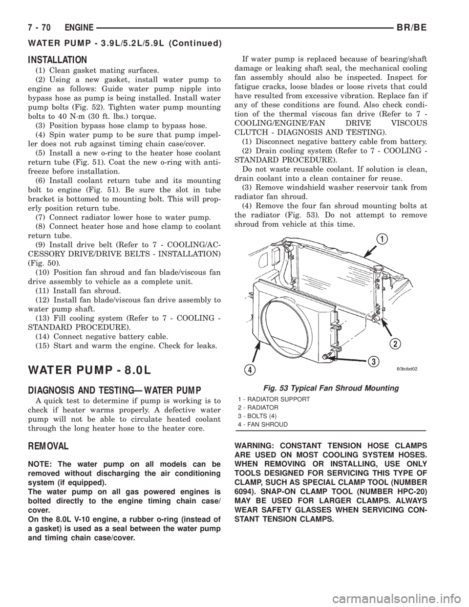
the radiator (Fig. 53). Do not attempt to remove
shroud from vehicle at this time.
WARNING: CONSTANT TENSION HOSE CLAMPS
ARE USED ON MOST COOLING SYSTEM HOSES.
WHEN REMOVING OR INSTALLING, USE ONLY
TOOLS DESIGNED FOR SERVICING THIS TYPE OF
CLAMP, SUCH AS SPECIAL CLAMP TOOL (NUMBER
6094). SNAP-ON CLAMP TOOL (NUMBER HPC-20)
MAY BE USED FOR LARGER CLAMPS. ALWAYS
WEAR SAFETY GLASSES WHEN SERVICING CON-
STANT TENSION CLAMPS.
Fig. 53 Typical Fan Shroud Mounting
1 - RADIATOR SUPPORT
2 - RADIATOR
3 - BOLTS (4)
4 - FAN SHROUD
7 - 70 ENGINEBR/BE
WATER PUMP - 3.9L/5.2L/5.9L (Continued)
Page 407 of 2889
(11) Remove heater hose at water pump fitting.
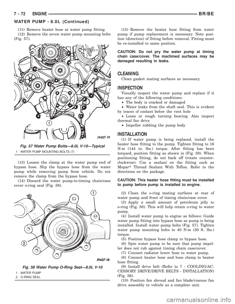
(12) Remove the seven water pump mounting bolts
(Fig. 57).
(13) Loosen the clamp at the water pump end of
bypass hose. Slip the bypass hose from the water
pump while removing pump from vehicle. Do not
remove the clamp from the bypass hose.
(14) Discard the water pump-to-timing chain/case
cover o-ring seal (Fig. 58).(15) Remove the heater hose fitting from water
pump if pump replacement is necessary. Note posi-
tion (direction) of fitting before removal. Fitting must
be re-installed to same position.
CAUTION: Do not pry the water pump at timing
chain case/cover. The machined surfaces may be
damaged resulting in leaks.
CLEANING
Clean gasket mating surfaces as necessary.
INSPECTION
Visually inspect the water pump and replace if it
has any of the following conditions:
²The body is cracked or damaged
²Water leaks from the shaft seal. This is evident
by traces of coolant below the vent hole
²Loose or rough turning bearing. Also inspect
thermal fan drive
²Impeller rubbing the pump body
INSTALLATION
(1) If water pump is being replaced, install the
heater hose fitting to the pump. Tighten fitting to 16
N´m (144 in. lbs.) torque. After fitting has been
torqued, position fitting as shown in (Fig. 59). When
positioning fitting, do not back off (rotate counter-
clockwise). Use a sealant on the fitting such as
MopartThread Sealant With Teflon. Refer to the
directions on the package.
CAUTION: This heater hose fitting must be installed
to pump before pump is installed to engine.
(2) Clean the o-ring mating surfaces at rear of
water pump and front of timing chain/case cover.
(3) Apply a small amount of petroleum jelly to
o-ring (Fig. 58). This will help retain o-ring to water
pump.
(4) Install water pump to engine as follows: Guide
water pump fitting into bypass hose as pump is being
installed. Install water pump bolts (Fig. 57). Tighten
water pump mounting bolts to 40 N´m (30 ft. lbs.)
torque.
(5) Position bypass hose clamp to bypass hose.
(6) Spin water pump to be sure that pump impel-
ler does not rub against timing chain case/cover.
(7) Connect radiator lower hose to water pump.
(8) Connect heater hose and hose clamp to heater
hose fitting.
(9) Install drive belt (Refer to 7 - COOLING/AC-
CESSORY DRIVE/DRIVE BELTS - INSTALLATION)
(Fig. 56).
(10) Position fan shroud and fan blade/viscous fan
drive assembly to vehicle as a complete unit.
Fig. 57 Water Pump BoltsÐ8.0L V-10ÐTypical
1 - WATER PUMP MOUNTING BOLTS (7)
Fig. 58 Water Pump O-Ring SealÐ8.0L V-10
1 - WATER PUMP
2 - O-RING SEAL
7 - 72 ENGINEBR/BE
WATER PUMP - 8.0L (Continued)
Page 408 of 2889
(11) Install fan shroud to radiator. Tighten bolts to
6 N´m (50 in. lbs.) torque.
(12) Install fan blade/viscous fan drive assembly to
water pump shaft.
(13) Fill cooling system (Refer to 7 - COOLING -
STANDARD PROCEDURE).
(14) Connect negative battery cable.
(15) Start and warm the engine. Check for leaks.
WATER PUMP - 5.9L DIESEL
DESCRIPTION
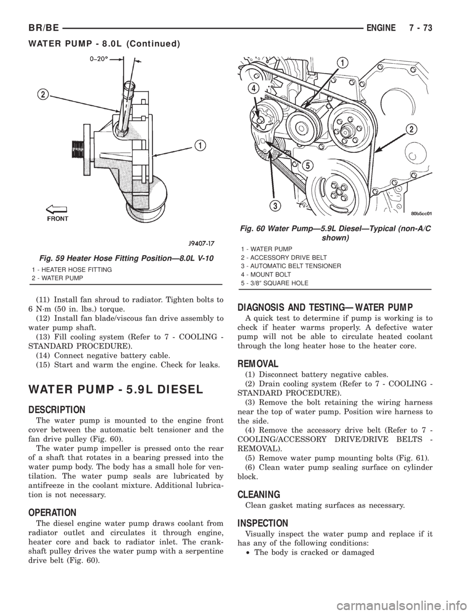
The water pump is mounted to the engine front
cover between the automatic belt tensioner and the
fan drive pulley (Fig. 60).
The water pump impeller is pressed onto the rear
of a shaft that rotates in a bearing pressed into the
water pump body. The body has a small hole for ven-
tilation. The water pump seals are lubricated by
antifreeze in the coolant mixture. Additional lubrica-
tion is not necessary.
OPERATION
The diesel engine water pump draws coolant from
radiator outlet and circulates it through engine,
heater core and back to radiator inlet. The crank-
shaft pulley drives the water pump with a serpentine
drive belt (Fig. 60).
DIAGNOSIS AND TESTINGÐWATER PUMP
A quick test to determine if pump is working is to
check if heater warms properly. A defective water
pump will not be able to circulate heated coolant
through the long heater hose to the heater core.
REMOVAL
(1) Disconnect battery negative cables.
(2) Drain cooling system (Refer to 7 - COOLING -
STANDARD PROCEDURE).
(3) Remove the bolt retaining the wiring harness
near the top of water pump. Position wire harness to
the side.
(4) Remove the accessory drive belt (Refer to 7 -
COOLING/ACCESSORY DRIVE/DRIVE BELTS -
REMOVAL).
(5) Remove water pump mounting bolts (Fig. 61).
(6) Clean water pump sealing surface on cylinder
block.
CLEANING
Clean gasket mating surfaces as necessary.
INSPECTION
Visually inspect the water pump and replace if it
has any of the following conditions:
²The body is cracked or damaged
Fig. 59 Heater Hose Fitting PositionÐ8.0L V-10
1 - HEATER HOSE FITTING
2 - WATER PUMP
Fig. 60 Water PumpÐ5.9L DieselÐTypical (non-A/C
shown)
1 - WATER PUMP
2 - ACCESSORY DRIVE BELT
3 - AUTOMATIC BELT TENSIONER
4 - MOUNT BOLT
5 - 3/89SQUARE HOLE
BR/BEENGINE 7 - 73
WATER PUMP - 8.0L (Continued)
Page 410 of 2889
(2) Do not waste reusable coolant. If the solution is
clean, drain the coolant into a clean container for
reuse.
(3) Remove upper radiator hose clamp at radiator.
A special clamp tool must be used to remove the con-
stant tension clamps. Remove hose at radiator.
(4) Disconnect throttle cable from clip at radiator
fan shroud.
(5) Unplug wiring harness from A/C compressor.
(6) Remove the air cleaner assembly.
(7) Remove accessory drive belt (Refer to 7 -
COOLING/ACCESSORY DRIVE/DRIVE BELTS -
REMOVAL).
(8)3.9L V-6 or 5.2/5.9L V-8 LDC-Gas:The drive
belt idler pulley must be removed to gain access to
one of the A/C compressor/generator bracket mount-
ing bolts. Remove the idler pulley bolt and remove
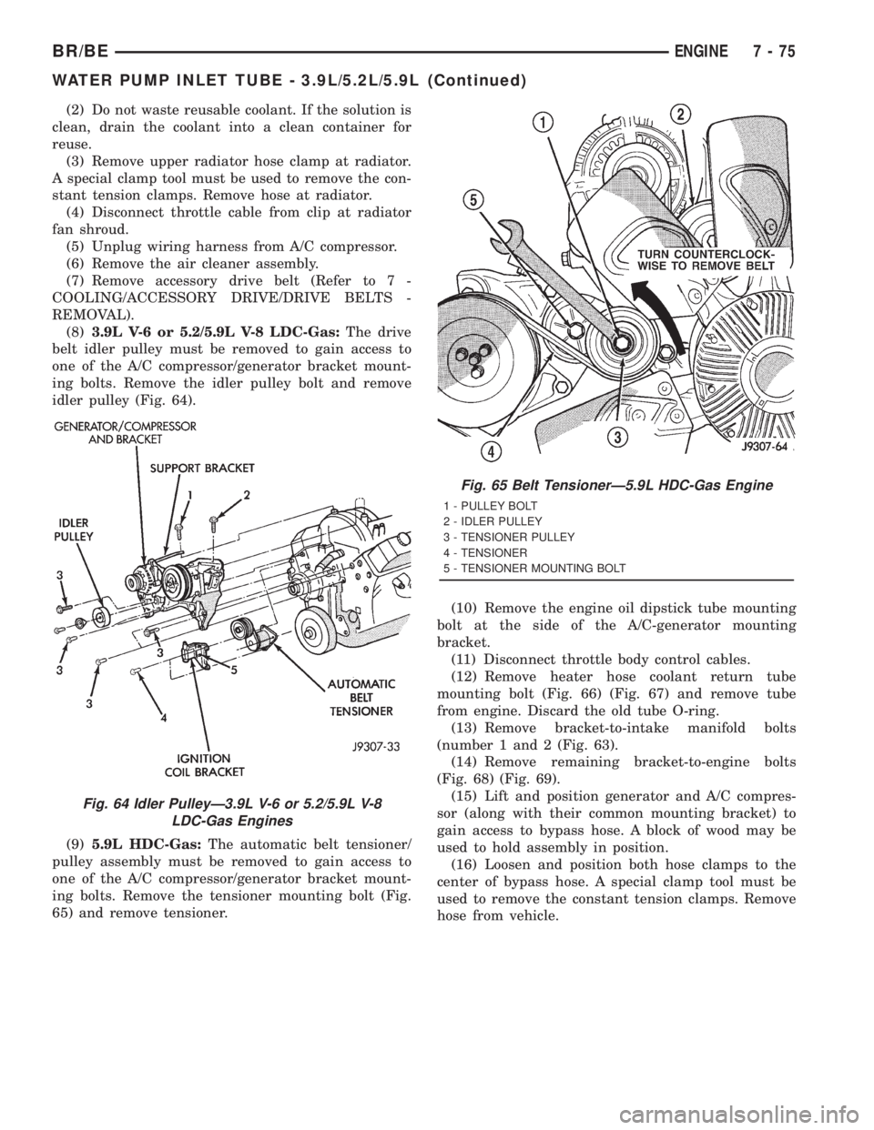
idler pulley (Fig. 64).
(9)5.9L HDC-Gas:The automatic belt tensioner/
pulley assembly must be removed to gain access to
one of the A/C compressor/generator bracket mount-
ing bolts. Remove the tensioner mounting bolt (Fig.
65) and remove tensioner.(10) Remove the engine oil dipstick tube mounting
bolt at the side of the A/C-generator mounting
bracket.
(11) Disconnect throttle body control cables.
(12) Remove heater hose coolant return tube
mounting bolt (Fig. 66) (Fig. 67) and remove tube
from engine. Discard the old tube O-ring.
(13) Remove bracket-to-intake manifold bolts
(number 1 and 2 (Fig. 63).
(14) Remove remaining bracket-to-engine bolts
(Fig. 68) (Fig. 69).
(15) Lift and position generator and A/C compres-
sor (along with their common mounting bracket) to
gain access to bypass hose. A block of wood may be
used to hold assembly in position.
(16) Loosen and position both hose clamps to the
center of bypass hose. A special clamp tool must be
used to remove the constant tension clamps. Remove
hose from vehicle.
Fig. 64 Idler PulleyÐ3.9L V-6 or 5.2/5.9L V-8
LDC-Gas Engines
Fig. 65 Belt TensionerÐ5.9L HDC-Gas Engine
1 - PULLEY BOLT
2 - IDLER PULLEY
3 - TENSIONER PULLEY
4 - TENSIONER
5 - TENSIONER MOUNTING BOLT
BR/BEENGINE 7 - 75
WATER PUMP INLET TUBE - 3.9L/5.2L/5.9L (Continued)
Page 412 of 2889
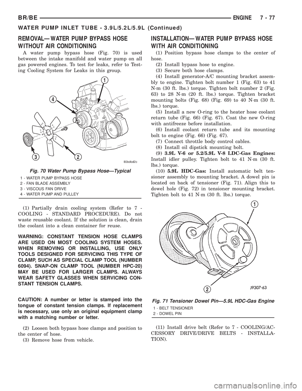
REMOVALÐWATER PUMP BYPASS HOSE
WITHOUT AIR CONDITIONING
A water pump bypass hose (Fig. 70) is used
between the intake manifold and water pump on all
gas powered engines. To test for leaks, refer to Test-
ing Cooling System for Leaks in this group.
(1) Partially drain cooling system (Refer to 7 -
COOLING - STANDARD PROCEDURE). Do not
waste reusable coolant. If the solution is clean, drain
the coolant into a clean container for reuse.
WARNING: CONSTANT TENSION HOSE CLAMPS
ARE USED ON MOST COOLING SYSTEM HOSES.
WHEN REMOVING OR INSTALLING, USE ONLY
TOOLS DESIGNED FOR SERVICING THIS TYPE OF
CLAMP, SUCH AS SPECIAL CLAMP TOOL (NUMBER
6094). SNAP-ON CLAMP TOOL (NUMBER HPC-20)
MAY BE USED FOR LARGER CLAMPS. ALWAYS
WEAR SAFETY GLASSES WHEN SERVICING CON-
STANT TENSION CLAMPS.
CAUTION: A number or letter is stamped into the
tongue of constant tension clamps. If replacement
is necessary, use only an original equipment clamp
with a matching number or letter.
(2) Loosen both bypass hose clamps and position to
the center of hose.
(3) Remove hose from vehicle.
INSTALLATIONÐWATER PUMP BYPASS HOSE
WITH AIR CONDITIONING
(1) Position bypass hose clamps to the center of
hose.
(2) Install bypass hose to engine.
(3) Secure both hose clamps.
(4) Install generator-A/C mounting bracket assem-
bly to engine. Tighten bolt number 1 (Fig. 63) to 41
N´m (30 ft. lbs.) torque. Tighten bolt number 2 (Fig.
63) to 28 N´m (20 ft. lbs.) torque. Tighten bracket
mounting bolts (Fig. 68) (Fig. 69) to 40 N´m (30 ft.
lbs.) torque.
(5) Install a new O-ring to the heater hose coolant
return tube (Fig. 66) (Fig. 67). Coat the new O-ring
with antifreeze before installation.
(6) Install coolant return tube and its mounting
bolt to engine (Fig. 66) (Fig. 67).
(7) Connect throttle body control cables.
(8) Install oil dipstick mounting bolt.
(9)3.9L V-6 or 5.2/5.9L V-8 LDC-Gas Engines:
Install idler pulley. Tighten bolt to 41 N´m (30 ft.
lbs.) torque.
(10)5.9L HDC-Gas:Install automatic belt ten-
sioner assembly to mounting bracket. A dowel pin is
located on back of tensioner (Fig. 71). Align this to
dowel hole (Fig. 72) in tensioner mounting bracket.
Tighten bolt to 41 N´m (30 ft. lbs.) torque.
(11) Install drive belt (Refer to 7 - COOLING/AC-
CESSORY DRIVE/DRIVE BELTS - INSTALLA-
TION).
Fig. 71 Tensioner Dowel PinÐ5.9L HDC-Gas Engine
1 - BELT TENSIONER
2 - DOWEL PIN
Fig. 70 Water Pump Bypass HoseÐTypical
1 - WATER PUMP BYPASS HOSE
2 - FAN BLADE ASSEMBLY
3 - VISCOUS FAN DRIVE
4 - WATER PUMP AND PULLEY
BR/BEENGINE 7 - 77
WATER PUMP INLET TUBE - 3.9L/5.2L/5.9L (Continued)
Page 424 of 2889
AUDIO
TABLE OF CONTENTS
page page
AUDIO
DESCRIPTION............................1
OPERATION.............................2
DIAGNOSIS AND TESTING..................2
AUDIO................................2
SPECIAL TOOLS..........................4
ANTENNA BODY & CABLE
DESCRIPTION............................4
OPERATION.............................4
DIAGNOSIS AND TESTING..................5
ANTENNA.............................5
REMOVAL...............................6
INSTALLATION............................7
RADIO CHOKE RELAY
DESCRIPTION............................8
OPERATION.............................8
DIAGNOSIS AND TESTING..................8
RADIO CHOKE RELAY....................8
REMOVAL...............................9
INSTALLATION............................9
INSTRUMENT PANEL ANTENNA CABLE
REMOVAL...............................9
INSTALLATION...........................10
RADIO
DESCRIPTION...........................10
OPERATION.............................10
DIAGNOSIS AND TESTING.................10
RADIO...............................10
REMOVAL..............................11
INSTALLATION...........................12
RADIO NOISE SUPPRESSION COMPONENTS
DESCRIPTION...........................12
DIAGNOSIS AND TESTING.................12
RADIO NOISE SUPPRESSION
COMPONENTS.........................12ENGINE-TO-BODY GROUND STRAP
REMOVAL..............................13
INSTALLATION...........................13
CAB-TO- BED GROUND STRAP
REMOVAL..............................14
INSTALLATION...........................14
HEATER CORE GROUND STRAP
REMOVAL..............................14
INSTALLATION...........................15
REMOTE SWITCHES
DESCRIPTION...........................15
OPERATION.............................15
DIAGNOSIS AND TESTING.................16
REMOTE SWITCHES....................16
REMOVAL..............................16
INSTALLATION...........................17
SPEAKER
DESCRIPTION...........................17
OPERATION.............................17
DIAGNOSIS AND TESTING.................18
SPEAKER............................18
A-PILLAR TWEETER SPEAKER
REMOVAL..............................19
INSTALLATION...........................19
FRONT DOOR SPEAKER
REMOVAL..............................20
INSTALLATION...........................20
REAR CAB SIDE PANEL SPEAKER
REMOVAL..............................20
INSTALLATION...........................21
REAR DOOR SPEAKER
REMOVAL..............................21
INSTALLATION...........................21
AUDIO
DESCRIPTION
An audio system is standard factory-installed equip-
ment on this model, unless the vehicle is ordered with
an available radio delete option. The standard equip-
ment audio system includes an AM/FM/cassette (RAS
sales code) receiver, and speakers in four locations. Sev-
eral combinations of radio receivers and speaker systems
are offered as optional equipment on this model. The
audio system uses an ignition switched source of battery
current so that the system will only operate when theignition switch is in the On or Accessory positions. The
audio system includes the following components:
²Antenna
²Clockspring (with remote radio switches only)
²Filter, choke and speaker relay (with premium
speaker system only)
²High-line or premium Central Timer Module
(CTM) (with remote radio switches)
²Radio noise suppression components
²Radio receiver
²Remote radio switches (optional with RAZ radio
receiver only)
²Speakers
BR/BEAUDIO 8A - 1
Page 429 of 2889
TEST 1
Test 1 determines if the antenna mast is insulated
from the base. Proceed as follows:
(1) Disconnect and isolate the antenna coaxial
cable connector from the radio receiver chassis.
(2) Connect one ohmmeter test lead to the tip of
the antenna mast. Connect the other test lead to the
antenna base. Check for continuity.
(3) There should be no continuity. If continuity is
found, replace the faulty or damaged antenna base
and cable assembly.
TEST 2
Test 2 checks the antenna for an open circuit as
follows:
(1) Disconnect the antenna coaxial cable connector
from the radio receiver chassis.
(2) Connect one ohmmeter test lead to the tip of
the antenna mast. Connect the other test lead to the
center pin of the antenna coaxial cable connector.
(3) Continuity should exist (the ohmmeter should
only register a fraction of an ohm). High or infinite
resistance indicates damage to the base and cable
assembly. Replace the faulty or damaged antenna
base and cable, if required.
TEST 3
Test 3 checks the condition of the vehicle body
ground connection. This test should be performed
with the battery positive cable removed from the bat-
tery. Disconnect both battery cables, the negative
cable first. Reconnect the battery negative cable and
perform the test as follows:(1) Connect one ohmmeter test lead to the vehicle
fender. Connect the other test lead to the battery
negative terminal post.
(2) The resistance should be less than one ohm.
(3) If the resistance is more than one ohm, check
the braided ground strap(s) connected to the engine
and the vehicle body for being loose, corroded, or
damaged. Repair the ground strap connections, if
required.
TEST 4
Test 4 checks the condition of the ground between
the antenna base and the vehicle body as follows:
(1) Connect one ohmmeter test lead to the vehicle
fender. Connect the other test lead to the outer crimp
on the antenna coaxial cable connector.
(2) The resistance should be less then one ohm.
(3) If the resistance is more then one ohm, clean
and/or tighten the antenna base to fender mounting
hardware.
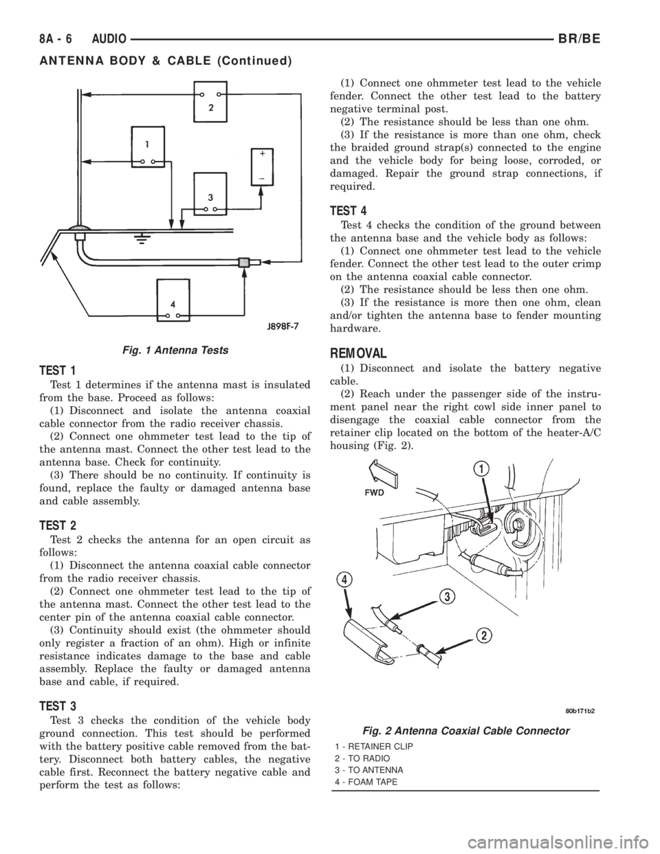
REMOVAL
(1) Disconnect and isolate the battery negative
cable.
(2) Reach under the passenger side of the instru-
ment panel near the right cowl side inner panel to
disengage the coaxial cable connector from the
retainer clip located on the bottom of the heater-A/C
housing (Fig. 2).
Fig. 1 Antenna Tests
Fig. 2 Antenna Coaxial Cable Connector
1 - RETAINER CLIP
2 - TO RADIO
3 - TO ANTENNA
4 - FOAM TAPE
8A - 6 AUDIOBR/BE
ANTENNA BODY & CABLE (Continued)
Page 431 of 2889
securely to the connector on the end of the antenna
cable being installed into the instrument panel. This
cord will be used to pull or ªfishº the cable back into
position.
(2) Using the cord or twine, pull the antenna cable
through the radio receiver opening from under the
instrument panel.
(3) Install the radio receiver onto the instrument
panel.
(4) Reach through the glove box opening to engage
the antenna cable with the retainer clips on the back
of the instrument panel.
(5) Install the glove box onto the instrument panel.
(6) Untie the cord or twine from the instrument
panel antenna cable connector.
(7) Reach under the passenger side of the instru-
ment panel near the right cowl side inner panel to
reconnect the two halves of the radio antenna coaxial
cable connector. Wrap the connection with a piece of
foam tape.
(8) Engage the coaxial cable connector with the
retainer clip located on the bottom of the heater-A/C
housing.
(9) Reconnect the battery negative cable.
RADIO CHOKE RELAY
DESCRIPTION
Models equipped with the Infinity premium
speaker package have a filter, choke, and speaker
relay unit. The filter, choke, and speaker relay unit is
mounted to the lower instrument panel center brace,
inboard of the Central Timer Module (CTM) and
directly above the 16-way data link connector. The
filter, choke, and speaker relay unit can be accessed
for service without instrument panel disassembly or
removal.
The filter, choke, and speaker relay unit should be
checked if there is no sound output noted from the
speakers. The filter, choke, and speaker relay unit
cannot be repaired or adjusted and, if faulty or dam-
aged, the unit must be replaced.
OPERATION
The filter, choke, and speaker relay unit is used to
control the supply of fused battery current to the
front door speaker-mounted dual amplifiers. The
speaker relay is energized by a fused 12 volt output
from the radio receiver whenever the radio is turned
on. For complete circuit diagrams, refer to the appro-
priate wiring information. The wiring information
includes wiring diagrams, proper wire and connector
repair procedures, details of wire harness routing
and retention, connector pin-out information andlocation views for the various wire harness connec-
tors, splices and grounds.
DIAGNOSIS AND TESTING - RADIO CHOKE
RELAY
The filter, choke and speaker relay is used to
switch power to the individual speaker amplifiers
used with the Infinity premium speaker package.
The choke and relay are serviced only as a unit. If all
of the speakers are inoperative the filter, choke and
speaker relay unit should be considered suspect.
However, before replacement make the following
checks of the filter, choke and speaker relay circuits.
For complete circuit diagrams, refer to the appropri-
ate wiring information. The wiring information
includes wiring diagrams, proper wire and connector
repair procedures, details of wire harness routing
and retention, connector pin-out information and
location views for the various wire harness connec-
tors, splices and grounds.
(1)
Check the fused B(+) fuse in the junction block.
If OK, go to Step 2. If not OK, replace the faulty fuse.
(2) Check for battery voltage at the fused B(+) fuse
in the junction block. If OK, go to Step 3. If not OK,
repair the open fused B(+) circuit to the battery as
required.
(3) Disconnect the instrument panel wire harness
connector from the filter, choke and speaker relay
unit. Check for battery voltage at the fused B(+) cir-
cuit cavity of the instrument panel wire harness con-
nector for the filter, choke and speaker relay unit. If
OK, go to Step 4. If not OK, repair the open fused
B(+) circuit to the junction block fuse as required.
(4) Probe the ground circuit cavity of the instru-
ment panel wire harness connector for the filter,
choke and speaker relay unit. Check for continuity to
a good ground. There should be continuity. If OK, go
to Step 5. If not OK, repair the open ground circuit to
ground as required.
(5) Turn the ignition switch to the On position and
turn the radio on. Check for battery voltage at the
radio 12-volt output circuit cavity of the instrument
panel wire harness connector for the filter, choke and
speaker relay unit. If OK, go to Step 6. If not OK,
repair the open radio 12-volt output circuit to the
radio as required.
(6) Turn the radio and ignition switches to the Off
position. Reconnect the instrument panel wire har-
ness connector to the filter, choke and speaker relay
unit. Check for battery voltage at the amplified
speaker (+) circuit cavity of the instrument panel
wire harness connector for the filter, choke and
speaker relay unit. There should be zero volts. Turn
the ignition and radio switches to the On position.
8A - 8 AUDIOBR/BE
ANTENNA BODY & CABLE (Continued)