2001 DODGE RAM heater
[x] Cancel search: heaterPage 432 of 2889
There should now be battery voltage. If OK, repair
the open amplified speaker (+) circuits to the speak-
er-mounted amplifiers as required. If not OK, replace
the faulty filter, choke and speaker relay unit.
REMOVAL
(1) Disconnect and isolate the battery negative
cable.
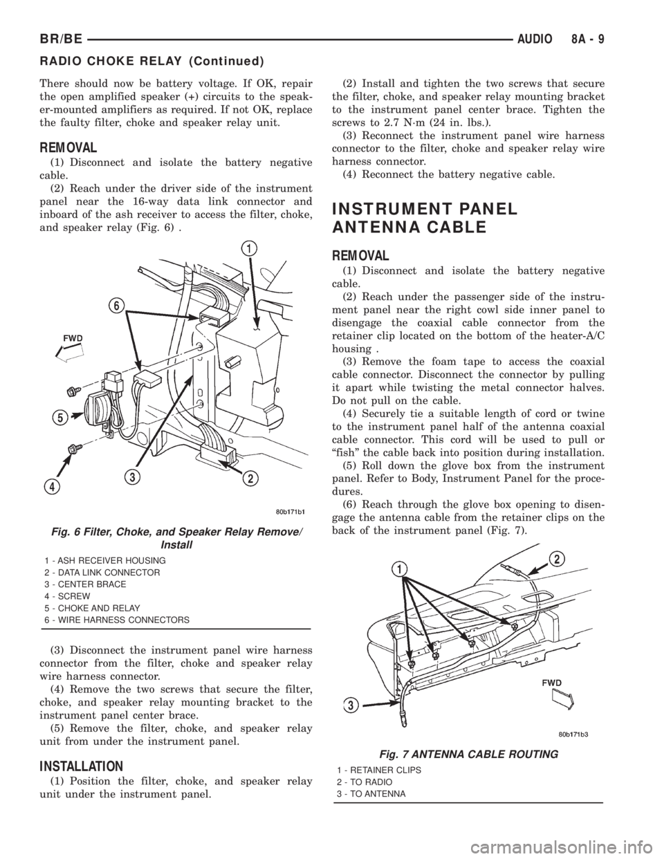
(2) Reach under the driver side of the instrument
panel near the 16-way data link connector and
inboard of the ash receiver to access the filter, choke,
and speaker relay (Fig. 6) .
(3) Disconnect the instrument panel wire harness
connector from the filter, choke and speaker relay
wire harness connector.
(4) Remove the two screws that secure the filter,
choke, and speaker relay mounting bracket to the
instrument panel center brace.
(5) Remove the filter, choke, and speaker relay
unit from under the instrument panel.
INSTALLATION
(1) Position the filter, choke, and speaker relay
unit under the instrument panel.(2) Install and tighten the two screws that secure
the filter, choke, and speaker relay mounting bracket
to the instrument panel center brace. Tighten the
screws to 2.7 N´m (24 in. lbs.).
(3) Reconnect the instrument panel wire harness
connector to the filter, choke and speaker relay wire
harness connector.
(4) Reconnect the battery negative cable.
INSTRUMENT PANEL
ANTENNA CABLE
REMOVAL
(1) Disconnect and isolate the battery negative
cable.
(2) Reach under the passenger side of the instru-
ment panel near the right cowl side inner panel to
disengage the coaxial cable connector from the
retainer clip located on the bottom of the heater-A/C
housing .
(3) Remove the foam tape to access the coaxial
cable connector. Disconnect the connector by pulling
it apart while twisting the metal connector halves.
Do not pull on the cable.
(4) Securely tie a suitable length of cord or twine
to the instrument panel half of the antenna coaxial
cable connector. This cord will be used to pull or
ªfishº the cable back into position during installation.
(5) Roll down the glove box from the instrument
panel. Refer to Body, Instrument Panel for the proce-
dures.
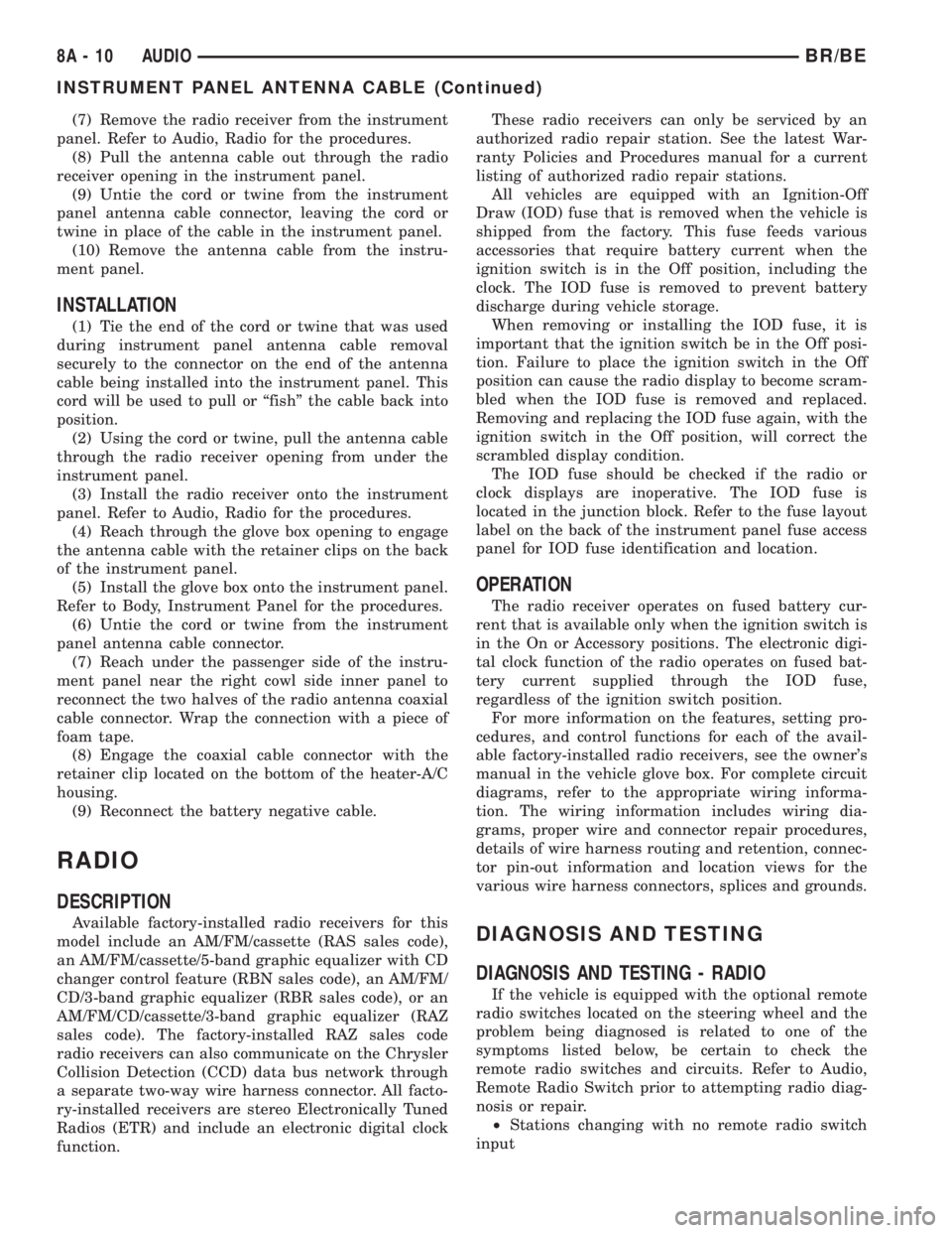
(6) Reach through the glove box opening to disen-
gage the antenna cable from the retainer clips on the
back of the instrument panel (Fig. 7).
Fig. 6 Filter, Choke, and Speaker Relay Remove/
Install
1 - ASH RECEIVER HOUSING
2 - DATA LINK CONNECTOR
3 - CENTER BRACE
4 - SCREW
5 - CHOKE AND RELAY
6 - WIRE HARNESS CONNECTORS
Fig. 7 ANTENNA CABLE ROUTING
1 - RETAINER CLIPS
2 - TO RADIO
3 - TO ANTENNA
BR/BEAUDIO 8A - 9
RADIO CHOKE RELAY (Continued)
Page 433 of 2889
(7) Remove the radio receiver from the instrument
panel. Refer to Audio, Radio for the procedures.
(8) Pull the antenna cable out through the radio
receiver opening in the instrument panel.
(9) Untie the cord or twine from the instrument
panel antenna cable connector, leaving the cord or
twine in place of the cable in the instrument panel.
(10) Remove the antenna cable from the instru-
ment panel.
INSTALLATION
(1) Tie the end of the cord or twine that was used
during instrument panel antenna cable removal
securely to the connector on the end of the antenna
cable being installed into the instrument panel. This
cord will be used to pull or ªfishº the cable back into
position.
(2) Using the cord or twine, pull the antenna cable
through the radio receiver opening from under the
instrument panel.
(3) Install the radio receiver onto the instrument
panel. Refer to Audio, Radio for the procedures.
(4) Reach through the glove box opening to engage
the antenna cable with the retainer clips on the back
of the instrument panel.
(5) Install the glove box onto the instrument panel.
Refer to Body, Instrument Panel for the procedures.
(6) Untie the cord or twine from the instrument
panel antenna cable connector.
(7) Reach under the passenger side of the instru-
ment panel near the right cowl side inner panel to
reconnect the two halves of the radio antenna coaxial
cable connector. Wrap the connection with a piece of
foam tape.
(8) Engage the coaxial cable connector with the
retainer clip located on the bottom of the heater-A/C
housing.
(9) Reconnect the battery negative cable.
RADIO
DESCRIPTION
Available factory-installed radio receivers for this
model include an AM/FM/cassette (RAS sales code),
an AM/FM/cassette/5-band graphic equalizer with CD
changer control feature (RBN sales code), an AM/FM/
CD/3-band graphic equalizer (RBR sales code), or an
AM/FM/CD/cassette/3-band graphic equalizer (RAZ
sales code). The factory-installed RAZ sales code
radio receivers can also communicate on the Chrysler
Collision Detection (CCD) data bus network through
a separate two-way wire harness connector. All facto-
ry-installed receivers are stereo Electronically Tuned
Radios (ETR) and include an electronic digital clock
function.These radio receivers can only be serviced by an
authorized radio repair station. See the latest War-
ranty Policies and Procedures manual for a current
listing of authorized radio repair stations.
All vehicles are equipped with an Ignition-Off
Draw (IOD) fuse that is removed when the vehicle is
shipped from the factory. This fuse feeds various
accessories that require battery current when the
ignition switch is in the Off position, including the
clock. The IOD fuse is removed to prevent battery
discharge during vehicle storage.
When removing or installing the IOD fuse, it is
important that the ignition switch be in the Off posi-
tion. Failure to place the ignition switch in the Off
position can cause the radio display to become scram-
bled when the IOD fuse is removed and replaced.
Removing and replacing the IOD fuse again, with the
ignition switch in the Off position, will correct the
scrambled display condition.
The IOD fuse should be checked if the radio or
clock displays are inoperative. The IOD fuse is
located in the junction block. Refer to the fuse layout
label on the back of the instrument panel fuse access
panel for IOD fuse identification and location.
OPERATION
The radio receiver operates on fused battery cur-
rent that is available only when the ignition switch is
in the On or Accessory positions. The electronic digi-
tal clock function of the radio operates on fused bat-
tery current supplied through the IOD fuse,
regardless of the ignition switch position.
For more information on the features, setting pro-
cedures, and control functions for each of the avail-
able factory-installed radio receivers, see the owner's
manual in the vehicle glove box. For complete circuit
diagrams, refer to the appropriate wiring informa-
tion. The wiring information includes wiring dia-
grams, proper wire and connector repair procedures,
details of wire harness routing and retention, connec-
tor pin-out information and location views for the
various wire harness connectors, splices and grounds.
DIAGNOSIS AND TESTING
DIAGNOSIS AND TESTING - RADIO
If the vehicle is equipped with the optional remote
radio switches located on the steering wheel and the
problem being diagnosed is related to one of the
symptoms listed below, be certain to check the
remote radio switches and circuits. Refer to Audio,
Remote Radio Switch prior to attempting radio diag-
nosis or repair.
²Stations changing with no remote radio switch
input
8A - 10 AUDIOBR/BE
INSTRUMENT PANEL ANTENNA CABLE (Continued)
Page 435 of 2889
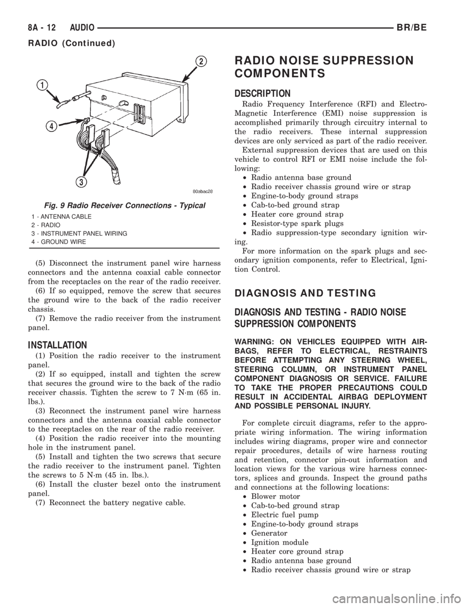
(5) Disconnect the instrument panel wire harness
connectors and the antenna coaxial cable connector
from the receptacles on the rear of the radio receiver.
(6) If so equipped, remove the screw that secures
the ground wire to the back of the radio receiver
chassis.
(7) Remove the radio receiver from the instrument
panel.
INSTALLATION
(1) Position the radio receiver to the instrument
panel.
(2) If so equipped, install and tighten the screw
that secures the ground wire to the back of the radio
receiver chassis. Tighten the screw to 7 N´m (65 in.
lbs.).
(3) Reconnect the instrument panel wire harness
connectors and the antenna coaxial cable connector
to the receptacles on the rear of the radio receiver.
(4) Position the radio receiver into the mounting
hole in the instrument panel.
(5) Install and tighten the two screws that secure
the radio receiver to the instrument panel. Tighten
the screws to 5 N´m (45 in. lbs.).
(6) Install the cluster bezel onto the instrument
panel.
(7) Reconnect the battery negative cable.
RADIO NOISE SUPPRESSION
COMPONENTS
DESCRIPTION
Radio Frequency Interference (RFI) and Electro-
Magnetic Interference (EMI) noise suppression is
accomplished primarily through circuitry internal to
the radio receivers. These internal suppression
devices are only serviced as part of the radio receiver.
External suppression devices that are used on this
vehicle to control RFI or EMI noise include the fol-
lowing:
²Radio antenna base ground
²Radio receiver chassis ground wire or strap
²Engine-to-body ground straps
²Cab-to-bed ground strap
²Heater core ground strap
²Resistor-type spark plugs
²Radio suppression-type secondary ignition wir-
ing.
For more information on the spark plugs and sec-
ondary ignition components, refer to Electrical, Igni-
tion Control.
DIAGNOSIS AND TESTING
DIAGNOSIS AND TESTING - RADIO NOISE
SUPPRESSION COMPONENTS
WARNING: ON VEHICLES EQUIPPED WITH AIR-
BAGS, REFER TO ELECTRICAL, RESTRAINTS
BEFORE ATTEMPTING ANY STEERING WHEEL,
STEERING COLUMN, OR INSTRUMENT PANEL
COMPONENT DIAGNOSIS OR SERVICE. FAILURE
TO TAKE THE PROPER PRECAUTIONS COULD
RESULT IN ACCIDENTAL AIRBAG DEPLOYMENT
AND POSSIBLE PERSONAL INJURY.
For complete circuit diagrams, refer to the appro-
priate wiring information. The wiring information
includes wiring diagrams, proper wire and connector
repair procedures, details of wire harness routing
and retention, connector pin-out information and
location views for the various wire harness connec-
tors, splices and grounds. Inspect the ground paths
and connections at the following locations:
²Blower motor
²Cab-to-bed ground strap
²Electric fuel pump
²Engine-to-body ground straps
²Generator
²Ignition module
²Heater core ground strap
²Radio antenna base ground
²Radio receiver chassis ground wire or strap
Fig. 9 Radio Receiver Connections - Typical
1 - ANTENNA CABLE
2 - RADIO
3 - INSTRUMENT PANEL WIRING
4 - GROUND WIRE
8A - 12 AUDIOBR/BE
RADIO (Continued)
Page 437 of 2889
(3) For the right side only on vehicles equipped
with a 3.9L, 5.2L or 5.9L engine, position the engine-
to-body ground strap eyelet over the right rear valve
cover stud.
(4) For the right side only on vehicles equipped
with a 3.9L, 5.2L or 5.9L engine, install and tighten
the nut that secures the engine-to-body ground strap
eyelet to the right rear valve cover stud. Tighten the
nut to 3.9 N´m (35 in. lbs.).
(5) Position the engine-to-body ground strap to the
dash panel.
(6) Install and tighten the screw that secures the
engine-to-body ground strap eyelet to the dash panel.
Tighten the screw to 3.9 N´m (35 in. lbs.).
CAB-TO- BED GROUND STRAP
REMOVAL
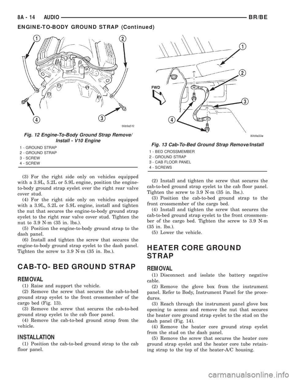
(1) Raise and support the vehicle.
(2) Remove the screw that secures the cab-to-bed
ground strap eyelet to the front crossmember of the
cargo bed (Fig. 13).
(3) Remove the screw that secures the cab-to-bed
ground strap eyelet to the cab floor panel.
(4) Remove the cab-to-bed ground strap from the
vehicle.
INSTALLATION
(1) Position the cab-to-bed ground strap to the cab
floor panel.(2) Install and tighten the screw that secures the
cab-to-bed ground strap eyelet to the cab floor panel.
Tighten the screw to 3.9 N´m (35 in. lbs.).
(3) Position the cab-to-bed ground strap to the
front crossmember of the cargo bed.
(4) Install and tighten the screw that secures the
cab-to-bed ground strap eyelet to the front crossmem-
ber of the cargo bed. Tighten the screw to 3.9 N´m
(35 in. lbs.).
(5) Lower the vehicle.
HEATER CORE GROUND
STRAP
REMOVAL
(1) Disconnect and isolate the battery negative
cable.
(2) Remove the glove box from the instrument
panel. Refer to Body, Instrument Panel for the proce-
dures.
(3) Reach through the instrument panel glove box
opening to access and remove the nut that secures
the heater core ground strap eyelet to the stud on the
dash panel (Fig. 14).
(4) Remove the heater core ground strap eyelet
from the stud on the dash panel.
(5) Remove the screw that secures the heater core
ground strap eyelet and the heater core tube retain-
ing strap to the top of the heater-A/C housing.
Fig. 12 Engine-To-Body Ground Strap Remove/
Install - V10 Engine
1 - GROUND STRAP
2 - GROUND STRAP
3 - SCREW
4 - SCREWFig. 13 Cab-To-Bed Ground Strap Remove/Install
1 - BED CROSSMEMBER
2 - GROUND STRAP
3 - CAB FLOOR PANEL
4 - SCREWS
8A - 14 AUDIOBR/BE
ENGINE-TO-BODY GROUND STRAP (Continued)
Page 438 of 2889
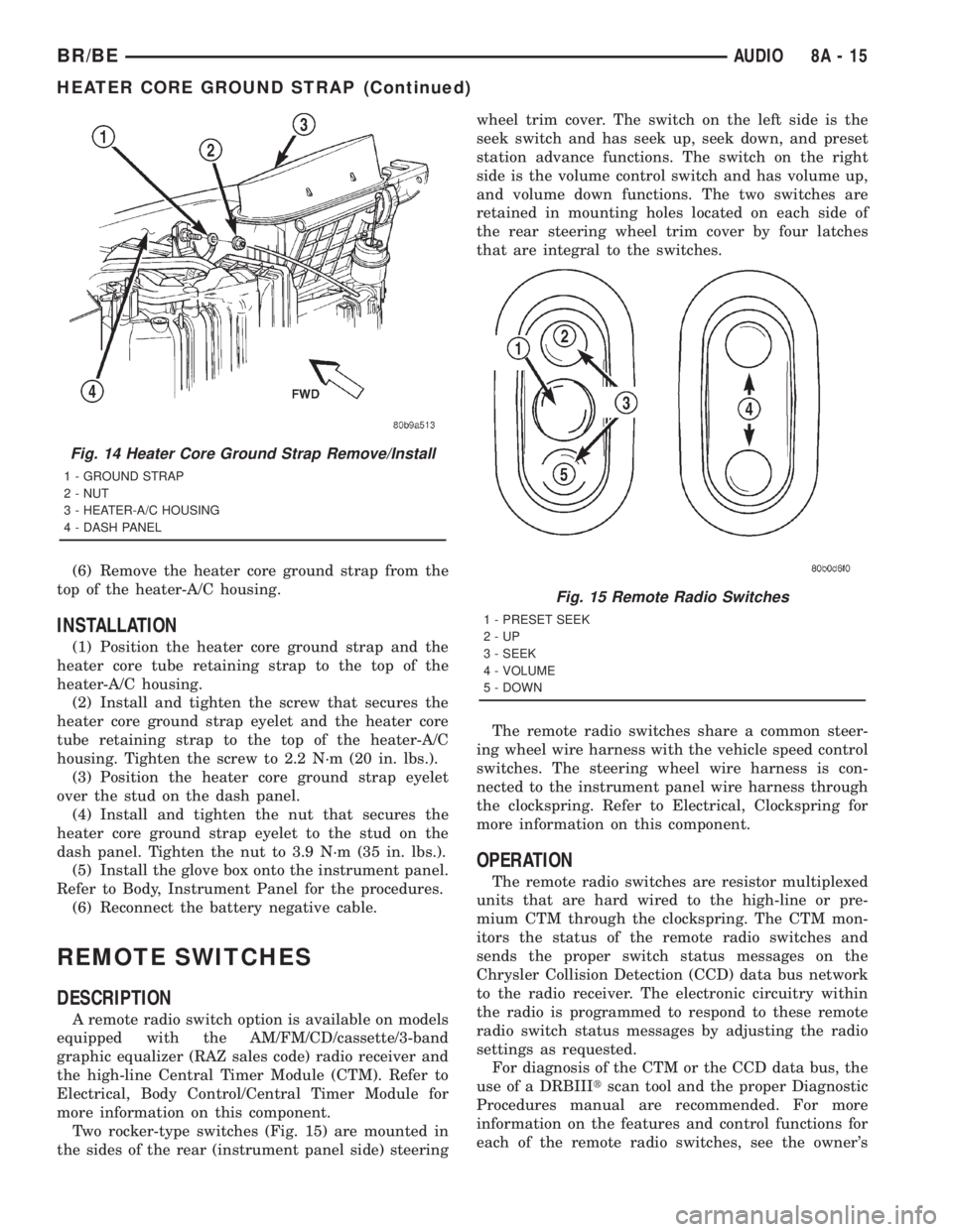
(6) Remove the heater core ground strap from the
top of the heater-A/C housing.
INSTALLATION
(1) Position the heater core ground strap and the
heater core tube retaining strap to the top of the
heater-A/C housing.
(2) Install and tighten the screw that secures the
heater core ground strap eyelet and the heater core
tube retaining strap to the top of the heater-A/C
housing. Tighten the screw to 2.2 N´m (20 in. lbs.).
(3) Position the heater core ground strap eyelet
over the stud on the dash panel.
(4) Install and tighten the nut that secures the
heater core ground strap eyelet to the stud on the
dash panel. Tighten the nut to 3.9 N´m (35 in. lbs.).
(5) Install the glove box onto the instrument panel.
Refer to Body, Instrument Panel for the procedures.
(6) Reconnect the battery negative cable.
REMOTE SWITCHES
DESCRIPTION
A remote radio switch option is available on models
equipped with the AM/FM/CD/cassette/3-band
graphic equalizer (RAZ sales code) radio receiver and
the high-line Central Timer Module (CTM). Refer to
Electrical, Body Control/Central Timer Module for
more information on this component.
Two rocker-type switches (Fig. 15) are mounted in
the sides of the rear (instrument panel side) steeringwheel trim cover. The switch on the left side is the
seek switch and has seek up, seek down, and preset
station advance functions. The switch on the right
side is the volume control switch and has volume up,
and volume down functions. The two switches are
retained in mounting holes located on each side of
the rear steering wheel trim cover by four latches
that are integral to the switches.
The remote radio switches share a common steer-
ing wheel wire harness with the vehicle speed control
switches. The steering wheel wire harness is con-
nected to the instrument panel wire harness through
the clockspring. Refer to Electrical, Clockspring for
more information on this component.
OPERATION
The remote radio switches are resistor multiplexed
units that are hard wired to the high-line or pre-
mium CTM through the clockspring. The CTM mon-
itors the status of the remote radio switches and
sends the proper switch status messages on the
Chrysler Collision Detection (CCD) data bus network
to the radio receiver. The electronic circuitry within
the radio is programmed to respond to these remote
radio switch status messages by adjusting the radio
settings as requested.
For diagnosis of the CTM or the CCD data bus, the
use of a DRBIIItscan tool and the proper Diagnostic
Procedures manual are recommended. For more
information on the features and control functions for
each of the remote radio switches, see the owner's
Fig. 14 Heater Core Ground Strap Remove/Install
1 - GROUND STRAP
2 - NUT
3 - HEATER-A/C HOUSING
4 - DASH PANEL
Fig. 15 Remote Radio Switches
1 - PRESET SEEK
2-UP
3 - SEEK
4 - VOLUME
5 - DOWN
BR/BEAUDIO 8A - 15
HEATER CORE GROUND STRAP (Continued)
Page 465 of 2889

NOTE: ECM Outputs:
After inputs are received by the ECM, certain sen-
sors, switches and components are controlled or reg-
ulated by the ECM. These are consideredECM
Outputs.These outputs are for:
²CCD bus (+) circuits
²CCD bus (-) circuits
²CKP and APPS outputs to the PCM
²Data link connection for DRB scan tool
²Five volt sensor supply
²Fuel injection pump
²Fuel injection pump relay
²(FPCM) Fuel Pump Control Module
²Fuel transfer (lift) pump
²Intake manifold air heater relays #1 and #2 con-
trol circuits
²Malfunction indicator lamp (Check engine lamp)
²Oil pressure gauge/warning lamp
²PCM
²Wait-to-start warning lamp
²Water-In-Fuel (WIF) warning lamp
REMOVAL
The ECM is bolted to the engine block behind the
fuel filter (Fig. 16).
(1) Record any Diagnostic Trouble Codes (DTC's)
found in the PCM or ECM.To avoid possible voltage spike damage to either
the Powertrain Control Module (PCM) or ECM, igni-
tion key must be off, and negative battery cables
must be disconnected before unplugging ECM con-
nectors.
(2) Disconnect both negative battery cables at both
batteries.
(3) Remove 50±way electrical connector bolt at
ECM (Fig. 16). Note: Connector bolt is female 4mm
hex head. To remove bolt, use a ball-hex bit or ball-
hex screwdriver such as Snap-Ont4mm SDABM4
(5/32º may also be used). As bolt is being removed,
very carefully remove connector from ECM.
(4) Remove three ECM mounting bolts and remove
ECM from vehicle.
INSTALLATION
Do not apply paint to back of ECM. Poor ground
will result.
(1) Clean ECM mounting points at engine block.
(2) Position ECM to engine block and install 3
mounting bolts. Tighten bolts to 24 N´m (18 ft. lbs.).
(3) Check pin connectors in ECM and 50±way con-
nector for corrosion or damage. Repair as necessary.
(4) Clean pins in 50±way electrical connector with
a quick-dry electrical contact cleaner.
(5) Very carefully install 50±way connector to
ECM. Tighten connector hex bolt.
(6) Install battery cables.
(7)Turn key to ON position. Without starting
engine, slowly press throttle pedal to floor and
then slowly release. This step must be done
(one time) to ensure accelerator pedal position
sensor calibration has been learned by ECM. If
not done, possible DTC's may be set.
(8) Use DRB scan tool to erase any stored compan-
ion DTC's from PCM.
POWERTRAIN CONTROL
MODULE
DESCRIPTION - PCM
The Powertrain Control Module (PCM) is located
in the engine compartment (Fig. 17). The PCM is
referred to as JTEC.
DESCRIPTION - MODES OF OPERATION
As input signals to the Powertrain Control Module
(PCM) change, the PCM adjusts its response to the
output devices. For example, the PCM must calculate
different injector pulse width and ignition timing for
idle than it does for wide open throttle (WOT).
The PCM will operate in two different modes:
Open Loop and Closed Loop.
Fig. 16 Engine Control Module (ECM) Location and
Mounting
1 - ENGINE CONTROL MODULE (ECM)
2 - HEX HEADED BOLT
3 - 50-WAY CONNECTOR
4 - FUEL TRANSFER PUMP
5 - MOUNTING BOLTS (3)
8E - 14 ELECTRONIC CONTROL MODULESBR/BE
ENGINE CONTROL MODULE (Continued)
Page 466 of 2889

During Open Loop modes, the PCM receives input
signals and responds only according to preset PCM
programming. Input from the oxygen (O2S) sensors
is not monitored during Open Loop modes.
During Closed Loop modes, the PCM will monitor
the oxygen (O2S) sensors input. This input indicates
to the PCM whether or not the calculated injector
pulse width results in the ideal air-fuel ratio. This
ratio is 14.7 parts air-to-1 part fuel. By monitoring
the exhaust oxygen content through the O2S sensor,
the PCM can fine tune the injector pulse width. This
is done to achieve optimum fuel economy combined
with low emission engine performance.
The fuel injection system has the following modes
of operation:
²Ignition switch ON
²Engine start-up (crank)
²Engine warm-up
²Idle
²Cruise
²Acceleration
²Deceleration
²Wide open throttle (WOT)
²Ignition switch OFF
The ignition switch On, engine start-up (crank),
engine warm-up, acceleration, deceleration and wide
open throttle modes are Open Loop modes. The idle
and cruise modes, (with the engine at operating tem-
perature) are Closed Loop modes.
IGNITION SWITCH (KEY-ON) MODE
This is an Open Loop mode. When the fuel system
is activated by the ignition switch, the following
actions occur:²The PCM pre-positions the idle air control (IAC)
motor.
²The PCM determines atmospheric air pressure
from the MAP sensor input to determine basic fuel
strategy.
²The PCM monitors the engine coolant tempera-
ture sensor input. The PCM modifies fuel strategy
based on this input.
²Intake manifold air temperature sensor input is
monitored.
²Throttle position sensor (TPS) is monitored.
²The auto shutdown (ASD) relay is energized by
the PCM for approximately three seconds.
²The fuel pump is energized through the fuel
pump relay by the PCM. The fuel pump will operate
for approximately three seconds unless the engine is
operating or the starter motor is engaged.
²The O2S sensor heater element is energized via
the ASD relay. The O2S sensor input is not used by
the PCM to calibrate air-fuel ratio during this mode
of operation.
ENGINE START-UP MODE
This is an Open Loop mode. The following actions
occur when the starter motor is engaged.
The PCM receives inputs from:
²Battery voltage
²Engine coolant temperature sensor
²Crankshaft position sensor
²Intake manifold air temperature sensor
²Manifold absolute pressure (MAP) sensor
²Throttle position sensor (TPS)
²Starter motor relay
²Camshaft position sensor signal
The PCM monitors the crankshaft position sensor.
If the PCM does not receive a crankshaft position
sensor signal within 3 seconds of cranking the
engine, it will shut down the fuel injection system.
The fuel pump is activated by the PCM through
the fuel pump relay.
Voltage is applied to the fuel injectors with the
ASD relay via the PCM. The PCM will then control
the injection sequence and injector pulse width by
turning the ground circuit to each individual injector
on and off.
The PCM determines the proper ignition timing
according to input received from the crankshaft posi-
tion sensor.
ENGINE WARM-UP MODE
This is an Open Loop mode. During engine warm-
up, the PCM receives inputs from:
²Battery voltage
²Crankshaft position sensor
²Engine coolant temperature sensor
²Intake manifold air temperature sensor
Fig. 17 PCM Location
1 - PCM MOUNTING BOLTS (3)
2 - POWERTRAIN CONTROL MODULE (PCM)
3 - (3) 32±WAY CONNECTORS
BR/BEELECTRONIC CONTROL MODULES 8E - 15
POWERTRAIN CONTROL MODULE (Continued)
Page 491 of 2889
DIESEL ENGINE
Diesel engine models feature a clamping type
female battery terminal made of soft lead die cast
onto one end of the battery cable wire. A square
headed pinch-bolt and hex nut are installed at the
open end of the female battery terminal clamp. The
pinch-bolt on the left side battery positive cable
female terminal clamp also has a stud extending
from the head of the bolt. Large eyelet type terminals
are crimped onto the opposite end of the battery
cable wire and then solder-dipped. The battery posi-
tive cable wires have a red insulating jacket to pro-
vide visual identification and feature a larger female
battery terminal clamp to allow connection to the
larger battery positive terminal post. The battery
negative cable wires have a black insulating jacket
and a smaller female battery terminal clamp.
OPERATION
The battery cables connect the battery terminal
posts to the vehicle electrical system. These cables
also provide a return path for electrical current gen-
erated by the charging system for restoring the volt-
age potential of the battery. The female battery
terminal clamps on the ends of the battery cable
wires provide a strong and reliable connection of the
battery cable to the battery terminal posts. The ter-
minal pinch bolts allow the female terminal clamps
to be tightened around the male terminal posts on
the top of the battery. The eyelet terminals secured
to the ends of the battery cable wires opposite the
female battery terminal clamps provide secure and
reliable connection of the battery to the vehicle elec-
trical system.
GASOLINE ENGINE
The battery positive cable terminal clamp is
crimped onto the ends of two wires. One wire has an
eyelet terminal that connects the battery positive
cable to the B(+) terminal stud of the Power Distri-
bution Center (PDC), and the other wire has an eye-
let terminal that connects the battery positive cable
to the B(+) terminal stud of the engine starter motor
solenoid. The battery negative cable terminal clamp
is also crimped onto the ends of two wires. One wire
has an eyelet terminal that connects the battery neg-
ative cable to the vehicle powertrain through a stud
on the front of the left engine cylinder head. The
other wire has an eyelet terminal that connects the
battery negative cable to the vehicle body through a
ground screw on the left front fender inner shield,
just ahead of the battery. An additional ground wire
with two eyelet terminals is used to provide ground
to the vehicle frame. One eyelet terminal of this
ground wire is installed under the head of the bat-
tery negative cable terminal clamp pinch-bolt, andthe other eyelet terminal is secured with a ground
screw to the outer surface of the left frame rail,
below the battery.
DIESEL ENGINE
The left battery positive cable terminal clamp is
die cast onto the ends of two wires. One wire has an
eyelet terminal that connects the left battery positive
cable to the B(+) terminal stud of the Power Distri-
bution Center (PDC), and the other wire has an eye-
let terminal that connects the left battery positive
cable to the B(+) terminal stud of the engine starter
motor solenoid. The right battery positive cable ter-
minal clamp is die cast onto the end of a single wire.
The eyelet terminal on the other end of the right bat-
tery positive cable is connected to the stud on the
pinch-bolt of the left battery positive cable terminal
clamp. This stud also provides a connection point for
the eyelet terminals from the fuel heater relay and
intake air heater relay jumper harness take outs. All
of these eyelet terminals are secured to the left bat-
tery positive cable terminal clamp pinch-bolt stud
with a single hex nut.
The left battery negative cable terminal clamp is
die cast onto the ends of two wires. One wire has an
eyelet terminal that connects the left battery nega-
tive cable to the vehicle powertrain through a ground
screw on the left side of the engine block, below the
power steering and vacuum pumps. The other wire
has an eyelet terminal that connects the left battery
negative cable to the vehicle body through a ground
screw on the left front fender inner shield, just ahead
of the left battery. An additional ground wire with
two eyelet terminals is used to provide ground to the
vehicle frame. One eyelet terminal of this ground
wire is installed under the nut of the left battery
negative cable terminal clamp pinch-bolt, and the
other eyelet terminal is secured with a ground screw
to the outer surface of the left frame rail, below the
left battery. The right battery negative cable terminal
is also die cast onto the ends of two wires. One wire
has an eyelet terminal that connects the right bat-
tery negative cable to the vehicle powertrain through
a ground screw on the right side of the engine block,
just forward of the right engine mount. The other
wire has an eyelet terminal that connects the right
battery negative cable to the vehicle body through a
ground screw on the right front fender inner shield,
just behind the right battery.
DIAGNOSIS & TESTING - BATTERY CABLES
A voltage drop test will determine if there is exces-
sive resistance in the battery cable terminal connec-
tions or the battery cables. If excessive resistance is
found in the battery cable connections, the connec-
tion point should be disassembled, cleaned of all cor-
8F - 20 BATTERY SYSTEMBR/BE
BATTERY CABLE (Continued)