2001 DODGE RAM heater
[x] Cancel search: heaterPage 524 of 2889
Manual for additional diagnosis and testing proce-
dures. If not OK, replace the faulty heated seat
switch.
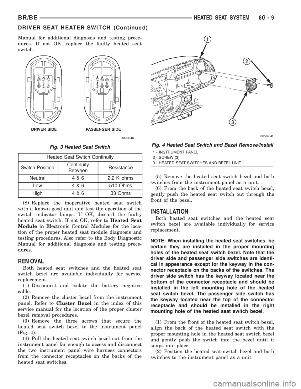
Heated Seat Switch Continuity
Switch PositionContinuity
BetweenResistance
Neutral 4 & 6 2.2 Kilohms
Low 4 & 6 510 Ohms
High 4 & 6 33 Ohms
(8) Replace the inoperative heated seat switch
with a known good unit and test the operation of the
switch indicator lamps. If OK, discard the faulty
heated seat switch. If not OK, refer toHeated Seat
Modulein Electronic Control Modules for the loca-
tion of the proper heated seat module diagnosis and
testing procedures. Also refer to the Body Diagnostic
Manual for additional diagnosis and testing proce-
dures.
REMOVAL
Both heated seat switches and the heated seat
switch bezel are available individually for service
replacement.
(1) Disconnect and isolate the battery negative
cable.
(2) Remove the cluster bezel from the instrument
panel. Refer toCluster Bezelin the index of this
service manual for the location of the proper cluster
bezel removal procedures.
(3) Remove the three screws that secure the
heated seat switch bezel to the instrument panel
(Fig. 4).
(4) Pull the heated seat switch bezel out from the
instrument panel far enough to access and disconnect
the two instrument panel wire harness connectors
from the connector receptacles on the backs of the
heated seat switches.(5) Remove the heated seat switch bezel and both
switches from the instrument panel as a unit.
(6) From the back of the heated seat switch bezel,
gently push the heated seat switch out through the
front of the bezel.
INSTALLATION
Both heated seat switches and the heated seat
switch bezel are available individually for service
replacement.
NOTE: When installing the heated seat switches, be
certain they are installed in the proper mounting
holes of the heated seat switch bezel. Note that the
driver side and passenger side switches are identi-
cal in appearance except for the keyway in the con-
nector receptacle on the backs of the switches. The
driver side switch has the keyway located near the
bottom of the connector receptacle and should be
installed in the left mounting hole of the heated
seat switch bezel. The passenger side switch has
the keyway located near the top of the connector
receptacle and should be installed in the right
mounting hole of the heated seat switch bezel.
(1) From the front of the heated seat switch bezel,
align the back of the heated seat switch with the
proper mounting hole in the heated seat switch bezel
and gently push the switch into the bezel until it
snaps into place.
(2) Position the heated seat switch bezel and both
switches to the instrument panel as a unit.
Fig. 3 Heated Seat SwitchFig. 4 Heated Seat Switch and Bezel Remove/Install
1 - INSTRUMENT PANEL
2 - SCREW (3)
3 - HEATED SEAT SWITCHES AND BEZEL UNIT
BR/BEHEATED SEAT SYSTEM 8G - 9
DRIVER SEAT HEATER SWITCH (Continued)
Page 525 of 2889

(3) Reconnect the two instrument panel wire har-
ness connectors to the connector receptacles on the
backs of the heated seat switches.
(4) Position the heated seat switch bezel and both
switches in the instrument panel mounting hole as a
unit.
(5) Install and tighten the three screws that secure
the heated seat switch bezel to the instrument panel.
Tighten the screws to 2.2 N´m (20 in. lbs.).
(6) Install the cluster bezel onto the instrument
panel. Refer toCluster Bezelin the index of this
service manual for the location of the proper cluster
bezel installation procedures.
(7) Reconnect the battery negative cable.
HEATED SEAT ELEMENT
DESCRIPTION
Vehicles equipped with the optional heated seat
system have two sets of electrically operated heating
element grids located in each outboard seating posi-
tion of the front seat, one set for the seat cushion
and the other set for the seat back. Each of the
heated seat element grids consists of a single length
of resistor wire that is routed in a zigzag pattern and
captured between the leather trim cover and the
foam rubber backing on the underside of its respec-
tive seat cushion trim cover and seat back trim cover
assembly. Short pigtail wires with connectors (Fig. 5)
are soldered to each end of each resistor wire ele-
ment grid, which connect all of the element grids foreach seating position to each other in series with the
heated seat module through the seat wire harness.
One temperature sensor is used for each outboard
seating position of the front seat, and it is located in
the center insert area of the seat cushion cover. The
heated seat sensors and their pigtail wires are also
captured between the leather trim cover and the
foam rubber backing on the underside of their
respective seat cushion trim cover assemblies. The
heated seat sensors are Negative Thermal Coefficient
(NTC) thermistors. The sensors for both front seats
receive a voltage feed from a single output of the
heated seat module, but the module receives individ-
ual sensor inputs from the driver side and passenger
side sensors.
The heated seat elements and sensors cannot be
repaired. If damaged or faulty, the front seat cushion
trim cover or front seat back trim cover assembly
must be replaced. Refer toFront Seat Cushion
Cover - Quad CaborFront Seat Back Cover -
Quad Cabin the index of this service manual for
the location of the proper front seat trim cover
removal and installation procedures.
OPERATION
One end of the heated seat element resistor wire is
connected to a ground feed at all times through a
splice in the heated seat module ground circuit. Bat-
tery current is directed to the other end of the heated
seat element resistor wire by the energized N-chan-
nel Field Effect Transistor (N-FET) located within
the heated seat module. The heated seat module will
energize the N-FET only when the heated seat
switch is in the Low or High position and the heated
seat sensor indicates that the seat cushion surface
temperature is below the selected (Low or High) tem-
perature set point. As electrical current passes
through the heating element grid, the resistance of
the wire used in the element disperses some of that
electrical current in the form of heat. The heat pro-
duced by the heated seat element grid then radiates
through the underside of the seat cushion and seat
back trim covers, warming the seat cover and its
occupant.
The resistance of the heated seat sensor increases
and decreases as the surface temperature of the seat
cushion cover changes. The heated seat module sup-
plies each sensor with a voltage feed, then detects
the sensor resistance by monitoring the voltage of the
separate sensor return circuits. The heated seat mod-
ule compares the heated seat sensor resistance (seat
cushion surface temperature) with the heated seat
switch resistance (Low or High set point) to deter-
mine when the heated seat element grids need to be
cycled on or off in order to maintain the selected tem-
perature set point.
Fig. 5 Heated Seat Cushion Trim Cover
1 - TO SEAT BACK COVER
2 - TO SEAT WIRE HARNESS
3 - FOAM PADDING
4 - HEATED SEAT CUSHION TRIM COVER
5 - TO ELEMENT GRIDS
6 - TO ELEMENT GRIDS AND SENSOR
8G - 10 HEATED SEAT SYSTEMBR/BE
DRIVER SEAT HEATER SWITCH (Continued)
Page 528 of 2889
(3) The relay normally open terminal (87) is con-
nected to the common feed terminal (30) in the ener-
gized position. This terminal supplies battery voltage
to the heated seat module. There should be continu-
ity between the cavity for relay terminal 87 and the
B(+) to heated seat module circuit cavity of the
heated seat module wire harness connector at all
times. If OK, go to Step 4. If not OK, repair the open
B(+) to heated seat module circuit to the heated seat
module as required.
(4) The coil battery terminal (86) is connected to
the electromagnet in the relay. It is connected to bat-
tery voltage and should be hot at all times. Check for
battery voltage at the cavity for relay terminal 86. If
OK, go to Step 5. If not OK, repair the open circuit to
the fused B(+) fuse in the PDC as required.
(5) The coil ground terminal (85) is connected to
the electromagnet in the relay. It is grounded by the
premium version of the Central Timer Module (CTM)
in response to an engine speed message received over
the Chrysler Collision Detection (CCD) data bus from
the Powertrain Control Module (PCM) when the
engine is running. Check for continuity between the
cavity for relay terminal 85 and the heated seat relay
control circuit cavity of the CTM wire harness con-
nector. There should be continuity at all times. If OK,
use a DRBIIItscan tool and the proper diagnostic
procedures manual to test the operation of the CTM
and CCD data bus. If not OK, repair the open heated
seat relay control circuit as required.
REMOVAL
(1) Disconnect and isolate the battery negative
cable.
(2) Remove the fuse access panel by inserting a
finger in the finger recess molded into the panel and
then pulling the panel sharply away from the left
outboard end of the instrument panel.
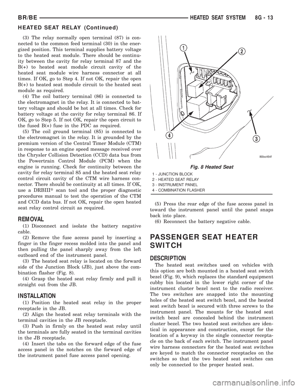
(3) The heated seat relay is located on the forward
side of the Junction Block (JB), just above the com-
bination flasher (Fig. 8).
(4) Grasp the heated seat relay firmly and pull it
straight out from the JB.
INSTALLATION
(1) Position the heated seat relay in the proper
receptacle in the JB.
(2) Align the heated seat relay terminals with the
terminal cavities in the JB receptacle.
(3) Push in firmly on the heated seat relay until
the terminals are fully seated in the terminal cavities
in the JB receptacle.
(4) Insert the tabs on the forward edge of the fuse
access panel in the notches on the forward edge of
the instrument panel fuse access panel opening.(5) Press the rear edge of the fuse access panel in
toward the instrument panel until the panel snaps
back into place.
(6) Reconnect the battery negative cable.
PASSENGER SEAT HEATER
SWITCH
DESCRIPTION
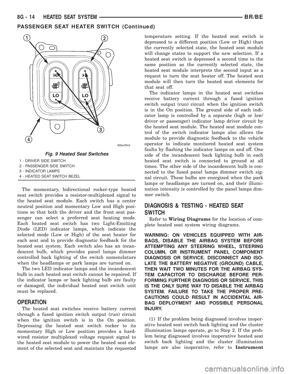
The heated seat switches used on vehicles with
this option are both mounted in a heated seat switch
bezel (Fig. 9), which replaces the standard equipment
cubby bin located in the lower right corner of the
instrument cluster bezel next to the radio receiver.
The two switches are snapped into the mounting
holes of the heated seat switch bezel, and the heated
seat switch bezel is secured with three screws to the
instrument panel. The mounts for the heated seat
switch bezel are concealed behind the instrument
cluster bezel. The two heated seat switches are iden-
tical in appearance and construction, except for the
location of a keyway in the single connector recepta-
cle on the back of each switch. The instrument panel
wire harness connectors for the heated seat switches
are keyed to match the connector receptacles on the
switches so that the two heated seat switches can
only be connected to the proper heated seat.
Fig. 8 Heated Seat
1 - JUNCTION BLOCK
2 - HEATED SEAT RELAY
3 - INSTRUMENT PANEL
4 - COMBINATION FLASHER
BR/BEHEATED SEAT SYSTEM 8G - 13
HEATED SEAT RELAY (Continued)
Page 529 of 2889
The momentary, bidirectional rocker-type heated
seat switch provides a resistor-multiplexed signal to
the heated seat module. Each switch has a center
neutral position and momentary Low and High posi-
tions so that both the driver and the front seat pas-
senger can select a preferred seat heating mode.
Each heated seat switch has two Light-Emitting
Diode (LED) indicator lamps, which indicate the
selected mode (Low or High) of the seat heater for
each seat and to provide diagnostic feedback for the
heated seat system. Each switch also has an incan-
descent bulb, which provides panel lamps dimmer
controlled back lighting of the switch nomenclature
when the headlamps or park lamps are turned on.
The two LED indicator lamps and the incandescent
bulb in each heated seat switch cannot be repaired. If
the indicator lamps or back lighting bulb are faulty
or damaged, the individual heated seat switch unit
must be replaced.
OPERATION
The heated seat switches receive battery current
through a fused ignition switch output (run) circuit
when the ignition switch is in the On position.
Depressing the heated seat switch rocker to its
momentary High or Low position provides a hard-
wired resistor multiplexed voltage request signal to
the heated seat module to power the heated seat ele-
ment of the selected seat and maintain the requestedtemperature setting. If the heated seat switch is
depressed to a different position (Low or High) than
the currently selected state, the heated seat module
will change states to support the new selection. If a
heated seat switch is depressed a second time to the
same position as the currently selected state, the
heated seat module interprets the second input as a
request to turn the seat heater off. The heated seat
module will then turn the heated seat elements for
that seat off.
The indicator lamps in the heated seat switches
receive battery current through a fused ignition
switch output (run) circuit when the ignition switch
is in the On position. The ground side of each indi-
cator lamp is controlled by a separate (high or low/
driver or passenger) indicator lamp driver circuit by
the heated seat module. The heated seat module con-
trol of the switch indicator lamps also allows the
module to provide diagnostic feedback to the vehicle
operator to indicate monitored heated seat system
faults by flashing the indicator lamps on and off. One
side of the incandescent back lighting bulb in each
heated seat switch is connected to ground at all
times. The other side of the incandescent bulb is con-
nected to the fused panel lamps dimmer switch sig-
nal circuit. These bulbs are energized when the park
lamps or headlamps are turned on, and their illumi-
nation intensity is controlled by the panel lamps dim-
mer switch.
DIAGNOSIS & TESTING - HEATED SEAT
SWITCH
Refer toWiring Diagramsfor the location of com-
plete heated seat system wiring diagrams.
WARNING: ON VEHICLES EQUIPPED WITH AIR-
BAGS, DISABLE THE AIRBAG SYSTEM BEFORE
ATTEMPTING ANY STEERING WHEEL, STEERING
COLUMN, OR INSTRUMENT PANEL COMPONENT
DIAGNOSIS OR SERVICE. DISCONNECT AND ISO-
LATE THE BATTERY NEGATIVE (GROUND) CABLE,
THEN WAIT TWO MINUTES FOR THE AIRBAG SYS-
TEM CAPACITOR TO DISCHARGE BEFORE PER-
FORMING FURTHER DIAGNOSIS OR SERVICE. THIS
IS THE ONLY SURE WAY TO DISABLE THE AIRBAG
SYSTEM. FAILURE TO TAKE THE PROPER PRE-
CAUTIONS COULD RESULT IN ACCIDENTAL AIR-
BAG DEPLOYMENT AND POSSIBLE PERSONAL
INJURY.
(1) If the problem being diagnosed involves inoper-
ative heated seat switch back lighting and the cluster
illumination lamps operate, go to Step 2. If the prob-
lem being diagnosed involves inoperative heated seat
switch back lighting and the cluster illumination
lamps are also inoperative, refer toInstrument
Fig. 9 Heated Seat Switches
1 - DRIVER SIDE SWITCH
2 - PASSENGER SIDE SWITCH
3 - INDICATOR LAMPS
4 - HEATED SEAT SWITCH BEZEL
8G - 14 HEATED SEAT SYSTEMBR/BE
PASSENGER SEAT HEATER SWITCH (Continued)
Page 530 of 2889
Clusterin the index of this service manual for the
proper cluster illumination lamps diagnosis and test-
ing procedures. If the problem being diagnosed
involves inoperative heated seat switch indicator
lamps and the heated seat elements do not heat,
refer to Step 4. If the problem being diagnosed
involves inoperative heated seat switch indicator
lamps and the heated seat elements do heat, go to
Step 8. If the problem being diagnosed involves a
heated seat switch indicator lamp that remains illu-
minated after the heated seat has been turned Off,
refer toHeated Seat Modulein Electronic Control
Modules for the location of the proper heated seat
module diagnosis and testing procedures. Also refer
to the Body Diagnostic Manual for additional diagno-
sis and testing procedures.
(2) Disconnect and isolate the battery negative
cable. Remove the heated seat switch and bezel unit
from the instrument panel. Disconnect the instru-
ment panel wire harness connector from the connec-
tor receptacle on the back of the heated seat switch
to be tested. Check for continuity between the ground
circuit cavity of the instrument panel wire harness
connector for the heated seat switch and a good
ground. There should be continuity. If OK, go to Step
3. If not OK, repair the open ground circuit to ground
as required.
(3) Reconnect the battery negative cable. Turn the
park lamps on with the headlamp switch. Rotate the
panel lamps dimmer thumbwheel on the headlamp
switch upward to just before the interior lamps
detent. Check for battery voltage at the fused panel
lamps dimmer switch signal circuit cavity of the
instrument panel wire harness connector for the
heated seat switch. If OK, replace the faulty heated
seat switch. If not OK, repair the open fused panel
lamps dimmer switch signal circuit to the fuse in the
Junction Block (JB) as required.
(4) Check the fused ignition switch output (run)
fuse in the Junction Block (JB). If OK, go to Step 5.
If not OK, repair the shorted circuit or component as
required and replace the faulty fuse.
(5) Turn the ignition switch to the On position.
Check for battery voltage at the fused ignition switch
output (run) fuse in the JB. If OK, go to Step 6. If
not OK, repair the open fused ignition switch output
(run) circuit to the ignition switch as required.
(6) Disconnect and isolate the battery negative
cable. Remove the heated seat switch and bezel unit
from the instrument panel. Disconnect the instru-
ment panel wire harness connector from the connec-
tor receptacle on the back of the heated seat switch
to be tested. Reconnect the battery negative cable.
Turn the ignition switch to the On position. Check
for battery voltage at the fused ignition switch out-
put (run) circuit cavity of the instrument panel wireharness connector for the heated seat switch. If OK,
go to Step 7. If not OK, repair the open fused ignition
switch output (run) circuit to the JB fuse as required.
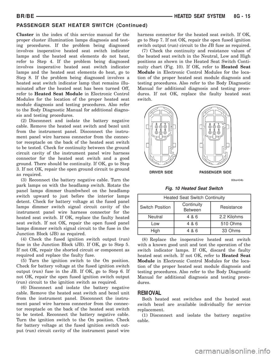
(7) Check the continuity and resistance values of
the heated seat switch in the Neutral, Low and High
positions as shown in the Heated Seat Switch Conti-
nuity chart (Fig. 10). If OK, refer toHeated Seat
Modulein Electronic Control Modules for the loca-
tion of the proper heated seat module diagnosis and
testing procedures. Also refer to the Body Diagnostic
Manual for additional diagnosis and testing proce-
dures. If not OK, replace the faulty heated seat
switch.
Heated Seat Switch Continuity
Switch PositionContinuity
BetweenResistance
Neutral 4 & 6 2.2 Kilohms
Low 4 & 6 510 Ohms
High 4 & 6 33 Ohms
(8) Replace the inoperative heated seat switch
with a known good unit and test the operation of the
switch indicator lamps. If OK, discard the faulty
heated seat switch. If not OK, refer toHeated Seat
Modulein Electronic Control Modules for the loca-
tion of the proper heated seat module diagnosis and
testing procedures. Also refer to the Body Diagnostic
Manual for additional diagnosis and testing proce-
dures.
REMOVAL
Both heated seat switches and the heated seat
switch bezel are available individually for service
replacement.
(1) Disconnect and isolate the battery negative
cable.
Fig. 10 Heated Seat Switch
BR/BEHEATED SEAT SYSTEM 8G - 15
PASSENGER SEAT HEATER SWITCH (Continued)
Page 531 of 2889
(2) Remove the cluster bezel from the instrument
panel. Refer toCluster Bezelin the index of this
service manual for the location of the proper cluster
bezel removal procedures.
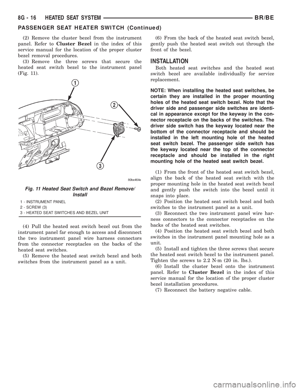
(3) Remove the three screws that secure the
heated seat switch bezel to the instrument panel
(Fig. 11).
(4) Pull the heated seat switch bezel out from the
instrument panel far enough to access and disconnect
the two instrument panel wire harness connectors
from the connector receptacles on the backs of the
heated seat switches.
(5) Remove the heated seat switch bezel and both
switches from the instrument panel as a unit.(6) From the back of the heated seat switch bezel,
gently push the heated seat switch out through the
front of the bezel.
INSTALLATION
Both heated seat switches and the heated seat
switch bezel are available individually for service
replacement.
NOTE: When installing the heated seat switches, be
certain they are installed in the proper mounting
holes of the heated seat switch bezel. Note that the
driver side and passenger side switches are identi-
cal in appearance except for the keyway in the con-
nector receptacle on the backs of the switches. The
driver side switch has the keyway located near the
bottom of the connector receptacle and should be
installed in the left mounting hole of the heated
seat switch bezel. The passenger side switch has
the keyway located near the top of the connector
receptacle and should be installed in the right
mounting hole of the heated seat switch bezel.
(1) From the front of the heated seat switch bezel,
align the back of the heated seat switch with the
proper mounting hole in the heated seat switch bezel
and gently push the switch into the bezel until it
snaps into place.
(2) Position the heated seat switch bezel and both
switches to the instrument panel as a unit.
(3) Reconnect the two instrument panel wire har-
ness connectors to the connector receptacles on the
backs of the heated seat switches.
(4) Position the heated seat switch bezel and both
switches in the instrument panel mounting hole as a
unit.
(5) Install and tighten the three screws that secure
the heated seat switch bezel to the instrument panel.
Tighten the screws to 2.2 N´m (20 in. lbs.).
(6) Install the cluster bezel onto the instrument
panel. Refer toCluster Bezelin the index of this
service manual for the location of the proper cluster
bezel installation procedures.
(7) Reconnect the battery negative cable.
Fig. 11 Heated Seat Switch and Bezel Remove/
Install
1 - INSTRUMENT PANEL
2 - SCREW (3)
3 - HEATED SEAT SWITCHES AND BEZEL UNIT
8G - 16 HEATED SEAT SYSTEMBR/BE
PASSENGER SEAT HEATER SWITCH (Continued)
Page 540 of 2889

SPARK PLUG CABLE RESISTANCE
MINIMUM MAXIMUM
250 Ohms Per Inch 1000 Ohms Per Inch
3000 Ohms Per Foot 12,000 Ohms Per Foot
SPARK PLUGS
ENGINE PLUG TYPE ELECTRODE GAP
3.9L V-6 RC12LC4 1.01 mm (.040 in.)
5.2L/5.9L V-8 RC12LC4 1.01 mm (.040 in.)
8.0L V-10 QC9MC4 1.14 mm (.045 in.)
IGNITION COIL RESISTANCEÐ3.9L/5.2L/5.9L ENGINES
COIL MANUFACTURERPRIMARY RESISTANCE
21-27ÉC (70-80ÉF)SECONDARY RESISTANCE 21-27ÉC
(70-80ÉF)
Diamond 0.97 - 1.18 Ohms 11,300 - 15,300 Ohms
Toyodenso 0.95 - 1.20 Ohms 11,300 - 13,300 Ohms
IGNITION COIL RESISTANCEÐ8.0L V-10
ENGINE
Primary Resistance: 0.53-0.65 Ohms. Test across the
primary connector. Refer to text for test procedures.
Secondary Resistance: 10.9-14.7K Ohms. Test
across the individual coil towers. Refer to text for test
procedures.
IGNITION TIMING
Ignition timing is not adjustable on any engine.
AUTOMATIC SHUT DOWN
RELAY
DESCRIPTION - PCM OUTPUT
The 5±pin, 12±volt, Automatic Shutdown (ASD)
relay is located in the Power Distribution Center
(PDC). Refer to label on PDC cover for relay location.
OPERATION - PCM OUTPUT
The ASD relay supplies battery voltage (12+ volts)
to the fuel injectors and ignition coil(s). With certain
emissions packages it also supplies 12±volts to the
oxygen sensor heating elements.
The ground circuit for the coil within the ASD
relay is controlled by the Powertrain Control Module
(PCM). The PCM operates the ASD relay by switch-
ing its ground circuit on and off.The ASD relay will be shut±down, meaning the
12±volt power supply to the ASD relay will be de-ac-
tivated by the PCM if:
²the ignition key is left in the ON position. This
is if the engine has not been running for approxi-
mately 1.8 seconds.
²there is a crankshaft position sensor signal to
the PCM that is lower than pre-determined values.
OPERATION - ASD SENSE - PCM INPUT
A 12 volt signal at this input indicates to the PCM
that the ASD has been activated. The relay is used to
connect the oxygen sensor heater element, ignition
coil and fuel injectors to 12 volt + power supply.
This input is used only to sense that the ASD relay
is energized. If the Powertrain Control Module
(PCM) does not see 12 volts at this input when the
ASD should be activated, it will set a Diagnostic
Trouble Code (DTC).
DIAGNOSIS AND TESTING - ASD AND FUEL
PUMP RELAYS
The following description of operation and
tests apply only to the Automatic Shutdown
(ASD) and fuel pump relays. The terminals on the
bottom of each relay are numbered. Two different
types of relays may be used, (Fig. 1) or (Fig. 2).
²Terminal number 30 is connected to battery volt-
age. For both the ASD and fuel pump relays, termi-
nal 30 is connected to battery voltage at all times.
BR/BEIGNITION CONTROL 8I - 3
IGNITION CONTROL (Continued)
Page 593 of 2889
above the temperature gauge. The voltage gauge con-
sists of a movable gauge needle or pointer controlled
by the instrument cluster circuitry and a fixed 90
degree scale on the cluster overlay that reads left-to-
right from 8 volts to 18 volts. An International Con-
trol and Display Symbol icon for ªBattery Charging
Conditionº is located directly below the lowest grad-
uation of the gauge scale. The voltage gauge graphics
are white against a black field except for a single red
graduation at each end of the gauge scale, making
them clearly visible within the instrument cluster in
daylight. When illuminated from behind by the panel
lamps dimmer controlled cluster illumination lighting
with the exterior lamps turned On, the white graph-
ics appear blue-green and the red graphics appear
red. The orange gauge needle is internally illumi-
nated. Gauge illumination is provided by replaceable
incandescent bulb and bulb holder units located on
the instrument cluster electronic circuit board. The
voltage gauge is serviced as a unit with the instru-
ment cluster.
OPERATION
The voltage gauge gives an indication to the vehi-
cle operator of the electrical system voltage. This
gauge is controlled by the instrument cluster circuit
board based upon the cluster programming and elec-
tronic messages received by the cluster from the
Powertrain Control Module (PCM) over the Chrysler
Collision Detection (CCD) data bus. The voltage
gauge is an air core magnetic unit that receives bat-
tery current on the instrument cluster electronic cir-
cuit board through the fused ignition switch output
(st-run) circuit whenever the ignition switch is in the
On or Start positions. The cluster is programmed to
move the gauge needle back to the low end of the
scale after the ignition switch is turned to the Off
position. The instrument cluster circuitry controls
the gauge needle position and provides the following
features:
²Charge Fail Message- Each time the cluster
receives a message from the PCM indicating a charge
fail condition (system voltage is 10.8 volts or lower),
the gauge needle is moved to the 8 volt graduation
on the gauge scale and the check gauges indicator is
illuminated. The gauge needle remains on the 8 volt
graduation and the check gauges indicator remains
illuminated until the cluster receives a message from
the PCM indicating there is no charge fail condition
(system voltage is 10.9 volts or higher, but lower
than 16.7 volts), or until the ignition switch is turned
to the Off position, whichever occurs first. On models
equipped with the optional diesel engine, the instru-
ment cluster is programmed to support the voltmeter
gauge needle above the low end of normal graduation
and suppress the check gauges indicator operationuntil ten seconds after the engine intake manifold air
heater has completed its cycle.
²Voltage High Message- Each time the cluster
receives a message from the PCM indicating a volt-
age high condition (system voltage is 16.7 volts or
higher), the gauge needle is moved to the 18 volt
graduation on the gauge scale and the check gauges
indicator is illuminated. The gauge needle remains
on the 18 volt graduation and the check gauges indi-
cator remains illuminated until the cluster receives a
message from the PCM indicating there is no voltage
high condition (system voltage is 16.6 volts or lower,
but higher than 10.9 volts), or until the ignition
switch is turned to the Off position, whichever occurs
first.
²Message Failure- If the cluster fails to receive
a system voltage message, it will hold the gauge nee-
dle at the last indication until a new message is
received, or until the ignition switch is turned to the
Off position, whichever occurs first.
²Actuator Test- Each time the cluster is put
through the actuator test, the gauge needle will be
swept to several calibration points on the gauge scale
in a prescribed sequence in order to confirm the func-
tionality of the gauge and the cluster control cir-
cuitry.
The PCM continually monitors the system voltage
to control the generator output. The PCM then sends
the proper system voltage messages to the instru-
ment cluster. For further diagnosis of the voltage
gauge or the instrument cluster circuitry that con-
trols the gauge, (Refer to 8 - ELECTRICAL/INSTRU-
MENT CLUSTER - DIAGNOSIS AND TESTING). If
the instrument cluster turns on the check gauges
indicator due to a charge fail or voltage high condi-
tion, it may indicate that the charging system
requires service. For proper diagnosis of the charging
system, the CCD data bus, or the message inputs to
the instrument cluster that control the voltage
gauge, a DRBIIItscan tool is required. Refer to the
appropriate diagnostic information.
WAIT-TO-START INDICATOR
DESCRIPTION
A wait-to-start indicator is standard equipment on
all instrument clusters, but is only functional in vehi-
cles equipped with an optional diesel engine. The
wait-to-start indicator is located near the lower edge
of the instrument cluster overlay, to the right of cen-
ter. The wait-to-start indicator consists of a stenciled
cutout of the text ªWAIT TO STARTº in the opaque
layer of the cluster overlay. The dark outer layer of
the overlay prevents the indicator from being clearly
visible when it is not illuminated. A red lens located
8J - 34 INSTRUMENT CLUSTERBR/BE
VOLTAGE GAUGE (Continued)