2001 DODGE RAM wheel
[x] Cancel search: wheelPage 2762 of 2889
DIAGNOSIS AND TESTING - BLOWER MOTOR
WARNING: ON VEHICLES EQUIPPED WITH AIRBAGS,
DISABLE THE AIRBAG SYSTEM BEFORE ATTEMPT-
ING ANY STEERING WHEEL, STEERING COLUMN, OR
INSTRUMENT PANEL COMPONENT DIAGNOSIS OR
SERVICE. DISCONNECT AND ISOLATE THE BATTERY
NEGATIVE (GROUND) CABLE, THEN WAIT TWO MIN-
UTES FOR THE AIRBAG SYSTEM CAPACITOR TO DIS-
CHARGE BEFORE PERFORMING FURTHER
DIAGNOSIS OR SERVICE. THIS IS THE ONLY SURE
WAY TO DISABLE THE AIRBAG SYSTEM. FAILURE TO
TAKE THE PROPER PRECAUTIONS COULD RESULT
IN AN ACCIDENTAL AIRBAG DEPLOYMENT AND POS-
SIBLE PERSONAL INJURY.
For circuit descriptions and diagrams, (Refer to
Appropriate Wiring Information). Possible causes of
an inoperative blower motor include:
²Faulty fuse
²Faulty blower motor circuit wiring or wire har-
ness connectors
²Faulty blower motor resistor
²Faulty blower motor relay
²Faulty blower motor switch
²Faulty a/c heater mode control switch
²Faulty blower motor.
Possible causes of the blower motor not operating
in all speeds include:
²Faulty fuse
²Faulty blower motor switch
²Faulty blower motor resistor
²Faulty blower motor relay
²Faulty blower motor circuit wiring or wire har-
ness connectors.
VIBRATION
Possible causes of blower motor vibration include:
²Improper blower motor mounting
²Improper blower wheel mounting
²Blower wheel out of balance or deformed
²Blower motor faulty.
NOISE
To verify that the blower is the source of the noise,
unplug the blower motor wire harness connector and
operate the HVAC system. If the noise goes away,
possible causes include:
²Foreign material in the HVAC housing
²Improper blower motor mounting
²Improper blower wheel mounting
²Blower motor faulty.
REMOVAL
(1) Disconnect and isolate the battery negative
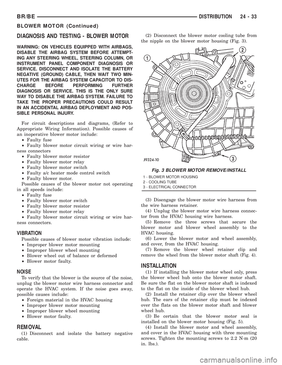
cable.(2) Disconnect the blower motor cooling tube from
the nipple on the blower motor housing (Fig. 3).
(3) Disengage the blower motor wire harness from
the wire harness retainer.
(4) Unplug the blower motor wire harness connec-
tor from the HVAC housing wire harness.
(5) Remove the three screws that secure the
blower motor and blower wheel assembly to the
HVAC housing.
(6) Lower the blower motor and wheel assembly,
and cover, from the HVAC housing.
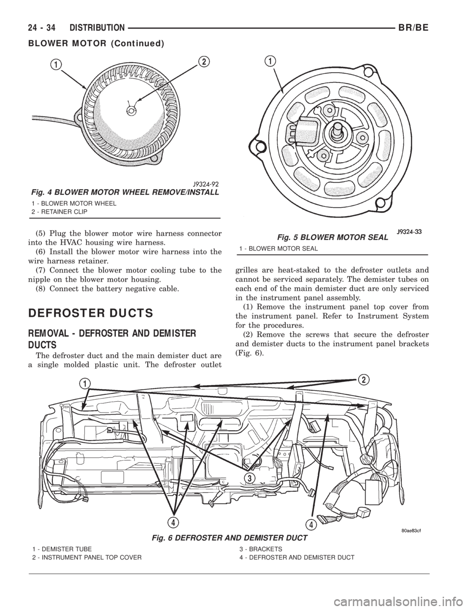
(7)
Remove the blower wheel retainer clip and
remove the wheel from the blower motor shaft (Fig. 4).
INSTALLATION
(1) If installing the blower motor wheel only, press
the blower wheel hub onto the blower motor shaft.
Be sure the flat on the blower motor shaft is indexed
to the flat on the inside of the blower wheel hub.
(2) Install the retainer clip over the blower wheel
hub. The ears of the retainer clip must be indexed
over the flats on the blower motor shaft and blower
wheel hub.
(3) Be certain that the blower motor seal is
installed on the blower motor housing (Fig. 5).
(4) Install the blower motor and wheel assembly,
and cover in the HVAC housing with three mounting
screws. Tighten the mounting screws to 2.2 N´m (20
in. lbs.).
Fig. 3 BLOWER MOTOR REMOVE/INSTALL
1 - BLOWER MOTOR HOUSING
2 - COOLING TUBE
3 - ELECTRICAL CONNECTOR
BR/BEDISTRIBUTION 24 - 33
BLOWER MOTOR (Continued)
Page 2763 of 2889
(5) Plug the blower motor wire harness connector
into the HVAC housing wire harness.
(6) Install the blower motor wire harness into the
wire harness retainer.
(7) Connect the blower motor cooling tube to the
nipple on the blower motor housing.
(8) Connect the battery negative cable.
DEFROSTER DUCTS
REMOVAL - DEFROSTER AND DEMISTER
DUCTS
The defroster duct and the main demister duct are
a single molded plastic unit. The defroster outletgrilles are heat-staked to the defroster outlets and
cannot be serviced separately. The demister tubes on
each end of the main demister duct are only serviced
in the instrument panel assembly.
(1) Remove the instrument panel top cover from
the instrument panel. Refer to Instrument System
for the procedures.
(2) Remove the screws that secure the defroster
and demister ducts to the instrument panel brackets
(Fig. 6).
Fig. 5 BLOWER MOTOR SEAL
1 - BLOWER MOTOR SEAL
Fig. 6 DEFROSTER AND DEMISTER DUCT
1 - DEMISTER TUBE
2 - INSTRUMENT PANEL TOP COVER3 - BRACKETS
4 - DEFROSTER AND DEMISTER DUCT
Fig. 4 BLOWER MOTOR WHEEL REMOVE/INSTALL
1 - BLOWER MOTOR WHEEL
2 - RETAINER CLIP
24 - 34 DISTRIBUTIONBR/BE
BLOWER MOTOR (Continued)
Page 2764 of 2889
(3) Disengage the demister tubes from each end of
the main demister duct.
(4) Remove the defroster and demister duct unit
from the instrument panel.
REMOVAL - DEFROSTER AND DEMISTER
DUCT ADAPTER
(1) Roll the instrument panel assembly down, but
do not remove it from the vehicle. Refer to Instru-
ment Panel System for the procedures.
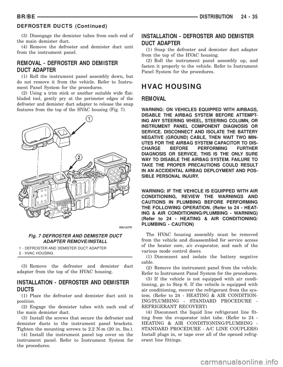
(2)
Using a trim stick or another suitable wide flat-
bladed tool, gently pry at the perimeter edges of the
defroster and demister duct adapter to release the snap
features from the top of the HVAC housing (Fig. 7).
(3) Remove the defroster and demister duct
adapter from the top of the HVAC housing.
INSTALLATION - DEFROSTER AND DEMISTER
DUCTS
(1) Place the defroster and demister duct unit in
position.
(2) Engage the demister tubes with each end of
the main demister duct.
(3) Install the screws that secure the defroster and
demister ducts to the instrument panel brackets.
Tighten the mounting screws to 2.2 N´m (20 in. lbs.).
(4) Install the instrument panel top cover on the
instrument panel. Refer to Instrument System for
the procedures.
INSTALLATION - DEFROSTER AND DEMISTER
DUCT ADAPTER
(1) Snap the defroster and demister duct adapter
from the top of the HVAC housing.
(2) Roll the instrument panel assembly up, and
fasten it properly to the vehicle. Refer to Instrument
Panel System for the procedures.
HVAC HOUSING
REMOVAL
WARNING: ON VEHICLES EQUIPPED WITH AIRBAGS,
DISABLE THE AIRBAG SYSTEM BEFORE ATTEMPT-
ING ANY STEERING WHEEL, STEERING COLUMN, OR
INSTRUMENT PANEL COMPONENT DIAGNOSIS OR
SERVICE. DISCONNECT AND ISOLATE THE BATTERY
NEGATIVE (GROUND) CABLE, THEN WAIT TWO MIN-
UTES FOR THE AIRBAG SYSTEM CAPACITOR TO DIS-
CHARGE BEFORE PERFORMING FURTHER
DIAGNOSIS OR SERVICE. THIS IS THE ONLY SURE
WAY TO DISABLE THE AIRBAG SYSTEM. FAILURE TO
TAKE THE PROPER PRECAUTIONS COULD RESULT
IN AN ACCIDENTAL AIRBAG DEPLOYMENT AND POS-
SIBLE PERSONAL INJURY.
WARNING: IF THE VEHICLE IS EQUIPPED WITH AIR
CONDITIONING, REVIEW THE WARNINGS AND
CAUTIONS IN PLUMBING BEFORE PERFORMING
THE FOLLOWING OPERATION. (Refer to 24 - HEAT-
ING & AIR CONDITIONING/PLUMBING - WARNING)
(Refer to 24 - HEATING & AIR CONDITIONING/
PLUMBING - CAUTION)
The HVAC housing assembly must be removed
from the vehicle and disassembled for service access
of the heater core, a/c evaporator, and each of the
various mode control doors.
(1) Disconnect and isolate the battery negative
cable.
(2) Remove the instrument panel from the vehicle.
Refer to Instrument Panel System for the procedures.
(3) If the vehicle is not equipped with air condi-
tioning, go to Step 6. If the vehicle is equipped with
air conditioning, recover the refrigerant from the sys-
tem. (Refer to 24 - HEATING & AIR CONDITION-
ING/PLUMBING - STANDARD PROCEDURE -
REFRIGERANT RECOVERY)
(4) Disconnect the liquid line refrigerant line fit-
ting from the evaporator inlet tube. (Refer to 24 -
HEATING & AIR CONDITIONING/PLUMBING -
STANDARD PROCEDURE - A/C LINE COUPLERS)
Install plugs in, or tape over all of the opened refrig-
erant line fittings.
Fig. 7 DEFROSTER AND DEMISTER DUCT
ADAPTER REMOVE/INSTALL
1 - DEFROSTER AND DEMISTER DUCT ADAPTER
2 - HVAC HOUSING
BR/BEDISTRIBUTION 24 - 35
DEFROSTER DUCTS (Continued)
Page 2767 of 2889
BLEND DOOR
REMOVAL
(1) Remove the HVAC housing from the vehicle,
and disassemble the housing halves. (Refer to 24 -
HEATING & AIR CONDITIONING/DISTRIBUTION/
HVAC HOUSING - REMOVAL) (Refer to 24 - HEAT-
ING & AIR CONDITIONING/DISTRIBUTION/HVAC
HOUSING - DISASSEMBLY)
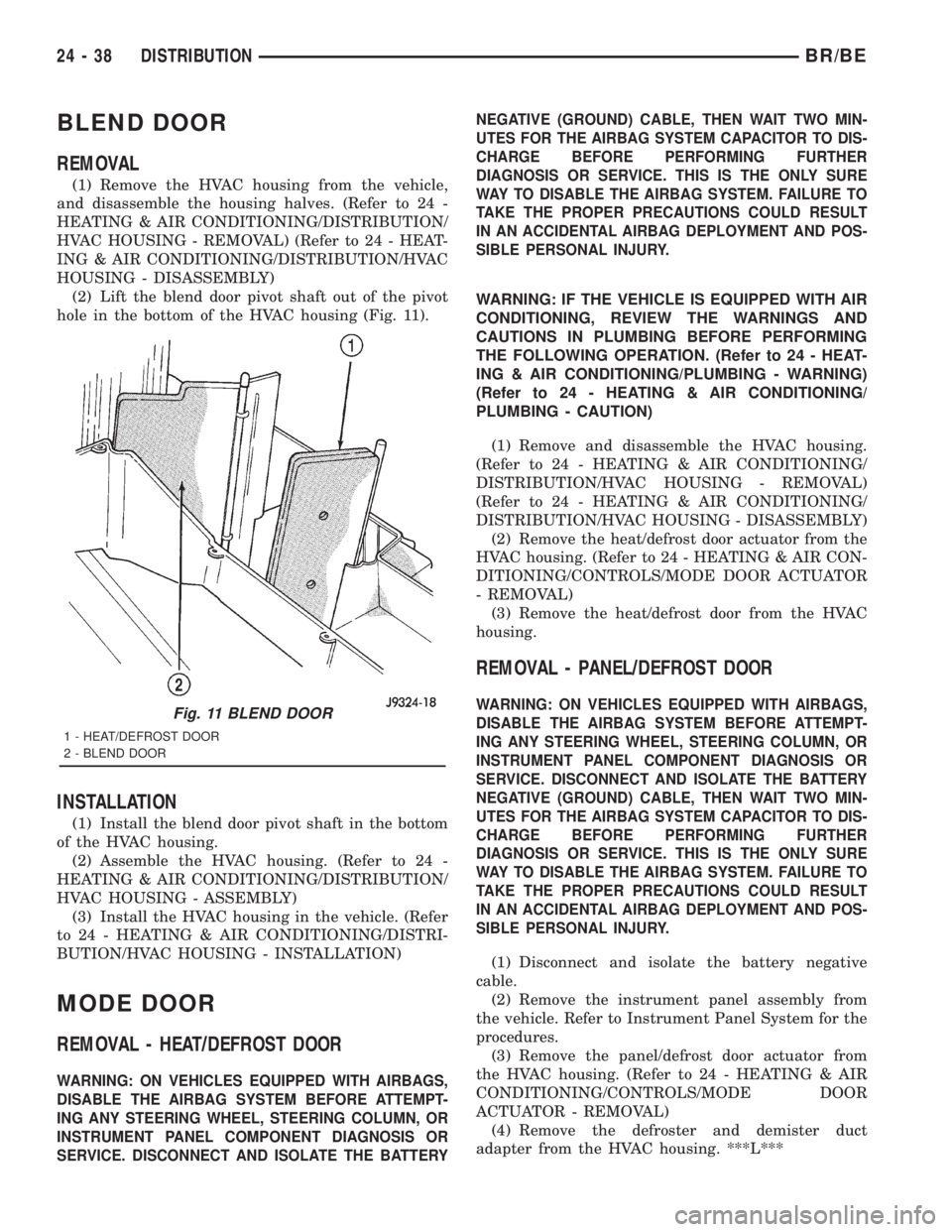
(2) Lift the blend door pivot shaft out of the pivot
hole in the bottom of the HVAC housing (Fig. 11).
INSTALLATION
(1) Install the blend door pivot shaft in the bottom
of the HVAC housing.
(2) Assemble the HVAC housing. (Refer to 24 -
HEATING & AIR CONDITIONING/DISTRIBUTION/
HVAC HOUSING - ASSEMBLY)
(3) Install the HVAC housing in the vehicle. (Refer
to 24 - HEATING & AIR CONDITIONING/DISTRI-
BUTION/HVAC HOUSING - INSTALLATION)
MODE DOOR
REMOVAL - HEAT/DEFROST DOOR
WARNING: ON VEHICLES EQUIPPED WITH AIRBAGS,
DISABLE THE AIRBAG SYSTEM BEFORE ATTEMPT-
ING ANY STEERING WHEEL, STEERING COLUMN, OR
INSTRUMENT PANEL COMPONENT DIAGNOSIS OR
SERVICE. DISCONNECT AND ISOLATE THE BATTERYNEGATIVE (GROUND) CABLE, THEN WAIT TWO MIN-
UTES FOR THE AIRBAG SYSTEM CAPACITOR TO DIS-
CHARGE BEFORE PERFORMING FURTHER
DIAGNOSIS OR SERVICE. THIS IS THE ONLY SURE
WAY TO DISABLE THE AIRBAG SYSTEM. FAILURE TO
TAKE THE PROPER PRECAUTIONS COULD RESULT
IN AN ACCIDENTAL AIRBAG DEPLOYMENT AND POS-
SIBLE PERSONAL INJURY.
WARNING: IF THE VEHICLE IS EQUIPPED WITH AIR
CONDITIONING, REVIEW THE WARNINGS AND
CAUTIONS IN PLUMBING BEFORE PERFORMING
THE FOLLOWING OPERATION. (Refer to 24 - HEAT-
ING & AIR CONDITIONING/PLUMBING - WARNING)
(Refer to 24 - HEATING & AIR CONDITIONING/
PLUMBING - CAUTION)
(1) Remove and disassemble the HVAC housing.
(Refer to 24 - HEATING & AIR CONDITIONING/
DISTRIBUTION/HVAC HOUSING - REMOVAL)
(Refer to 24 - HEATING & AIR CONDITIONING/
DISTRIBUTION/HVAC HOUSING - DISASSEMBLY)
(2) Remove the heat/defrost door actuator from the
HVAC housing. (Refer to 24 - HEATING & AIR CON-
DITIONING/CONTROLS/MODE DOOR ACTUATOR
- REMOVAL)
(3) Remove the heat/defrost door from the HVAC
housing.
REMOVAL - PANEL/DEFROST DOOR
WARNING: ON VEHICLES EQUIPPED WITH AIRBAGS,
DISABLE THE AIRBAG SYSTEM BEFORE ATTEMPT-
ING ANY STEERING WHEEL, STEERING COLUMN, OR
INSTRUMENT PANEL COMPONENT DIAGNOSIS OR
SERVICE. DISCONNECT AND ISOLATE THE BATTERY
NEGATIVE (GROUND) CABLE, THEN WAIT TWO MIN-
UTES FOR THE AIRBAG SYSTEM CAPACITOR TO DIS-
CHARGE BEFORE PERFORMING FURTHER
DIAGNOSIS OR SERVICE. THIS IS THE ONLY SURE
WAY TO DISABLE THE AIRBAG SYSTEM. FAILURE TO
TAKE THE PROPER PRECAUTIONS COULD RESULT
IN AN ACCIDENTAL AIRBAG DEPLOYMENT AND POS-
SIBLE PERSONAL INJURY.
(1) Disconnect and isolate the battery negative
cable.
(2) Remove the instrument panel assembly from
the vehicle. Refer to Instrument Panel System for the
procedures.
(3) Remove the panel/defrost door actuator from
the HVAC housing. (Refer to 24 - HEATING & AIR
CONDITIONING/CONTROLS/MODE DOOR
ACTUATOR - REMOVAL)
(4) Remove the defroster and demister duct
adapter from the HVAC housing. ***L***
Fig. 11 BLEND DOOR
1 - HEAT/DEFROST DOOR
2 - BLEND DOOR
24 - 38 DISTRIBUTIONBR/BE
Page 2768 of 2889
(5) Lift the panel/defrost door out of the top open-
ing of the HVAC housing.
INSTALLATION - HEAT/DEFROST DOOR
(1) Install the heat/defrost door in the HVAC hous-
ing.
(2) Assemble the HVAC housing. (Refer to 24 -
HEATING & AIR CONDITIONING/DISTRIBUTION/
HVAC HOUSING - ASSEMBLY)
(3) Install the heat/defrost door actuator on the
HVAC housing. (Refer to 24 - HEATING & AIR CON-
DITIONING/CONTROLS/MODE DOOR ACTUATOR
- INSTALLATION)
(4) Install the HVAC housing in the vehicle. (Refer
to 24 - HEATING & AIR CONDITIONING/DISTRI-
BUTION/HVAC HOUSING - INSTALLATION)
INSTALLATION - PANEL/DEFROST DOOR
(1) Install the panel/defrost door through the top
opening of the HVAC housing.
(2) Install the defroster and demister duct adapter
on the HVAC housing. (Refer to 24 - HEATING &
AIR CONDITIONING/DISTRIBUTION/DEFROSTER
DUCTS - INSTALLATION)
(3) Install the panel/defrost door actuator on the
HVAC housing. (Refer to 24 - HEATING & AIR CON-
DITIONING/CONTROLS/MODE DOOR ACTUATOR
- REMOVAL)
(4) Install the instrument panel assembly in the
vehicle. Refer to Instrument Panel System for the
procedures.
(5) Connect the battery negative cable.
RECIRCULATION DOOR
REMOVAL
WARNING: ON VEHICLES EQUIPPED WITH AIR-
BAGS, DISABLE THE AIRBAG SYSTEM BEFORE
ATTEMPTING ANY STEERING WHEEL, STEERING
COLUMN, OR INSTRUMENT PANEL COMPONENT
DIAGNOSIS OR SERVICE. DISCONNECT AND ISO-
LATE THE BATTERY NEGATIVE (GROUND) CABLE,
THEN WAIT TWO MINUTES FOR THE AIRBAG SYS-
TEM CAPACITOR TO DISCHARGE BEFORE PER-FORMING FURTHER DIAGNOSIS OR SERVICE. THIS
IS THE ONLY SURE WAY TO DISABLE THE AIRBAG
SYSTEM. FAILURE TO TAKE THE PROPER PRE-
CAUTIONS COULD RESULT IN AN ACCIDENTAL
AIRBAG DEPLOYMENT AND POSSIBLE PERSONAL
INJURY.
WARNING: IF THE VEHICLE IS EQUIPPED WITH AIR
CONDITIONING, REVIEW THE WARNINGS AND
CAUTIONS IN PLUMBING BEFORE PERFORMING
THE FOLLOWING OPERATION. (Refer to 24 - HEAT-
ING & AIR CONDITIONING/PLUMBING - WARNING)
(Refer to 24 - HEATING & AIR CONDITIONING/
PLUMBING - CAUTION)
(1) Remove the HVAC housing from the vehicle.
(Refer to 24 - HEATING & AIR CONDITIONING/
DISTRIBUTION/HVAC HOUSING - REMOVAL)
(2) Unsnap the recirculation door vacuum actuator
link clip and disengage the link from the recircula-
tion door lever. (Refer to 24 - HEATING & AIR CON-
DITIONING/CONTROLS/RECIRCULATION DOOR
ACTUATOR - REMOVAL)
(3) Using a trim stick or another suitable wide
flat-bladed tool, gently pry the retainer off of the
recirculation door pivot shaft.
(4) Remove the recirculation door through the out-
side air intake opening on the top of the HVAC hous-
ing.
INSTALLATION
(1) Install the recirculation door through the out-
side air intake opening on the top of the HVAC hous-
ing.
(2) Install the retainer on the recirculation door
pivot shaft.
(3) Engage the recirculation door vacuum actuator
link clip with the recirculation door lever. (Refer to
24 - HEATING & AIR CONDITIONING/CONTROLS/
RECIRCULATION DOOR ACTUATOR - INSTALLA-
TION)
(4) Install the HVAC housing in the vehicle. (Refer
to 24 - HEATING & AIR CONDITIONING/DISTRI-
BUTION/HVAC HOUSING - INSTALLATION)
BR/BEDISTRIBUTION 24 - 39
MODE DOOR (Continued)
Page 2773 of 2889
TIONING/PLUMBING - STANDARD PROCEDURE -
REFRIGERANT RECOVERY)
(2) Remove the secondary clip from the spring-lock
coupler.
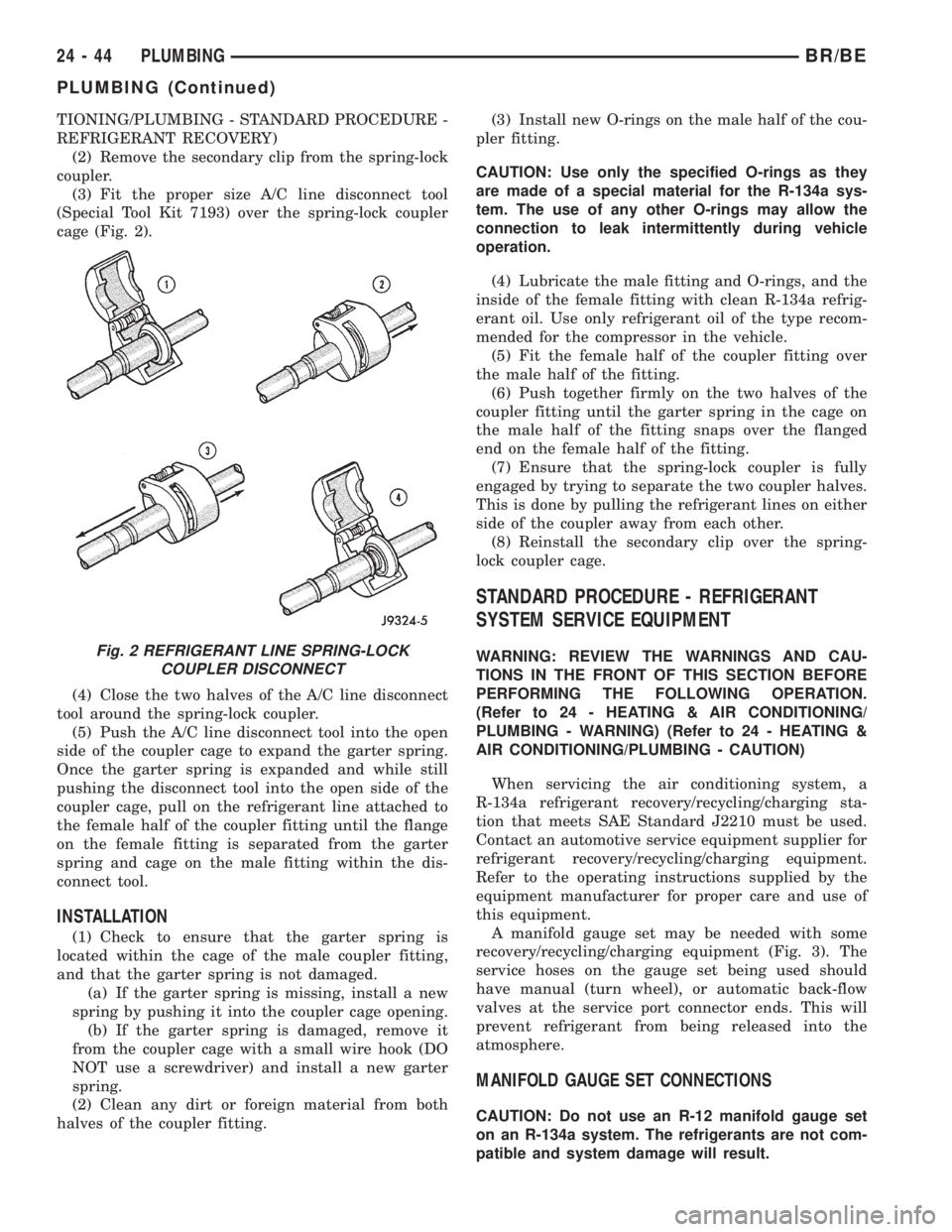
(3) Fit the proper size A/C line disconnect tool
(Special Tool Kit 7193) over the spring-lock coupler
cage (Fig. 2).
(4) Close the two halves of the A/C line disconnect
tool around the spring-lock coupler.
(5) Push the A/C line disconnect tool into the open
side of the coupler cage to expand the garter spring.
Once the garter spring is expanded and while still
pushing the disconnect tool into the open side of the
coupler cage, pull on the refrigerant line attached to
the female half of the coupler fitting until the flange
on the female fitting is separated from the garter
spring and cage on the male fitting within the dis-
connect tool.
INSTALLATION
(1) Check to ensure that the garter spring is
located within the cage of the male coupler fitting,
and that the garter spring is not damaged.
(a) If the garter spring is missing, install a new
spring by pushing it into the coupler cage opening.
(b) If the garter spring is damaged, remove it
from the coupler cage with a small wire hook (DO
NOT use a screwdriver) and install a new garter
spring.
(2) Clean any dirt or foreign material from both
halves of the coupler fitting.(3) Install new O-rings on the male half of the cou-
pler fitting.
CAUTION: Use only the specified O-rings as they
are made of a special material for the R-134a sys-
tem. The use of any other O-rings may allow the
connection to leak intermittently during vehicle
operation.
(4) Lubricate the male fitting and O-rings, and the
inside of the female fitting with clean R-134a refrig-
erant oil. Use only refrigerant oil of the type recom-
mended for the compressor in the vehicle.
(5) Fit the female half of the coupler fitting over
the male half of the fitting.
(6) Push together firmly on the two halves of the
coupler fitting until the garter spring in the cage on
the male half of the fitting snaps over the flanged
end on the female half of the fitting.
(7) Ensure that the spring-lock coupler is fully
engaged by trying to separate the two coupler halves.
This is done by pulling the refrigerant lines on either
side of the coupler away from each other.
(8) Reinstall the secondary clip over the spring-
lock coupler cage.
STANDARD PROCEDURE - REFRIGERANT
SYSTEM SERVICE EQUIPMENT
WARNING: REVIEW THE WARNINGS AND CAU-
TIONS IN THE FRONT OF THIS SECTION BEFORE
PERFORMING THE FOLLOWING OPERATION.
(Refer to 24 - HEATING & AIR CONDITIONING/
PLUMBING - WARNING) (Refer to 24 - HEATING &
AIR CONDITIONING/PLUMBING - CAUTION)
When servicing the air conditioning system, a
R-134a refrigerant recovery/recycling/charging sta-
tion that meets SAE Standard J2210 must be used.
Contact an automotive service equipment supplier for
refrigerant recovery/recycling/charging equipment.
Refer to the operating instructions supplied by the
equipment manufacturer for proper care and use of
this equipment.
A manifold gauge set may be needed with some
recovery/recycling/charging equipment (Fig. 3). The
service hoses on the gauge set being used should
have manual (turn wheel), or automatic back-flow
valves at the service port connector ends. This will
prevent refrigerant from being released into the
atmosphere.
MANIFOLD GAUGE SET CONNECTIONS
CAUTION: Do not use an R-12 manifold gauge set
on an R-134a system. The refrigerants are not com-
patible and system damage will result.
Fig. 2 REFRIGERANT LINE SPRING-LOCK
COUPLER DISCONNECT
24 - 44 PLUMBINGBR/BE
PLUMBING (Continued)
Page 2828 of 2889
Items found requiring adjustment and/or repair
should be corrected before delivery of the vehicle.
NOTE: It is the dealer's responsibility to protect
new vehicles from damage and deterioration prior
to retail delivery both before and after new vehicle
preparation.
The information includes the following features:
Inspection points are cross-referenced to the New
Vehicle Preparation Form as follows:
²Titles indicate the general area being inspected
or the types of checks being made (i.e., underhood,
body-exterior, road test, etc.).
²Sub-Titles identify the types of items to be
inspected in that area (i.e., lines/hoses, wiring, etc.).
Procedures follow a logical order to prevent dupli-
cation and wasted effort.
Tips to help you do a better job are found as
NOTES.
RECEIVING
INSPECTION
The following procedures are recommended for
your own protection upon receipt of new vehicles.
When a new car is delivered by the carrier, it should
be inspected to ensure that it is in good condition
and to determine if there is any shortage or transpor-
tation damage.
EXTERIOR
Upon receipt of a new vehicle, check immediately
for:
²Under carriage damage
²Chipped or cracked windshield, broken windows,
and loose or missing moldings and name-plates
²Dents, scrapes, scratches, chips, dirt in paints or
other damage to the body exterior
²Damaged or missing side view mirror(s)
²Missing wheel nuts
²Broken or missing lenses
²Chafing, bruises, cuts, or scrapes on tire side-
walls or tread
²Missing underhood items
²Missing fuel filler cap
²Shipped loose items-license plate bracket, spare
tire, jack and tire wrench, radio antenna, floor mats,
wheel covers, cargo nets, fuses and other items²Ensure that IOD fuse is removed
²Check battery test indicator when easily visible,
or use voltmeter (battery must be at 12.4 volts or
greater). Charge to ensure green dot-visibility, per-
manent damage may occur if battery remains in a
discharged state for any length of time.
INTERIOR
Check interior items such as:
²Rearview mirror
²Accessory control knobs
²Smokers package items
²Keys
²Radio
²Special equipment items listed on shipper
²Owner's Manual and Consumer information Bro-
chures (normally stored in the glove box).
²Cuts, abrasions or stains on interior trim.
NOTE: Remember a careful look at new vehicles
when they are received may prevent problems when
preparing vehicles for delivery to your customers.
MAJOR INSPECTION POINTS
(1) Check operation of hood latch and safety catch-
adjust as required.
(2) Check all fluids for proper level and top off
with the proper fluid as required-engine oil, auto-
matic transmission fluid, brake master cylinder,
clutch master cylinder, power steering, windshield
washer, and cooling system. (Vehicle must be at nor-
mal operating temperature for some of these checks.)
(3) Check brake, clutch, fuel, and power steering
lines and hoses for leaks and clearance from moving
and hot objects-reroute to the proper location and
tighten as required.
(4) Check battery state of charge-recharge if neces-
sary, to ensure green dot is visible or instrument
panel voltmeter indicates 12.4 volts or greater.
(5) Check routing and connections of underhood
wiring, vacuum hoses, refrigerant lines and coolant
hoses for leaks, loose connections and clearance from
moving objects reroute and tighten connections as
required. Install IOD fuse on applicable vehicles.
NOTE: Reset radio, clock, compass, etc., after
installing, if vehicle is being delivered.
BR/BENEW VEHICLE PREPARATION 30 - 3
INTRODUCTION (Continued)
Page 2830 of 2889
BRAKE MASTER CYLINDER
CAUTION: Only use fluid that meets specified
requirements (DOT 3).
NOTE: Wipe the master cylinder cover to remove
any dirt.
NOTE: On vehicles equipped with remote antilock
brakes, the fluid level check is the same as for a
normal system.
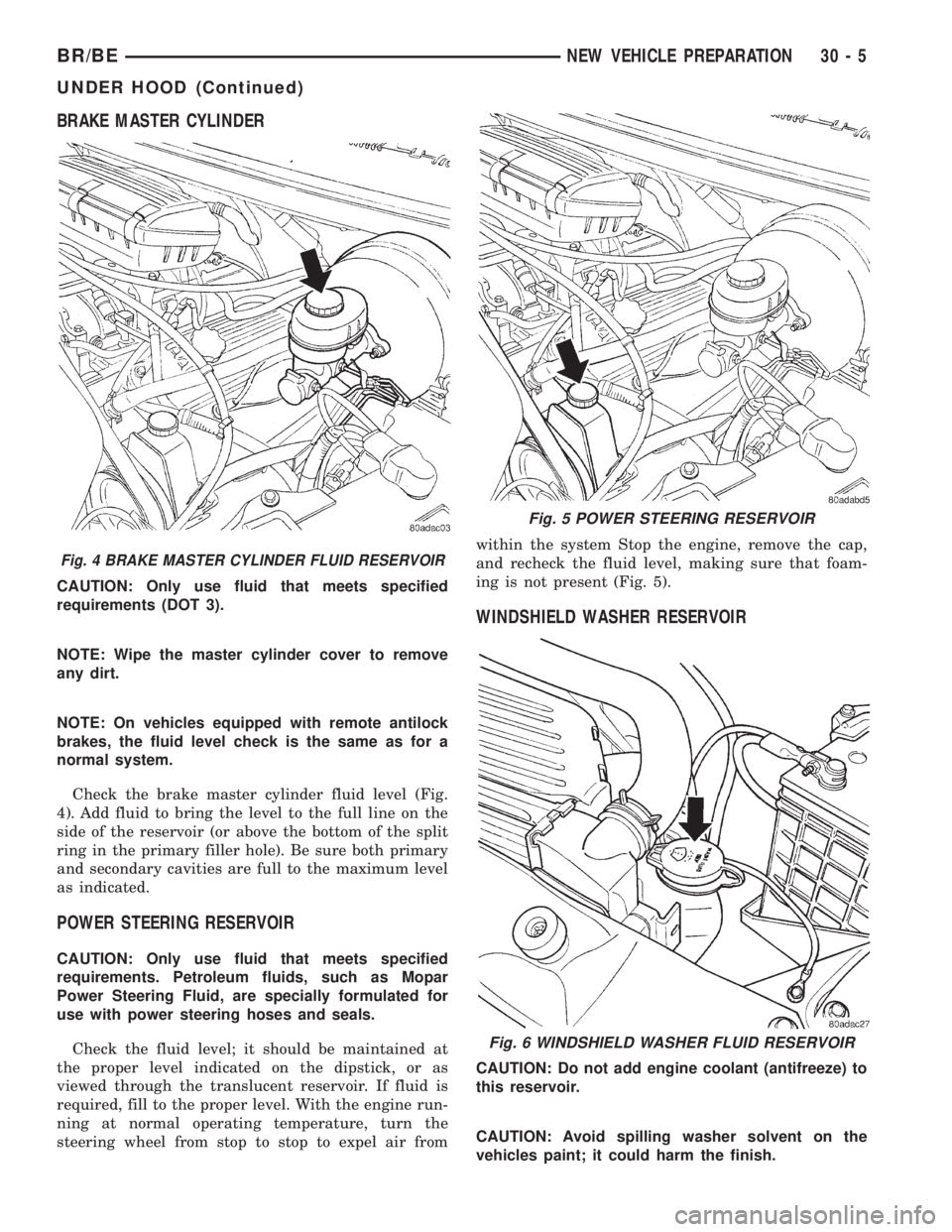
Check the brake master cylinder fluid level (Fig.
4). Add fluid to bring the level to the full line on the
side of the reservoir (or above the bottom of the split
ring in the primary filler hole). Be sure both primary
and secondary cavities are full to the maximum level
as indicated.
POWER STEERING RESERVOIR
CAUTION: Only use fluid that meets specified
requirements. Petroleum fluids, such as Mopar
Power Steering Fluid, are specially formulated for
use with power steering hoses and seals.
Check the fluid level; it should be maintained at
the proper level indicated on the dipstick, or as
viewed through the translucent reservoir. If fluid is
required, fill to the proper level. With the engine run-
ning at normal operating temperature, turn the
steering wheel from stop to stop to expel air fromwithin the system Stop the engine, remove the cap,
and recheck the fluid level, making sure that foam-
ing is not present (Fig. 5).
WINDSHIELD WASHER RESERVOIR
CAUTION: Do not add engine coolant (antifreeze) to
this reservoir.
CAUTION: Avoid spilling washer solvent on the
vehicles paint; it could harm the finish.
Fig. 4 BRAKE MASTER CYLINDER FLUID RESERVOIR
Fig. 5 POWER STEERING RESERVOIR
Fig. 6 WINDSHIELD WASHER FLUID RESERVOIR
BR/BENEW VEHICLE PREPARATION 30 - 5
UNDER HOOD (Continued)