2001 DODGE RAM wheel
[x] Cancel search: wheelPage 2666 of 2889
(2) Remove air cleaner from wheelhouse (DIESEL
ONLY).
(3) Remove coolant overflow bottle (V-10 ONLY).
(4) Remove battery tray (Refer to 8 - ELECTRI-
CAL/BATTERY SYSTEM/TRAY - REMOVAL).
(5) Remove screws attaching power distribution
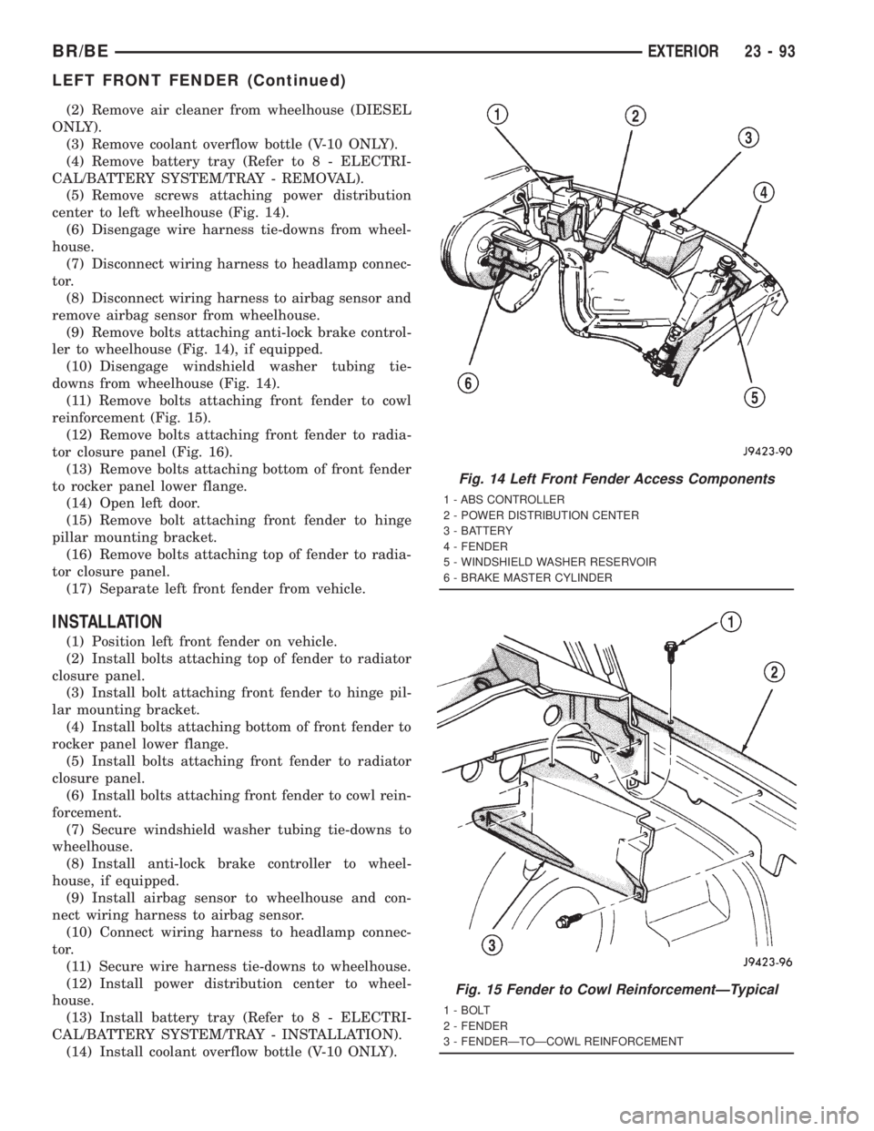
center to left wheelhouse (Fig. 14).
(6) Disengage wire harness tie-downs from wheel-
house.
(7) Disconnect wiring harness to headlamp connec-
tor.
(8) Disconnect wiring harness to airbag sensor and
remove airbag sensor from wheelhouse.
(9) Remove bolts attaching anti-lock brake control-
ler to wheelhouse (Fig. 14), if equipped.
(10) Disengage windshield washer tubing tie-
downs from wheelhouse (Fig. 14).
(11) Remove bolts attaching front fender to cowl
reinforcement (Fig. 15).
(12) Remove bolts attaching front fender to radia-
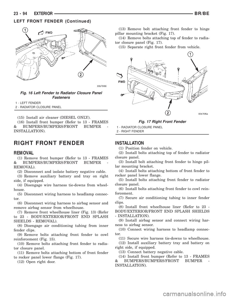
tor closure panel (Fig. 16).
(13) Remove bolts attaching bottom of front fender
to rocker panel lower flange.
(14) Open left door.
(15) Remove bolt attaching front fender to hinge
pillar mounting bracket.
(16) Remove bolts attaching top of fender to radia-
tor closure panel.
(17) Separate left front fender from vehicle.
INSTALLATION
(1) Position left front fender on vehicle.
(2) Install bolts attaching top of fender to radiator
closure panel.
(3) Install bolt attaching front fender to hinge pil-
lar mounting bracket.
(4) Install bolts attaching bottom of front fender to
rocker panel lower flange.
(5) Install bolts attaching front fender to radiator
closure panel.
(6) Install bolts attaching front fender to cowl rein-
forcement.
(7) Secure windshield washer tubing tie-downs to
wheelhouse.
(8) Install anti-lock brake controller to wheel-
house, if equipped.
(9) Install airbag sensor to wheelhouse and con-
nect wiring harness to airbag sensor.
(10) Connect wiring harness to headlamp connec-
tor.
(11) Secure wire harness tie-downs to wheelhouse.
(12) Install power distribution center to wheel-
house.
(13) Install battery tray (Refer to 8 - ELECTRI-
CAL/BATTERY SYSTEM/TRAY - INSTALLATION).
(14) Install coolant overflow bottle (V-10 ONLY).
Fig. 14 Left Front Fender Access Components
1 - ABS CONTROLLER
2 - POWER DISTRIBUTION CENTER
3 - BATTERY
4 - FENDER
5 - WINDSHIELD WASHER RESERVOIR
6 - BRAKE MASTER CYLINDER
Fig. 15 Fender to Cowl ReinforcementÐTypical
1 - BOLT
2 - FENDER
3 - FENDERÐTOÐCOWL REINFORCEMENT
BR/BEEXTERIOR 23 - 93
LEFT FRONT FENDER (Continued)
Page 2667 of 2889
(15) Install air cleaner (DIESEL ONLY).
(16) Install front bumper (Refer to 13 - FRAMES
& BUMPERS/BUMPERS/FRONT BUMPER -
INSTALLATION).
RIGHT FRONT FENDER
REMOVAL
(1) Remove front bumper (Refer to 13 - FRAMES
& BUMPERS/BUMPERS/FRONT BUMPER -
REMOVAL).
(2) Disconnect and isolate battery negative cable.
(3) Remove auxiliary battery and tray on right
side, if equipped.
(4) Disengage wire harness tie-downs from wheel-
house.
(5) Disconnect wiring harness to headlamp connec-
tor.
(6) Disconnect wiring harness to airbag sensor and
remove airbag sensor from wheelhouse.
(7) Remove front wheelhouse liner (Fig. 13) (Refer
to 23 - BODY/EXTERIOR/FRONT END SPLASH
SHIELDS - REMOVAL).
(8) Disengage air conditioning tubing from inner
fender clips.
(9) Remove bolts attaching front fender to cowl
reinforcement (Fig. 15).
(10) Remove bolts attaching front fender to radia-
tor closure panel.
(11) Remove bolts attaching bottom of front fender
to rocker panel lower flange (Fig. 17).
(12) Open right door.(13) Remove bolt attaching front fender to hinge
pillar mounting bracket (Fig. 17).
(14) Remove bolts attaching top of fender to radia-
tor closure panel (Fig. 17).
(15) Separate right front fender from vehicle.
INSTALLATION
(1) Position fender on vehicle.
(2) Install bolts attaching top of fender to radiator
closure panel.
(3) Install bolt attaching front fender to hinge pil-
lar mounting bracket.
(4) Install bolts attaching bottom of front fender to
rocker panel lower flange.
(5) Install bolts attaching front fender to radiator
closure panel.
(6) Install bolts attaching front fender to cowl rein-
forcement.
(7) Secure air conditioning tubing to inner fender
clips.
(8) Install front wheelhouse liner (Refer to 23 -
BODY/EXTERIOR/FRONT END SPLASH SHIELDS
- INSTALLATION).
(9) Install airbag sensor and connect wiring har-
ness to airbag sensor.
(10) Connect wiring harness to headlamp connec-
tor.
(11) Secure wire harness tie-downs to wheelhouse.
(12) Install auxiliary battery tray and battery on
right side, if equipped.
(13) Connect battery negative cable.
(14) Install front bumper (Refer to 13 - FRAMES
& BUMPERS/BUMPERS/FRONT BUMPER -
INSTALLATION).
Fig. 16 Left Fender to Radiator Closure Panel
Fasteners
1 - LEFT FENDER
2 - RADIATOR CLOSURE PANEL
Fig. 17 Right Front Fender
1 - RADIATOR CLOSURE PANEL
2 - RIGHT FENDER
23 - 94 EXTERIORBR/BE
LEFT FRONT FENDER (Continued)
Page 2668 of 2889
FUEL FILL DOOR
REMOVAL
(1) Open fuel fill door.
(2) Remove bolts attaching fuel fill door to cargo
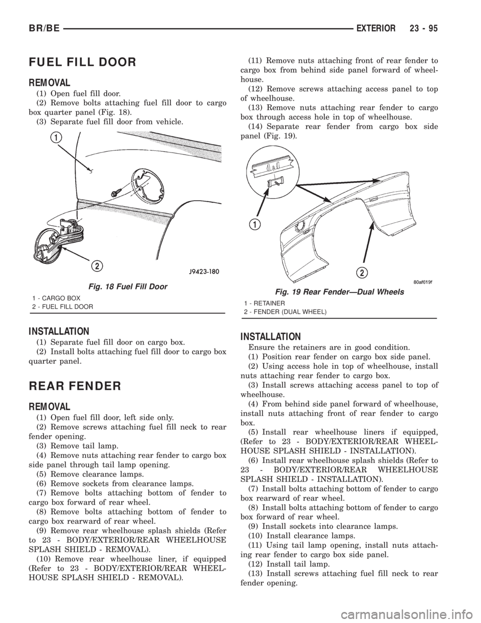
box quarter panel (Fig. 18).
(3) Separate fuel fill door from vehicle.
INSTALLATION
(1) Separate fuel fill door on cargo box.
(2) Install bolts attaching fuel fill door to cargo box
quarter panel.
REAR FENDER
REMOVAL
(1) Open fuel fill door, left side only.
(2) Remove screws attaching fuel fill neck to rear
fender opening.
(3) Remove tail lamp.
(4) Remove nuts attaching rear fender to cargo box
side panel through tail lamp opening.
(5) Remove clearance lamps.
(6) Remove sockets from clearance lamps.
(7) Remove bolts attaching bottom of fender to
cargo box forward of rear wheel.
(8) Remove bolts attaching bottom of fender to
cargo box rearward of rear wheel.
(9) Remove rear wheelhouse splash shields (Refer
to 23 - BODY/EXTERIOR/REAR WHEELHOUSE
SPLASH SHIELD - REMOVAL).
(10) Remove rear wheelhouse liner, if equipped
(Refer to 23 - BODY/EXTERIOR/REAR WHEEL-
HOUSE SPLASH SHIELD - REMOVAL).(11) Remove nuts attaching front of rear fender to
cargo box from behind side panel forward of wheel-
house.
(12) Remove screws attaching access panel to top
of wheelhouse.
(13) Remove nuts attaching rear fender to cargo
box through access hole in top of wheelhouse.
(14) Separate rear fender from cargo box side
panel (Fig. 19).
INSTALLATION
Ensure the retainers are in good condition.
(1) Position rear fender on cargo box side panel.
(2) Using access hole in top of wheelhouse, install
nuts attaching rear fender to cargo box.
(3) Install screws attaching access panel to top of
wheelhouse.
(4) From behind side panel forward of wheelhouse,
install nuts attaching front of rear fender to cargo
box.
(5) Install rear wheelhouse liners if equipped,
(Refer to 23 - BODY/EXTERIOR/REAR WHEEL-
HOUSE SPLASH SHIELD - INSTALLATION).
(6) Install rear wheelhouse splash shields (Refer to
23 - BODY/EXTERIOR/REAR WHEELHOUSE
SPLASH SHIELD - INSTALLATION).
(7) Install bolts attaching bottom of fender to cargo
box rearward of rear wheel.
(8) Install bolts attaching bottom of fender to cargo
box forward of rear wheel.
(9) Install sockets into clearance lamps.
(10) Install clearance lamps.
(11) Using tail lamp opening, install nuts attach-
ing rear fender to cargo box side panel.
(12) Install tail lamp.
(13) Install screws attaching fuel fill neck to rear
fender opening.
Fig. 18 Fuel Fill Door
1 - CARGO BOX
2 - FUEL FILL DOORFig. 19 Rear FenderÐDual Wheels
1 - RETAINER
2 - FENDER (DUAL WHEEL)
BR/BEEXTERIOR 23 - 95
Page 2669 of 2889
REAR SPLASH SHIELD
REMOVAL
(1) Remove screws holding rear splash shield to
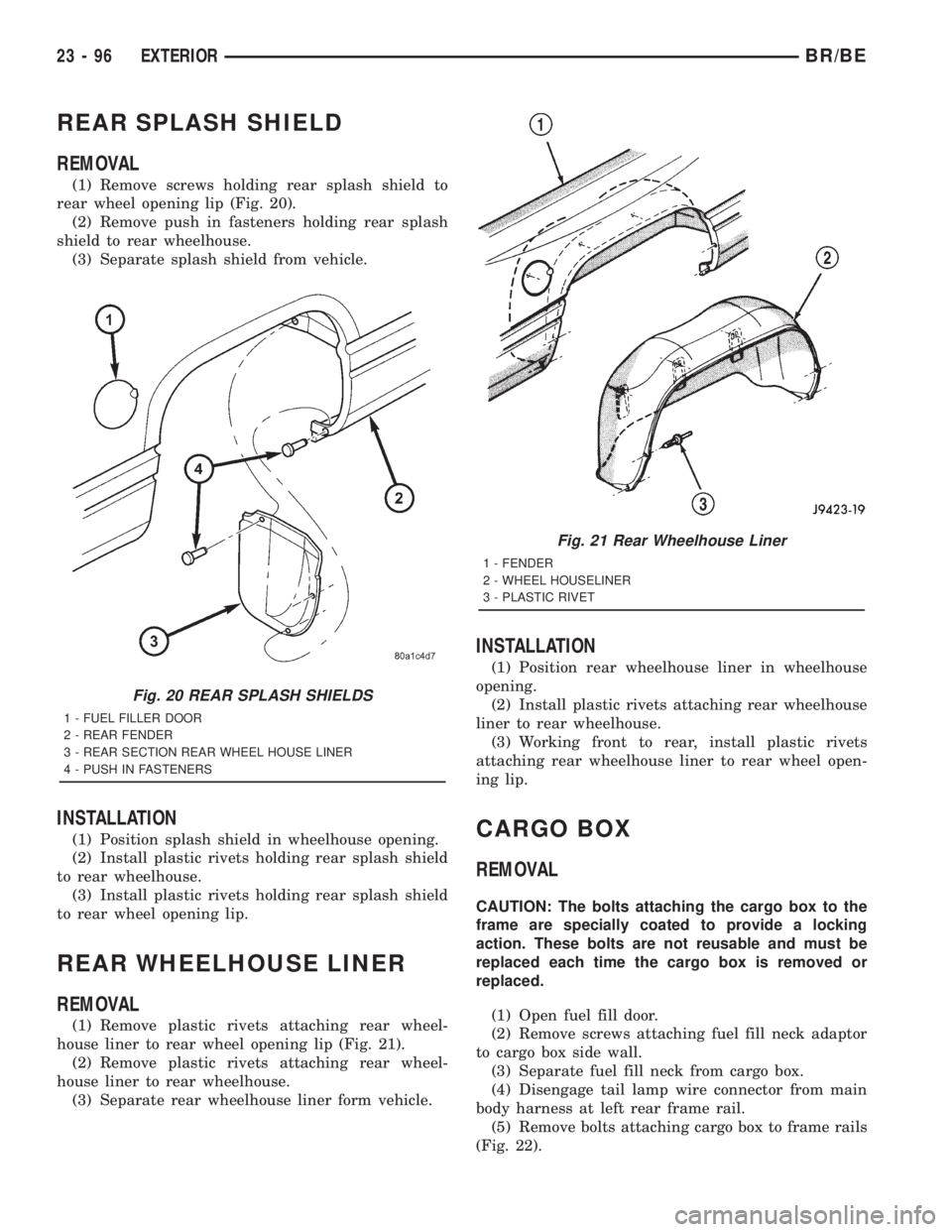
rear wheel opening lip (Fig. 20).
(2) Remove push in fasteners holding rear splash
shield to rear wheelhouse.
(3) Separate splash shield from vehicle.
INSTALLATION
(1) Position splash shield in wheelhouse opening.
(2) Install plastic rivets holding rear splash shield
to rear wheelhouse.
(3) Install plastic rivets holding rear splash shield
to rear wheel opening lip.
REAR WHEELHOUSE LINER
REMOVAL
(1) Remove plastic rivets attaching rear wheel-
house liner to rear wheel opening lip (Fig. 21).
(2) Remove plastic rivets attaching rear wheel-
house liner to rear wheelhouse.
(3) Separate rear wheelhouse liner form vehicle.
INSTALLATION
(1) Position rear wheelhouse liner in wheelhouse
opening.
(2) Install plastic rivets attaching rear wheelhouse
liner to rear wheelhouse.
(3) Working front to rear, install plastic rivets
attaching rear wheelhouse liner to rear wheel open-
ing lip.
CARGO BOX
REMOVAL
CAUTION: The bolts attaching the cargo box to the
frame are specially coated to provide a locking
action. These bolts are not reusable and must be
replaced each time the cargo box is removed or
replaced.
(1) Open fuel fill door.
(2) Remove screws attaching fuel fill neck adaptor
to cargo box side wall.
(3) Separate fuel fill neck from cargo box.
(4) Disengage tail lamp wire connector from main
body harness at left rear frame rail.
(5) Remove bolts attaching cargo box to frame rails
(Fig. 22).
Fig. 20 REAR SPLASH SHIELDS
1 - FUEL FILLER DOOR
2 - REAR FENDER
3 - REAR SECTION REAR WHEEL HOUSE LINER
4 - PUSH IN FASTENERS
Fig. 21 Rear Wheelhouse Liner
1 - FENDER
2 - WHEEL HOUSELINER
3 - PLASTIC RIVET
23 - 96 EXTERIORBR/BE
Page 2679 of 2889
REMOVAL
WARNING: ON VEHICLES EQUIPPED WITH AIR-
BAGS, DISABLE THE AIRBAG SYSTEM BEFORE
ATTEMPTING ANY STEERING WHEEL, STEERING
COLUMN, OR INSTRUMENT PANEL COMPONENT
DIAGNOSIS OR SERVICE. DISCONNECT AND ISO-
LATE THE BATTERY NEGATIVE (GROUND) CABLE,
THEN WAIT TWO MINUTES FOR THE AIRBAG SYS-
TEM CAPACITOR TO DISCHARGE BEFORE PER-
FORMING FURTHER DIAGNOSIS OR SERVICE. THIS
IS THE ONLY SURE WAY TO DISABLE THE AIRBAG
SYSTEM. FAILURE TO TAKE THE PROPER PRE-
CAUTIONS COULD RESULT IN ACCIDENTAL AIR-
BAG DEPLOYMENT AND POSSIBLE PERSONAL
INJURY.
NOTE: Before starting this procedure, be certain to
turn the steering wheel until the front wheels are in
the straight-ahead position.
(1) Disconnect and isolate the battery negative
cable.
(2) Remove the Airbag Control Module (ACM) and
bracket from the floor panel transmission tunnel.
(Refer to 8 - ELECTRICAL/RESTRAINTS/AIRBAG
CONTROL MODULE - REMOVAL).
(3) Remove the trim from the left and right cowl
side inner panels. (Refer to 23 - BODY/INTERIOR/
COWL TRIM COVER - REMOVAL).
(4) Remove the steering column opening cover
from the instrument panel. (Refer to 23 - BODY/IN-
STRUMENT PANEL/STEERING COLUMN OPEN-
ING COVER - REMOVAL).
(5) Remove the two screws that secure the inside
hood latch release handle to the instrument panel
lower reinforcement and lower the release handle to
the floor.
(6) Disconnect the clockspring pigtail wire connec-
tor from the instrument panel wire harness connec-
tor located on the instrument panel lower
reinforcement.
(7) If the vehicle is so equipped, disconnect the
overdrive lockout switch pigtail wire connector from
the instrument panel wire harness connector near
the instrument panel lower reinforcement.
(8) Remove the steering column from the vehicle,
but do not remove the driver airbag, the steering
wheel, or the switches from the column. Be certain
that the steering wheel is locked and secured from
rotation to prevent the loss of clockspring centering.
(Refer to 19 - STEERING/COLUMN - REMOVAL).
(9) From under the driver side of the instrument
panel, perform the following:
(a) Disengage the park brake release handle
linkage rod from the park brake mechanism on theleft cowl side inner panel. (Refer to 5 - BRAKES/
PARKING BRAKE/RELEASE - REMOVAL).
(b) Disconnect the instrument panel wire har-
ness connector from the park brake switch on the
park brake mechanism.
(c) Disconnect the three connectors (one from the
body wire harness, and two from the headlamp and
dash wire harness) from the three connector recep-
tacles located closest to the dash panel on the back
of the Junction Block (JB).
(d) Remove the screw from the center of the
headlamp and dash wire harness to instrument
panel wire harness bulkhead connector and discon-
nect the connector.
(e) Disconnect the instrument panel wire har-
ness to door wire harness connector located directly
below the instrument panel wire harness to head-
lamp and dash wire harness bulkhead connector.
(f) If the vehicle is equipped with the Infinity
sound system option, disconnect the Infinity wire
harness connector from the instrument panel wire
harness connector that is secured to the outboard
side of the instrument panel wire harness to head-
lamp and dash wire harness bulkhead connector.
(g) Disconnect the instrument panel wire har-
ness connector from the stop lamp switch.
(h) Disconnect the heater-A/C housing vacuum
harness connector from the heater-A/C control vac-
uum harness connector located near the left end of
the heater-A/C housing.
(10) From under the passenger side of the instru-
ment panel, disconnect the two halves of the radio
antenna coaxial cable connector.
(11) Loosen the right and left instrument panel
cowl side roll-down bracket screws about 13 mm
(0.50 inch) (Fig. 1).
(12) Remove the five screws that secure the top of
the instrument panel to the top of the dash panel,
removing the center screw last.
(13) Roll down the instrument panel and install a
temporary hook in the center hole on top of the
instrument panel. Secure the other end of the hook
to the center hole in the top of the dash panel. The
hook should support the instrument panel in its
rolled down position about 46 cm (18 inches) from
the dash panel.
(14) With the instrument panel supported in the
roll-down position, disconnect the instrument panel
wire harness connectors from the heater-A/C housing
wire harness connectors.
(15) With the aid of an assistant, remove the tem-
porary hook and lift the instrument panel assembly
off of the roll-down bracket screws and remove it
from the vehicle.
23 - 106 INSTRUMENT PANEL SYSTEMBR/BE
INSTRUMENT PANEL SYSTEM (Continued)
Page 2680 of 2889
INSTALLATION
WARNING: ON VEHICLES EQUIPPED WITH AIR-
BAGS, DISABLE THE AIRBAG SYSTEM BEFORE
ATTEMPTING ANY STEERING WHEEL, STEERING
COLUMN, OR INSTRUMENT PANEL COMPONENT
DIAGNOSIS OR SERVICE. DISCONNECT AND ISO-
LATE THE BATTERY NEGATIVE (GROUND) CABLE,
THEN WAIT TWO MINUTES FOR THE AIRBAG SYS-
TEM CAPACITOR TO DISCHARGE BEFORE PER-
FORMING FURTHER DIAGNOSIS OR SERVICE. THIS
IS THE ONLY SURE WAY TO DISABLE THE AIRBAG
SYSTEM. FAILURE TO TAKE THE PROPER PRE-
CAUTIONS COULD RESULT IN ACCIDENTAL AIR-
BAG DEPLOYMENT AND POSSIBLE PERSONAL
INJURY.
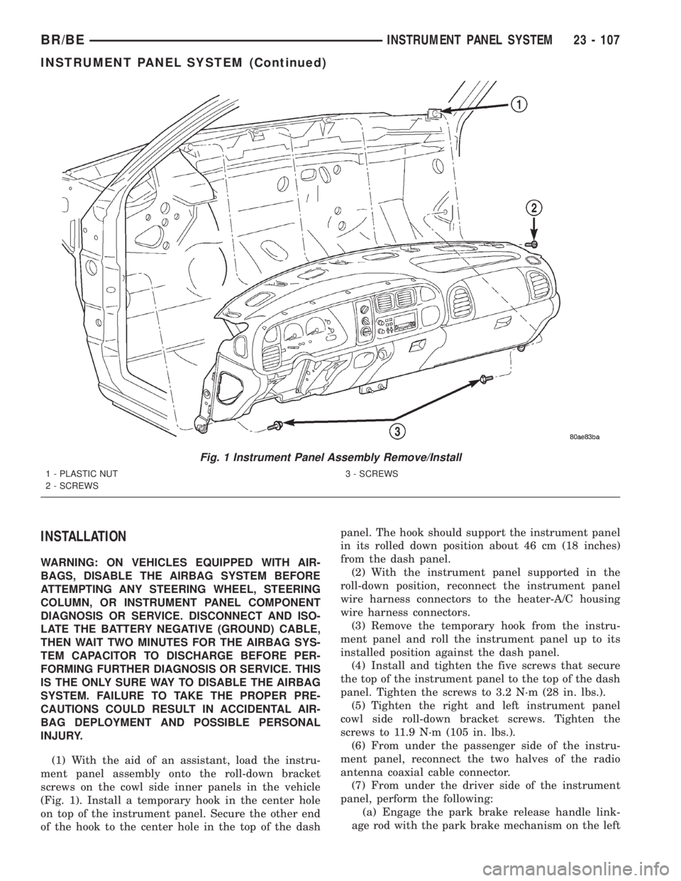
(1) With the aid of an assistant, load the instru-
ment panel assembly onto the roll-down bracket
screws on the cowl side inner panels in the vehicle
(Fig. 1). Install a temporary hook in the center hole
on top of the instrument panel. Secure the other end
of the hook to the center hole in the top of the dashpanel. The hook should support the instrument panel
in its rolled down position about 46 cm (18 inches)
from the dash panel.
(2) With the instrument panel supported in the
roll-down position, reconnect the instrument panel
wire harness connectors to the heater-A/C housing
wire harness connectors.
(3) Remove the temporary hook from the instru-
ment panel and roll the instrument panel up to its
installed position against the dash panel.
(4) Install and tighten the five screws that secure
the top of the instrument panel to the top of the dash
panel. Tighten the screws to 3.2 N´m (28 in. lbs.).
(5) Tighten the right and left instrument panel
cowl side roll-down bracket screws. Tighten the
screws to 11.9 N´m (105 in. lbs.).
(6) From under the passenger side of the instru-
ment panel, reconnect the two halves of the radio
antenna coaxial cable connector.
(7) From under the driver side of the instrument
panel, perform the following:
(a) Engage the park brake release handle link-
age rod with the park brake mechanism on the left
Fig. 1 Instrument Panel Assembly Remove/Install
1 - PLASTIC NUT
2 - SCREWS3 - SCREWS
BR/BEINSTRUMENT PANEL SYSTEM 23 - 107
INSTRUMENT PANEL SYSTEM (Continued)
Page 2681 of 2889
cowl side inner panel. (Refer to 5 - BRAKES/PARK-
ING BRAKE/RELEASE - INSTALLATION).
(b) Reconnect the instrument panel wire harness
connector to the park brake switch on the park
brake mechanism.
(c) Reconnect the three connectors (one from the
body wire harness, and two from the headlamp and
dash wire harness) to the three connector recepta-
cles located closest to the dash panel on the back of
the Junction Block (JB).
(d) Reconnect the headlamp and dash wire har-
ness to instrument panel wire harness bulkhead
connector and tighten the screw in the center of
the connector. Tighten the screw to 3.5 N´m (31 in.
lbs.).
(e) Reconnect the instrument panel wire harness
to door wire harness connector located directly
below the instrument panel wire harness to head-
lamp and dash wire harness bulkhead connector.
(f) If the vehicle is equipped with the Infinity
sound system option, reconnect the Infinity wire
harness connector to the instrument panel wire
harness connector that is secured to the outboard
side of the instrument panel wire harness to head-
lamp and dash wire harness bulkhead connector.
(g) Reconnect the instrument panel wire harness
connector to the stop lamp switch.
(h) Reconnect the heater-A/C housing vacuum
harness connector to the heater-A/C control vac-
uum harness connector located near the left end of
the heater-A/C housing.
(8) Reinstall the steering column into the vehicle.
Be certain that the steering wheel was locked and
secured from rotation to prevent the loss of clock-
spring centering. (Refer to 19 - STEERING/COL-
UMN - INSTALLATION).
(9) If the vehicle is so equipped, reconnect the
overdrive lockout switch pigtail wire connector to the
instrument panel wire harness connector near the
instrument panel lower reinforcement.
(10) Reconnect the clockspring pigtail wire connec-
tor to the instrument panel wire harness connector
at the instrument panel lower reinforcement.
(11) Position the inside hood latch release handle
to the instrument panel lower reinforcement.
(12) Install and tighten the two screws that secure
the inside hood latch release handle to the instru-
ment panel lower reinforcement. Tighten the screws
to 2.8 N´m (25 in. lbs.).
(13) Reinstall the steering column opening cover
onto the instrument panel. (Refer to 23 - BODY/IN-
STRUMENT PANEL/STEERING COLUMN OPEN-
ING COVER - INSTALLATION).
(14) Reinstall the trim onto the left and right cowl
side inner panels. (Refer to 23 - BODY/INTERIOR/
COWL TRIM COVER - INSTALLATION).(15) Reinstall the Airbag Control Module (ACM)
and bracket onto the floor panel transmission tunnel.
(Refer to 8 - ELECTRICAL/RESTRAINTS/AIRBAG
CONTROL MODULE - INSTALLATION).
(16) Reconnect the battery negative cable.
ASH RECEIVER
REMOVAL
WARNING: ON VEHICLES EQUIPPED WITH AIR-
BAGS, DISABLE THE AIRBAG SYSTEM BEFORE
ATTEMPTING ANY STEERING WHEEL, STEERING
COLUMN, OR INSTRUMENT PANEL COMPONENT
DIAGNOSIS OR SERVICE. DISCONNECT AND ISO-
LATE THE BATTERY NEGATIVE (GROUND) CABLE,
THEN WAIT TWO MINUTES FOR THE AIRBAG SYS-
TEM CAPACITOR TO DISCHARGE BEFORE PER-
FORMING FURTHER DIAGNOSIS OR SERVICE. THIS
IS THE ONLY SURE WAY TO DISABLE THE AIRBAG
SYSTEM. FAILURE TO TAKE THE PROPER PRE-
CAUTIONS COULD RESULT IN ACCIDENTAL AIR-
BAG DEPLOYMENT AND POSSIBLE PERSONAL
INJURY.
(1) Disconnect and isolate the battery negative
cable.
(2) Open the instrument panel ash receiver.
(3) From the open position, close the ash receiver
slightly and pull it straight back far enough to disen-
gage it from the pivot pins in the lower instrument
panel.
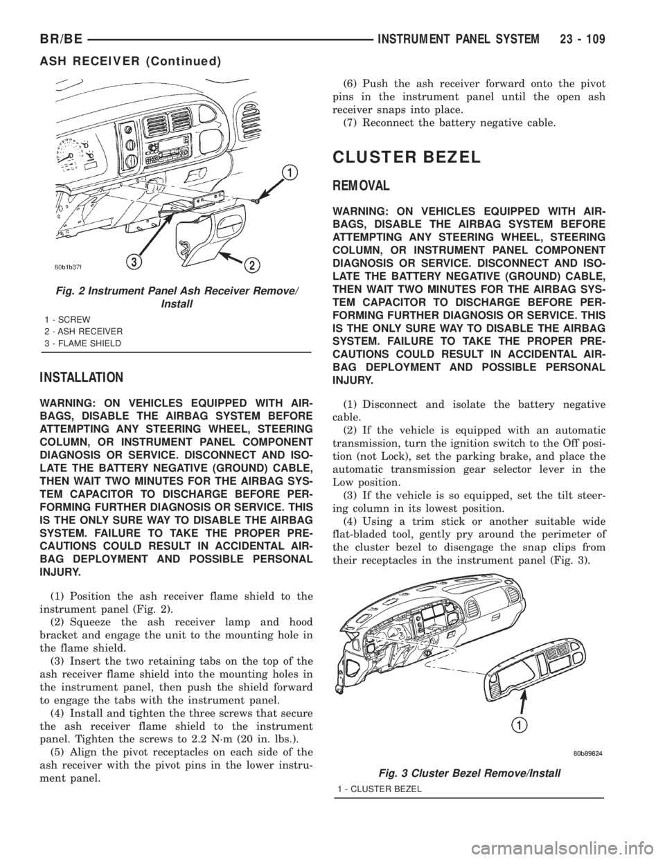
(4) Remove the three screws that secure the ash
receiver flame shield to the lower instrument panel
(Fig. 2).
(5) Pull the ash receiver flame shield out from the
instrument panel far enough to disengage the two
retaining tabs on the top of the shield from the
mounting holes in the instrument panel.
(6) Lower the flame shield from the instrument
panel far enough to access the ash receiver lamp and
hood.
(7) Squeeze the ash receiver lamp and hood
bracket to disengage the unit from the mounting hole
in the flame shield.
(8) Remove the ash receiver flame shield from the
instrument panel.
23 - 108 INSTRUMENT PANEL SYSTEMBR/BE
INSTRUMENT PANEL SYSTEM (Continued)
Page 2682 of 2889
INSTALLATION
WARNING: ON VEHICLES EQUIPPED WITH AIR-
BAGS, DISABLE THE AIRBAG SYSTEM BEFORE
ATTEMPTING ANY STEERING WHEEL, STEERING
COLUMN, OR INSTRUMENT PANEL COMPONENT
DIAGNOSIS OR SERVICE. DISCONNECT AND ISO-
LATE THE BATTERY NEGATIVE (GROUND) CABLE,
THEN WAIT TWO MINUTES FOR THE AIRBAG SYS-
TEM CAPACITOR TO DISCHARGE BEFORE PER-
FORMING FURTHER DIAGNOSIS OR SERVICE. THIS
IS THE ONLY SURE WAY TO DISABLE THE AIRBAG
SYSTEM. FAILURE TO TAKE THE PROPER PRE-
CAUTIONS COULD RESULT IN ACCIDENTAL AIR-
BAG DEPLOYMENT AND POSSIBLE PERSONAL
INJURY.
(1) Position the ash receiver flame shield to the
instrument panel (Fig. 2).
(2) Squeeze the ash receiver lamp and hood
bracket and engage the unit to the mounting hole in
the flame shield.
(3) Insert the two retaining tabs on the top of the
ash receiver flame shield into the mounting holes in
the instrument panel, then push the shield forward
to engage the tabs with the instrument panel.
(4) Install and tighten the three screws that secure
the ash receiver flame shield to the instrument
panel. Tighten the screws to 2.2 N´m (20 in. lbs.).
(5) Align the pivot receptacles on each side of the
ash receiver with the pivot pins in the lower instru-
ment panel.(6) Push the ash receiver forward onto the pivot
pins in the instrument panel until the open ash
receiver snaps into place.
(7) Reconnect the battery negative cable.
CLUSTER BEZEL
REMOVAL
WARNING: ON VEHICLES EQUIPPED WITH AIR-
BAGS, DISABLE THE AIRBAG SYSTEM BEFORE
ATTEMPTING ANY STEERING WHEEL, STEERING
COLUMN, OR INSTRUMENT PANEL COMPONENT
DIAGNOSIS OR SERVICE. DISCONNECT AND ISO-
LATE THE BATTERY NEGATIVE (GROUND) CABLE,
THEN WAIT TWO MINUTES FOR THE AIRBAG SYS-
TEM CAPACITOR TO DISCHARGE BEFORE PER-
FORMING FURTHER DIAGNOSIS OR SERVICE. THIS
IS THE ONLY SURE WAY TO DISABLE THE AIRBAG
SYSTEM. FAILURE TO TAKE THE PROPER PRE-
CAUTIONS COULD RESULT IN ACCIDENTAL AIR-
BAG DEPLOYMENT AND POSSIBLE PERSONAL
INJURY.
(1) Disconnect and isolate the battery negative
cable.
(2) If the vehicle is equipped with an automatic
transmission, turn the ignition switch to the Off posi-
tion (not Lock), set the parking brake, and place the
automatic transmission gear selector lever in the
Low position.
(3) If the vehicle is so equipped, set the tilt steer-
ing column in its lowest position.
(4) Using a trim stick or another suitable wide
flat-bladed tool, gently pry around the perimeter of
the cluster bezel to disengage the snap clips from
their receptacles in the instrument panel (Fig. 3).
Fig. 2 Instrument Panel Ash Receiver Remove/
Install
1 - SCREW
2 - ASH RECEIVER
3 - FLAME SHIELD
Fig. 3 Cluster Bezel Remove/Install
1 - CLUSTER BEZEL
BR/BEINSTRUMENT PANEL SYSTEM 23 - 109
ASH RECEIVER (Continued)