2001 DODGE RAM wheel
[x] Cancel search: wheelPage 1600 of 2889
WARNING: THE AIRBAG SYSTEM IS A SENSITIVE,
COMPLEX ELECTRO-MECHANICAL UNIT. BEFORE
ATTEMPTING TO DIAGNOSE, REMOVE OR INSTALL
THE AIRBAG SYSTEM COMPONENTS YOU MUST
FIRST DISCONNECT AND ISOLATE THE BATTERY
NEGATIVE (GROUND) CABLE. THEN WAIT TWO
MINUTES FOR THE SYSTEM CAPACITOR TO DIS-
CHARGE. FAILURE TO DO SO COULD RESULT IN
ACCIDENTAL DEPLOYMENT OF THE AIRBAG AND
POSSIBLE PERSONAL INJURY. THE FASTENERS,
SCREWS, AND BOLTS, ORIGINALLY USED FOR
THE AIRBAG COMPONENTS, HAVE SPECIAL COAT-
INGS AND ARE SPECIFICALLY DESIGNED FOR THE
AIRBAG SYSTEM. THEY MUST NEVER BE
REPLACED WITH ANY SUBSTITUTES. ANYTIME A
NEW FASTENER IS NEEDED, REPLACE WITH THE
CORRECT FASTENERS PROVIDED IN THE SERVICE
PACKAGE OR FASTENERS LISTED IN THE PARTS
BOOKS.
CAUTION: Do not hammer on steering column shaft
or shift tube. This may cause the shaft/shift tube to
collapse or damage the bearing.
CAUTION: Do not attempt to remove the pivot pins
to disassemble the tilting mechanism. Do not
remove shaft lock plate, plate retainer, park lock
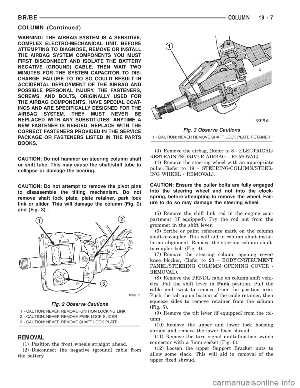
link or slider. This will damage the column (Fig. 2)
and (Fig. 3) .
REMOVAL
(1) Position the front wheels straight ahead.
(2) Disconnect the negative (ground) cable from
the battery.(3) Remove the airbag, (Refer to 8 - ELECTRICAL/
RESTRAINTS/DRIVER AIRBAG - REMOVAL).
(4) Remove the steering wheel with an appropriate
puller,(Refer to 19 - STEERING/COLUMN/STEER-
ING WHEEL - REMOVAL).
CAUTION: Ensure the puller bolts are fully engaged
into the steering wheel and not into the clock-
spring, before attempting to remove the wheel. Fail-
ure to do so may damage the steering wheel.
(5) Remove the shift link rod in the engine com-
partment (if equipped). Pry the rod out from the
grommet in the shift lever.
(6) Scribe or paint reference mark on the column
shaft-to-coupler. This will aid in column shaft instal-
lation alignment. Remove the steering column shaft-
to-coupler bolt (Fig. 4).
(7) Remove the steering column opening cover/
knee blocker, (Refer to 23 - BODY/INSTRUMENT
PANEL/STEERING COLUMN OPENING COVER -
REMOVAL).
(8) Remove the PRNDL cable on column shift vehi-
cles. Put the shift lever inParkposition. Pull the
cable and twist to remove from the position arm.
Push the tab up on bottom of the cable retainer, then
squeeze sides to remove retainer from the column
(Fig. 5).
(9) Remove the tilt lever (if equipped) from the col-
umn.
(10) Remove the upper and lower lock housing
shroud and remove the lower fixed shroud.
(11) Remove the turn signal multi-function switch
connector with a 7mm socket (Fig. 6).
(12) Loosen the upper Support Bracket nuts to
allow some slack. This will aid in removal of the
upper fixed shroud.
Fig. 2 Observe Cautions
1 - CAUTION: NEVER REMOVE IGNITION LOCKING LINK
2 - CAUTION: NEVER REMOVE PARK LOCK SLIDER
3 - CAUTION: NEVER REMOVE SHAFT LOCK PLATE
Fig. 3 Observe Cautions
1 - CAUTION: NEVER REMOVE SHAFT LOCK PLATE RETAINER
BR/BECOLUMN 19 - 7
COLUMN (Continued)
Page 1602 of 2889

NOTE: A new grommet should be used when ever
the rod is disconnected from the lever.
(3) Remove the shipping lock pin if necessary.
(4) Install the column through the floor pan.
(5) Position the column bracket breakaway cap-
sules on the mounting studs. Install, butloose
assemblethe two upper bracket nuts.
(6) With the front wheels in the straight-ahead
position. Align steering column shaft to the coupler.
Install anewpinch bolt and tighten to 49 N´m (36
ft. lbs.).
(7) Clip the wiring harness on the steering column.
Connect the multi- function switch wiring and
tighten with 7mm socket.
(8) Install the upper fixed shroud.
(9) Be sure both breakaway capsules are fully
seated in the slots in the column support bracket.
Pull the column rearward then tighten upper bracket
nuts to 12 N´m (105 in. lbs.).
(10) Tighten the toe plate to floor pan attaching
nuts to 22.5 N´m (200 in. lbs.).
(11) Install the wiring connections to the column.
Install the lower fixed shroud.(12) Column shift vehicles, install the PRNDL
driver cable. Place shifter in Park position. If indica-
tor needs adjusting, turn thumb screw on cable
retainer to adjust cable.
(13) Install the lock housing shrouds. Install the
tilt lever (if equipped).
(14) Install the knee blocker and steering column
opening cover, (Refer to 23 - BODY/INSTRUMENT
PANEL/STEERING COLUMN OPENING COVER -
INSTALLATION).
(15) Install steering wheel and tighten nut to 61
N´m (45 ft. lbs.), (Refer to 19 - STEERING/COL-
UMN/STEERING WHEEL - INSTALLATION).
(16) Install the airbag, (Refer to 8 - ELECTRICAL/
RESTRAINTS/DRIVER AIRBAG - INSTALLATION).
(17) Column shift vehicles, connect the shift link
rod to the transmission shift lever. Use multi-purpose
lubricant, or an equivalent product, to aid the instal-
lation.
(18) Install the battery ground (negative) cable.
(19) Verify operation of the automatic transmission
shift linkage and adjust as necessary, (Refer to 21 -
TRANSMISSION/TRANSAXLE/AUTOMATIC -
44RE/GEAR SHIFT CABLE - ADJUSTMENTS).
SPECIFICATIONS
TORQUE CHART
TORQUE SPECIFICATIONS
DESCRIPTION N´m Ft. Lbs. In. Lbs.
Steering Wheel
Nut61 45 Ð
Steering Coupler
Bolt49 36 Ð
Steering Column
Upper Bracket12 Ð 105
Steering Column
Toe Plate23 Ð 200
KEY-IN IGNITION SWITCH
DESCRIPTION
The key-in ignition switch is integral to the igni-
tion switch, which is mounted on the right side of the
steering column. It closes a path to ground for the
Central Timer Module (CTM) when the ignition key
is inserted in the ignition lock cylinder and thedriver door ajar switch is closed (driver door is open).
The key-in ignition switch opens the ground path
when the key is removed from the ignition lock cyl-
inder. The ground path is also opened when the
driver door ajar switch is open (driver door is closed).
The key-in ignition switch cannot be repaired and,
if faulty or damaged, the entire ignition switch must
be replaced,(Refer to 19 - STEERING/COLUMN/IG-
NITION SWITCH - REMOVAL).
BR/BECOLUMN 19 - 9
COLUMN (Continued)
Page 1603 of 2889
DIAGNOSIS AND TESTING - IGNITION SWITCH
AND KEY LOCK CYLINDER
ELECTRICAL DIAGNOSIS
For ignition switch electrical schematics, refer to
Ignition Switch in the appropriate section of Electri-
cal Wiring Diagrams.
MECHANICAL DIAGNOSIS (KEY DIFFICULT TO
ROTATE)
Vehicles equipped with an automatic trans-
mission and a floor mounted shifter:a cable is
used to connect the interlock device in the steering
column assembly, to the transmission floor shift
lever. This interlock device is used to lock the trans-
mission shifter in the PARK position when the key
lock cylinder is rotated to the LOCKED or ACCES-
SORY position. The interlock device within the steer-
ing column is not serviceable. If repair is necessary,
the steering column assembly must be replaced.
(Refer to 19 - STEERING/COLUMN - REMOVAL).
If the ignition key is difficult to rotate to or from
the LOCK or ACCESSORY position, it may not be
the fault of the key cylinder or the steering column
components. The brake transmission shift interlock
cable may be out of adjustment. Refer to Brake
Transmission Shift Interlock Cable Adjustment in
Transmissions for adjustment procedures.
Vehicles equipped with an automatic trans-
mission and a steering column mounted shifter:
an interlock device is located within the steering col-
umn. This interlock device is used to lock the trans-
mission shifter in the PARK position when the key
lock cylinder is in the LOCKED or ACCESSORY
position. If it is difficult to rotate the key to or from
the LOCK or ACCESSORY position, the interlock
device within the steering column may be defective.
This device is not serviceable. If repair is necessary,
the steering column assembly must be replaced.
(Refer to 19 - STEERING/COLUMN - REMOVAL).
Vehicles equipped with a manual transmis-
sion and a floor mounted shifter:on certain mod-
els, a lever is located on the steering column behind
the ignition key lock cylinder. The lever must be
manually operated to allow rotation of the ignition
key lock cylinder to the LOCK or ACCESSORY posi-
tion. If it is difficult to rotate the key to the LOCK or
ACCESSORY position, the lever mechanism may be
defective. This mechanism is not serviceable. If
repair is necessary, the steering column assembly
must be replaced. (Refer to 19 - STEERING/COL-
UMN - REMOVAL).
On other models, the ignition key cylinder must be
depressed to allow it to be rotated into the LOCK or
ACCESSORY position. If it is difficult to rotate the
key to the LOCK or ACCESSORY position, the lockmechanism within the steering column may be defec-
tive. This mechanism is not serviceable. If repair is
necessary, the steering column assembly must be
replaced. (Refer to 19 - STEERING/COLUMN -
REMOVAL).
LOCK CYLINDER HOUSING
REMOVAL
The ignition key must be in the key cylinder for
cylinder removal.
(1) Disconnect negative cable from battery.
(2) If equipped with tilt column, remove tilt lever
by turning it counterclockwise.
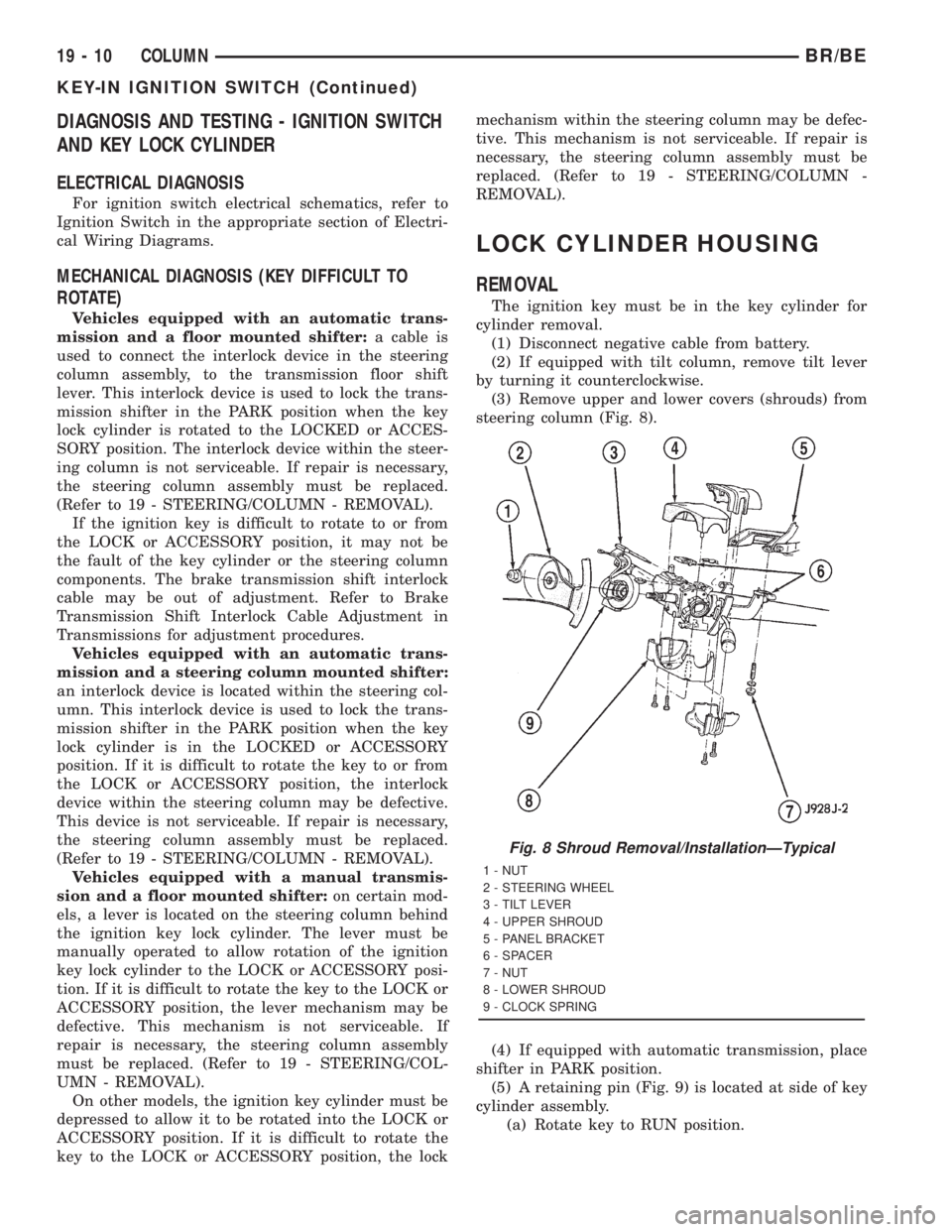
(3) Remove upper and lower covers (shrouds) from
steering column (Fig. 8).
(4) If equipped with automatic transmission, place
shifter in PARK position.
(5) A retaining pin (Fig. 9) is located at side of key
cylinder assembly.
(a) Rotate key to RUN position.
Fig. 8 Shroud Removal/InstallationÐTypical
1 - NUT
2 - STEERING WHEEL
3 - TILT LEVER
4 - UPPER SHROUD
5 - PANEL BRACKET
6 - SPACER
7 - NUT
8 - LOWER SHROUD
9 - CLOCK SPRING
19 - 10 COLUMNBR/BE
KEY-IN IGNITION SWITCH (Continued)
Page 1606 of 2889
GEAR SHIFT LEVER
REMOVAL
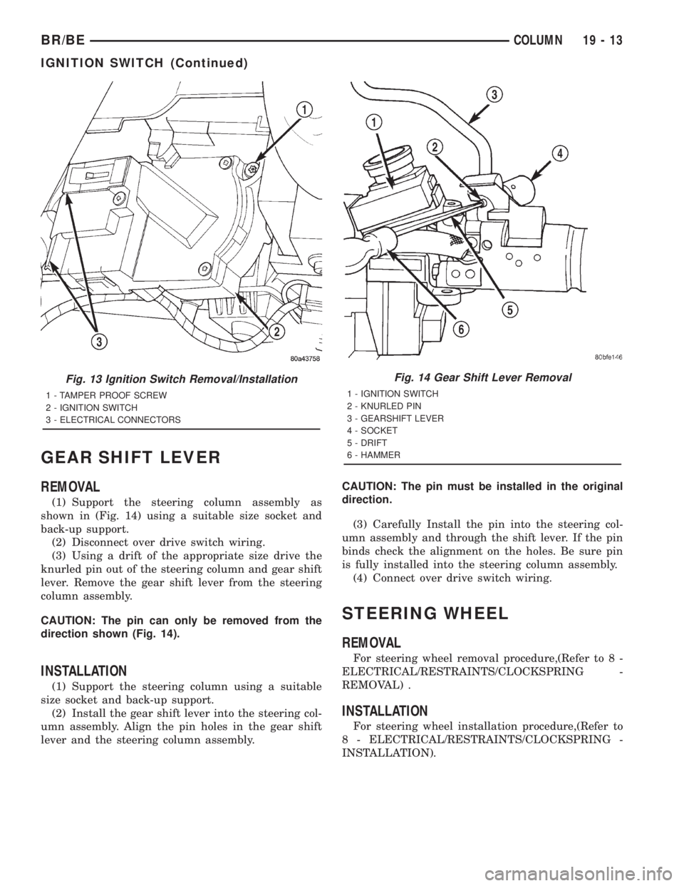
(1) Support the steering column assembly as
shown in (Fig. 14) using a suitable size socket and
back-up support.
(2) Disconnect over drive switch wiring.
(3) Using a drift of the appropriate size drive the
knurled pin out of the steering column and gear shift
lever. Remove the gear shift lever from the steering
column assembly.
CAUTION: The pin can only be removed from the
direction shown (Fig. 14).
INSTALLATION
(1) Support the steering column using a suitable
size socket and back-up support.
(2) Install the gear shift lever into the steering col-
umn assembly. Align the pin holes in the gear shift
lever and the steering column assembly.CAUTION: The pin must be installed in the original
direction.
(3) Carefully Install the pin into the steering col-
umn assembly and through the shift lever. If the pin
binds check the alignment on the holes. Be sure pin
is fully installed into the steering column assembly.
(4) Connect over drive switch wiring.
STEERING WHEEL
REMOVAL
For steering wheel removal procedure,(Refer to 8 -
ELECTRICAL/RESTRAINTS/CLOCKSPRING -
REMOVAL) .
INSTALLATION
For steering wheel installation procedure,(Refer to
8 - ELECTRICAL/RESTRAINTS/CLOCKSPRING -
INSTALLATION).
Fig. 13 Ignition Switch Removal/Installation
1 - TAMPER PROOF SCREW
2 - IGNITION SWITCH
3 - ELECTRICAL CONNECTORS
Fig. 14 Gear Shift Lever Removal
1 - IGNITION SWITCH
2 - KNURLED PIN
3 - GEARSHIFT LEVER
4 - SOCKET
5 - DRIFT
6 - HAMMER
BR/BECOLUMN 19 - 13
IGNITION SWITCH (Continued)
Page 1609 of 2889

REMOVAL
(1) Place the front wheels in a straight-ahead posi-
tion.
(2) Disconnect and cap the fluid hoses from steer-
ing gear.
(3) Remove coupler pinch bolt at the steering gear
and slide shaft off gear (Fig. 3).
(4) Mark the pitman shaft and pitman arm for
installation reference. Remove the pitman arm from
the shaft with Puller C-4150A (Fig. 4).(5) Remove steering gear retaining bolts and nuts.
Remove the steering gear from the vehicle.INSTALLATION
(1) Position the steering gear on the frame rail and
install the bolts. Tighten mounting bolts to specifica-
tions.
(2) Align steering coupler on gear shaft. Install
pinch bolt and tighten to 49 N´m (36 ft. lbs.) torque.
(3) Align and install the pitman arm.
(4) Install the washer and retaining nut on the pit-
man shaft. Tighten the nut to 251 N´m (185 ft. lbs.).
(5) Connect fluid hoses to steering gear, tighten to
31 N´m (23 ft. lbs.). Add fluid, (Refer to 19 - STEER-
ING/PUMP - STANDARD PROCEDURE).
ADJUSTMENTS
CAUTION: Steering gear must be adjusted in the
proper order. If adjustments are not performed in
order, gear damage and improper steering response
may result.
NOTE: Adjusting the steering gear in the vehicle is
not recommended. Remove gear from the vehicle
and drain the fluid. Then mount gear in a vise to
perform adjustments.
Fig. 2 STEERING GEAR
Fig. 3 Column Shaft
1 - STEERING GEAR
2 - STEERING COUPLER
Fig. 4 Pitman Arm
1 - PITMAN ARM
2 - SPECIAL TOOL C-4150-A
3 - WRENCH
19 - 16 GEARBR/BE
GEAR (Continued)
Page 1624 of 2889
PUMP
TABLE OF CONTENTS
page page
PUMP
DESCRIPTION...........................31
OPERATION.............................31
DIAGNOSIS AND TESTING.................31
PUMP LEAKAGE.......................31
STANDARD PROCEDURE..................31
POWER STEERING PUMP - INITIAL
OPERATION...........................31
FLUSHING POWER STEERING SYSTEM.....32
REMOVAL..............................33
INSTALLATION...........................35SPECIAL TOOLS.........................36
PULLEY
REMOVAL..............................36
INSTALLATION...........................36
HOSES - PRESSURE
DESCRIPTION...........................37
OPERATION.............................37
HOSES - RETURN
DESCRIPTION...........................37
OPERATION.............................37
PUMP
DESCRIPTION
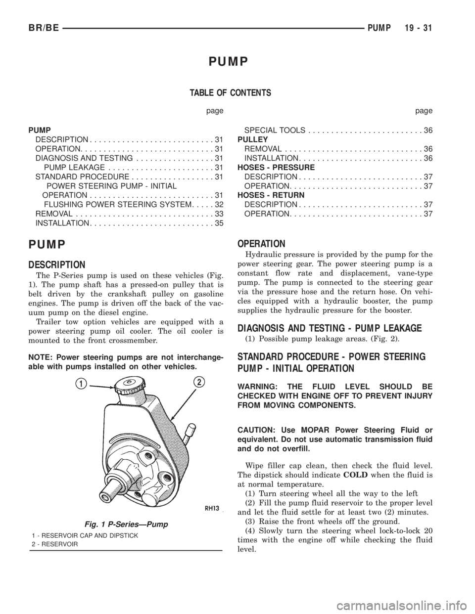
The P-Series pump is used on these vehicles (Fig.
1). The pump shaft has a pressed-on pulley that is
belt driven by the crankshaft pulley on gasoline
engines. The pump is driven off the back of the vac-
uum pump on the diesel engine.
Trailer tow option vehicles are equipped with a
power steering pump oil cooler. The oil cooler is
mounted to the front crossmember.
NOTE: Power steering pumps are not interchange-
able with pumps installed on other vehicles.
OPERATION
Hydraulic pressure is provided by the pump for the
power steering gear. The power steering pump is a
constant flow rate and displacement, vane-type
pump. The pump is connected to the steering gear
via the pressure hose and the return hose. On vehi-
cles equipped with a hydraulic booster, the pump
supplies the hydraulic pressure for the booster.
DIAGNOSIS AND TESTING - PUMP LEAKAGE
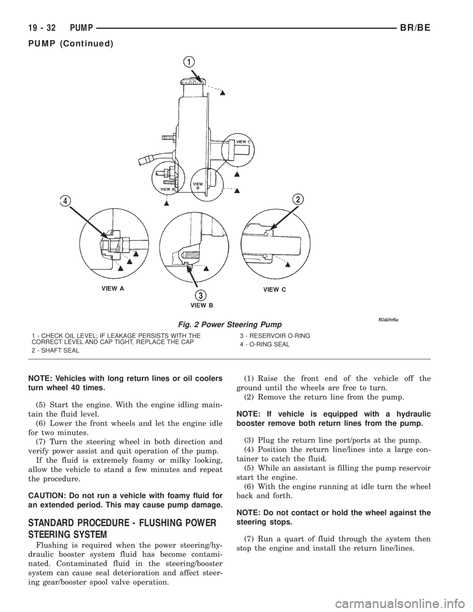
(1) Possible pump leakage areas. (Fig. 2).
STANDARD PROCEDURE - POWER STEERING
PUMP - INITIAL OPERATION
WARNING: THE FLUID LEVEL SHOULD BE
CHECKED WITH ENGINE OFF TO PREVENT INJURY
FROM MOVING COMPONENTS.
CAUTION: Use MOPAR Power Steering Fluid or
equivalent. Do not use automatic transmission fluid
and do not overfill.
Wipe filler cap clean, then check the fluid level.
The dipstick should indicateCOLDwhen the fluid is
at normal temperature.
(1) Turn steering wheel all the way to the left
(2) Fill the pump fluid reservoir to the proper level
and let the fluid settle for at least two (2) minutes.
(3) Raise the front wheels off the ground.
(4) Slowly turn the steering wheel lock-to-lock 20
times with the engine off while checking the fluid
level.
Fig. 1 P-SeriesÐPump
1 - RESERVOIR CAP AND DIPSTICK
2 - RESERVOIR
BR/BEPUMP 19 - 31
Page 1625 of 2889
NOTE: Vehicles with long return lines or oil coolers
turn wheel 40 times.
(5) Start the engine. With the engine idling main-
tain the fluid level.
(6) Lower the front wheels and let the engine idle
for two minutes.
(7) Turn the steering wheel in both direction and
verify power assist and quit operation of the pump.
If the fluid is extremely foamy or milky looking,
allow the vehicle to stand a few minutes and repeat
the procedure.
CAUTION: Do not run a vehicle with foamy fluid for
an extended period. This may cause pump damage.
STANDARD PROCEDURE - FLUSHING POWER
STEERING SYSTEM
Flushing is required when the power steering/hy-
draulic booster system fluid has become contami-
nated. Contaminated fluid in the steering/booster
system can cause seal deterioration and affect steer-
ing gear/booster spool valve operation.(1) Raise the front end of the vehicle off the
ground until the wheels are free to turn.
(2) Remove the return line from the pump.
NOTE: If vehicle is equipped with a hydraulic
booster remove both return lines from the pump.
(3) Plug the return line port/ports at the pump.
(4) Position the return line/lines into a large con-
tainer to catch the fluid.
(5) While an assistant is filling the pump reservoir
start the engine.
(6) With the engine running at idle turn the wheel
back and forth.
NOTE: Do not contact or hold the wheel against the
steering stops.
(7) Run a quart of fluid through the system then
stop the engine and install the return line/lines.
Fig. 2 Power Steering Pump
1 - CHECK OIL LEVEL; IF LEAKAGE PERSISTS WITH THE
CORRECT LEVEL AND CAP TIGHT, REPLACE THE CAP
2 - SHAFT SEAL3 - RESERVOIR O-RING
4 - O-RING SEAL
19 - 32 PUMPBR/BE
PUMP (Continued)
Page 1632 of 2889

INSTALLATION
(1) Position idler arm on the frame bracket and
tighten the bolt to specification.
(2) Center steering gear to alignment marks and
install pitman arm.
(3)
Install the lock washer and retaining nut on the
pitman shaft. Tighten the nut to 251 N´m (185 ft. lbs.).
(4) Install center link to ball studs and tighten
retaining nuts to specification.
(5) Install tie-rod ends into center link and tighten
the nuts to 88 N´m (65 ft. lbs.). Install new nuts.(6) Install tie-rod ends into steering knuckles and
tighten nuts to 108 N´m (80 ft. lbs.).
(7) Remove the supports and lower the vehicle to
the surface. Center steering wheel and adjust toe,
(Refer to 2 - SUSPENSION/WHEEL ALIGNMENT -
STANDARD PROCEDURE).
NOTE: Position the clamp on the sleeve so retain-
ing bolt is located on the bottom side of the sleeve.
(8) After adjustment, tighten the tie-rod adjust-
ment sleeve clamp bolt to 61 N´m (45 ft. lbs.).
SPECIFICATIONS
TORQUE CHART
TORQUE SPECIFICATIONS
DESCRIPTION N´m Ft. Lbs. In. Lbs.
Pitman Arm
Gear Nut250 185 Ð
Pitman Arm
Center Link Nut11 5 8 5 Ð
Idler Arm
Mounting Bolts271 200 Ð
Idler Arm
Center Link Nut88 65 Ð
Tie Rod
Knuckle Nut108 80 Ð
Tie Rod
Center Link Nut88 65 Ð
Tie Rod
Adjuster Clamp61 45 Ð
SPECIAL TOOLS
STEERING LINKAGE
Remover Ball Stud MB-991113
Puller Tie Rod C-3894-A
Remover Pitman C-4150A
BR/BELINKAGE - 2WD 19 - 39
LINKAGE - 2WD (Continued)