2001 DODGE RAM wheel
[x] Cancel search: wheelPage 1471 of 2889
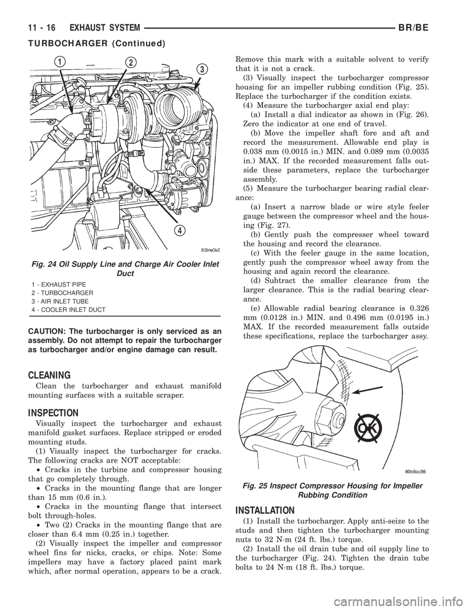
CAUTION: The turbocharger is only serviced as an
assembly. Do not attempt to repair the turbocharger
as turbocharger and/or engine damage can result.
CLEANING
Clean the turbocharger and exhaust manifold
mounting surfaces with a suitable scraper.
INSPECTION
Visually inspect the turbocharger and exhaust
manifold gasket surfaces. Replace stripped or eroded
mounting studs.
(1) Visually inspect the turbocharger for cracks.
The following cracks are NOT acceptable:
²Cracks in the turbine and compressor housing
that go completely through.
²Cracks in the mounting flange that are longer
than 15 mm (0.6 in.).
²Cracks in the mounting flange that intersect
bolt through-holes.
²Two (2) Cracks in the mounting flange that are
closer than 6.4 mm (0.25 in.) together.
(2) Visually inspect the impeller and compressor
wheel fins for nicks, cracks, or chips. Note: Some
impellers may have a factory placed paint mark
which, after normal operation, appears to be a crack.Remove this mark with a suitable solvent to verify
that it is not a crack.
(3) Visually inspect the turbocharger compressor
housing for an impeller rubbing condition (Fig. 25).
Replace the turbocharger if the condition exists.
(4) Measure the turbocharger axial end play:
(a) Install a dial indicator as shown in (Fig. 26).
Zero the indicator at one end of travel.
(b) Move the impeller shaft fore and aft and
record the measurement. Allowable end play is
0.038 mm (0.0015 in.) MIN. and 0.089 mm (0.0035
in.) MAX. If the recorded measurement falls out-
side these parameters, replace the turbocharger
assembly.
(5) Measure the turbocharger bearing radial clear-
ance:
(a) Insert a narrow blade or wire style feeler
gauge between the compressor wheel and the hous-
ing (Fig. 27).
(b) Gently push the compresser wheel toward
the housing and record the clearance.
(c) With the feeler gauge in the same location,
gently push the compressor wheel away from the
housing and again record the clearance.
(d) Subtract the smaller clearance from the
larger clearance. This is the radial bearing clear-
ance.
(e) Allowable radial bearing clearance is 0.326
mm (0.0128 in.) MIN. and 0.496 mm (0.0195 in.)
MAX. If the recorded measurement falls outside
these specifications, replace the turbocharger assy.
INSTALLATION
(1) Install the turbocharger. Apply anti-seize to the
studs and then tighten the turbocharger mounting
nuts to 32 N´m (24 ft. lbs.) torque.
(2) Install the oil drain tube and oil supply line to
the turbocharger (Fig. 24). Tighten the drain tube
bolts to 24 N´m (18 ft. lbs.) torque.
Fig. 24 Oil Supply Line and Charge Air Cooler Inlet
Duct
1 - EXHAUST PIPE
2 - TURBOCHARGER
3 - AIR INLET TUBE
4 - COOLER INLET DUCT
Fig. 25 Inspect Compressor Housing for Impeller
Rubbing Condition
11 - 16 EXHAUST SYSTEMBR/BE
TURBOCHARGER (Continued)
Page 1478 of 2889
FRONT LOWER FASCIA
REMOVAL
(1) Open hood.
(2) Remove fasteners at side fender openings.
(3) Remove lower air dam.(Refer to 13 - FRAMES
& BUMPERS/BUMPERS/FRONT AIR DAM -
REMOVAL)
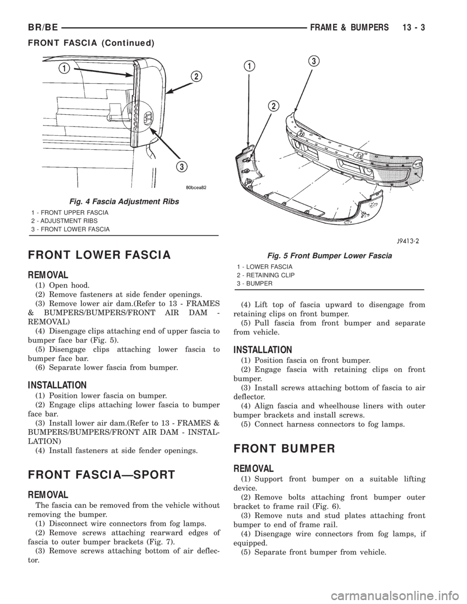
(4) Disengage clips attaching end of upper fascia to
bumper face bar (Fig. 5).
(5) Disengage clips attaching lower fascia to
bumper face bar.
(6) Separate lower fascia from bumper.
INSTALLATION
(1) Position lower fascia on bumper.
(2) Engage clips attaching lower fascia to bumper
face bar.
(3) Install lower air dam.(Refer to 13 - FRAMES &
BUMPERS/BUMPERS/FRONT AIR DAM - INSTAL-
LATION)
(4) Install fasteners at side fender openings.
FRONT FASCIAÐSPORT
REMOVAL
The fascia can be removed from the vehicle without
removing the bumper.
(1) Disconnect wire connectors from fog lamps.
(2) Remove screws attaching rearward edges of
fascia to outer bumper brackets (Fig. 7).
(3) Remove screws attaching bottom of air deflec-
tor.(4) Lift top of fascia upward to disengage from
retaining clips on front bumper.
(5) Pull fascia from front bumper and separate
from vehicle.
INSTALLATION
(1) Position fascia on front bumper.
(2) Engage fascia with retaining clips on front
bumper.
(3) Install screws attaching bottom of fascia to air
deflector.
(4) Align fascia and wheelhouse liners with outer
bumper brackets and install screws.
(5) Connect harness connectors to fog lamps.
FRONT BUMPER
REMOVAL
(1) Support front bumper on a suitable lifting
device.
(2) Remove bolts attaching front bumper outer
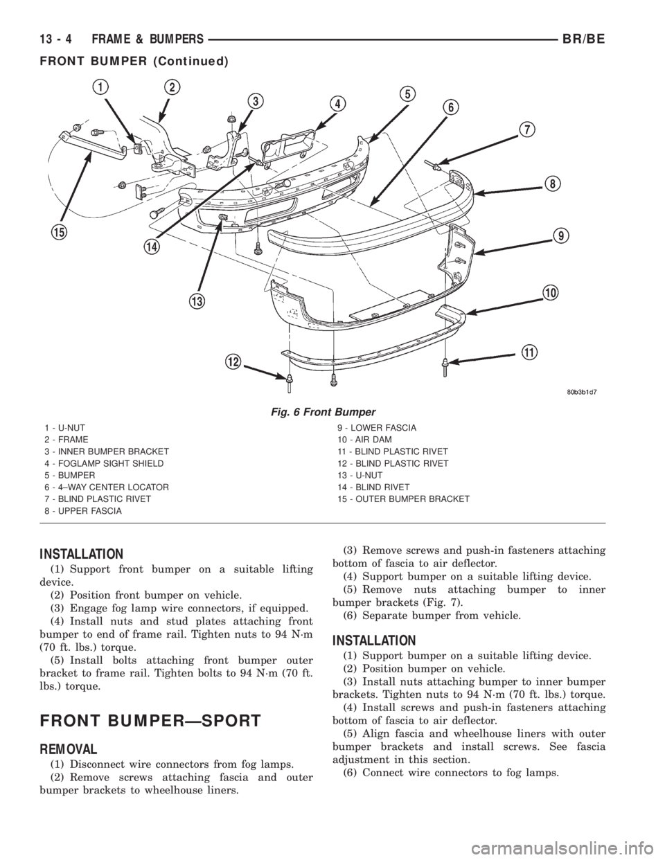
bracket to frame rail (Fig. 6).
(3) Remove nuts and stud plates attaching front
bumper to end of frame rail.
(4) Disengage wire connectors from fog lamps, if
equipped.
(5) Separate front bumper from vehicle.
Fig. 4 Fascia Adjustment Ribs
1 - FRONT UPPER FASCIA
2 - ADJUSTMENT RIBS
3 - FRONT LOWER FASCIA
Fig. 5 Front Bumper Lower Fascia
1 - LOWER FASCIA
2 - RETAINING CLIP
3 - BUMPER
BR/BEFRAME & BUMPERS 13 - 3
FRONT FASCIA (Continued)
Page 1479 of 2889
INSTALLATION
(1) Support front bumper on a suitable lifting
device.
(2) Position front bumper on vehicle.
(3) Engage fog lamp wire connectors, if equipped.
(4) Install nuts and stud plates attaching front
bumper to end of frame rail. Tighten nuts to 94 N´m
(70 ft. lbs.) torque.
(5) Install bolts attaching front bumper outer
bracket to frame rail. Tighten bolts to 94 N´m (70 ft.
lbs.) torque.
FRONT BUMPERÐSPORT
REMOVAL
(1) Disconnect wire connectors from fog lamps.
(2) Remove screws attaching fascia and outer
bumper brackets to wheelhouse liners.(3) Remove screws and push-in fasteners attaching
bottom of fascia to air deflector.
(4) Support bumper on a suitable lifting device.
(5) Remove nuts attaching bumper to inner
bumper brackets (Fig. 7).
(6) Separate bumper from vehicle.
INSTALLATION
(1) Support bumper on a suitable lifting device.
(2) Position bumper on vehicle.
(3) Install nuts attaching bumper to inner bumper
brackets. Tighten nuts to 94 N´m (70 ft. lbs.) torque.
(4) Install screws and push-in fasteners attaching
bottom of fascia to air deflector.
(5) Align fascia and wheelhouse liners with outer
bumper brackets and install screws. See fascia
adjustment in this section.
(6) Connect wire connectors to fog lamps.
Fig. 6 Front Bumper
1 - U-NUT
2 - FRAME
3 - INNER BUMPER BRACKET
4 - FOGLAMP SIGHT SHIELD
5 - BUMPER
6 - 4±WAY CENTER LOCATOR
7 - BLIND PLASTIC RIVET
8 - UPPER FASCIA9 - LOWER FASCIA
10 - AIR DAM
11 - BLIND PLASTIC RIVET
12 - BLIND PLASTIC RIVET
13 - U-NUT
14 - BLIND RIVET
15 - OUTER BUMPER BRACKET
13 - 4 FRAME & BUMPERSBR/BE
FRONT BUMPER (Continued)
Page 1482 of 2889
CAUTION: Do not reuse damaged fasteners, quality
of repair would be suspect. Do not drill holes in top
or bottom frame rail flanges, frame rail failure can
result. Do Not use softer than Grade 5 bolts to
replace production fasteners, loosening or failure
can result. When using heat to straighten frame
components do not exceed 566ÉC (1050ÉF), metal
fatigue can result. Welding the joints around riveted
cross members and frame side rails can weaken
frame.
FRAME STRAIGHTENING
When necessary, a conventional frame that is bent
or twisted can be straightened by application of heat.
The temperature must not exceed 566ÉC (1050ÉF).
The metal will have a dull red glow at the desired
temperature. Excessive heat will decrease the
strength of the metal and result in a weakened
frame.
Welding the joints around riveted cross members
and frame side rails is not recommended.
A straightening repair process should be limited to
frame members that are not severely damaged. The
replacement bolts, nuts and rivets that are used to
join the frame members should conform to the same
specifications as the original bolts, nuts and rivets.
FRAME REPAIRS
DRILLING HOLES
Do not drill holes in frame side rail top and bottom
flanges, metal fatigue can result causing frame fail-
ure. Holes drilled in the side of the frame rail must
be at least 38 mm (1.5 in.) from the top and bottom
flanges.
Additional drill holes should be located away from
existing holes.
WELDING
Use MIG, TIG or arc welding equipment to repair
welded frame components.
Frame components that have been damaged should
be inspected for cracks before returning the vehicle
to use. If cracks are found in accessible frame com-
ponents perform the following procedures.
(1) Drill a hole at each end of the crack with a 3
mm (O.125 in.) diameter drill bit.
(2) Using a suitable die grinder with 3 inch cut off
wheel, V-groove the crack to allow 100% weld pene-
tration.
(3) Weld the crack.(4) If necessary when a side rail is repaired, grind
the weld smooth and install a reinforcement channel
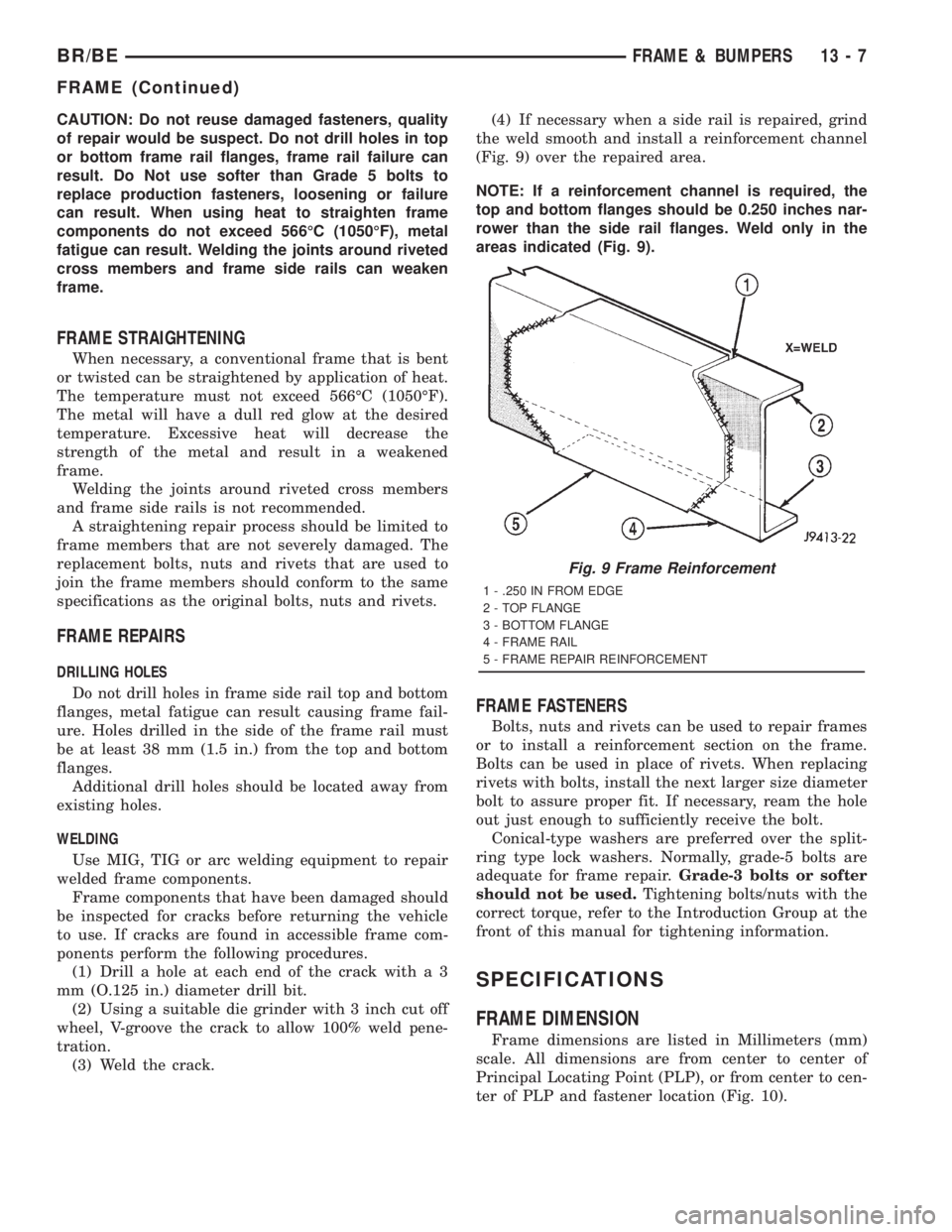
(Fig. 9) over the repaired area.
NOTE: If a reinforcement channel is required, the
top and bottom flanges should be 0.250 inches nar-
rower than the side rail flanges. Weld only in the
areas indicated (Fig. 9).
FRAME FASTENERS
Bolts, nuts and rivets can be used to repair frames
or to install a reinforcement section on the frame.
Bolts can be used in place of rivets. When replacing
rivets with bolts, install the next larger size diameter
bolt to assure proper fit. If necessary, ream the hole
out just enough to sufficiently receive the bolt.
Conical-type washers are preferred over the split-
ring type lock washers. Normally, grade-5 bolts are
adequate for frame repair.Grade-3 bolts or softer
should not be used.Tightening bolts/nuts with the
correct torque, refer to the Introduction Group at the
front of this manual for tightening information.
SPECIFICATIONS
FRAME DIMENSION
Frame dimensions are listed in Millimeters (mm)
scale. All dimensions are from center to center of
Principal Locating Point (PLP), or from center to cen-
ter of PLP and fastener location (Fig. 10).
Fig. 9 Frame Reinforcement
1 - .250 IN FROM EDGE
2 - TOP FLANGE
3 - BOTTOM FLANGE
4 - FRAME RAIL
5 - FRAME REPAIR REINFORCEMENT
BR/BEFRAME & BUMPERS 13 - 7
FRAME (Continued)
Page 1484 of 2889
DIMENSIONS FOR DIFFERING WHEELBASES*
WHEELBASE LENGTH
ALENGTH
BLENGTH
C
118 2118.0 3663.6 4185.4
134 2118.0 3994.5 4693.4
138 2626.0 4096.1 4693.4
154 2626.0 4502.5 5201.4
162 2118.0 4705.0 5042.5
*Measurements are in Millimeters (mm).
TORQUE SPECIFICATIONS
DESCRIPTION TORQUE
Cab Chassis adapter nut..... 108N´m(80ft.lbs.)
Front bumper brkt-to-frame nut . 68 N´m (50 ft. lbs.)
Front bumper outer brace bolt . . 68 N´m (50 ft. lbs.)
Rear bumper-to-brace nut..... 40N´m(30ft.lbs.)
Rear bumper brace-to-brkt nut . 101 N´m (75 ft. lbs.)
Rear bumper brkt-to-frame nut......... 101N´m
(75 ft. lbs.)
Skid plate crossmember-to-frame bolt..... 54N´m
(40 ft. lbs.)
Skid plate-to-crossmember bolt . 40 N´m (30 ft. lbs.)
Skid plate-to-trans crossmember bolt...... 54N´m
(40 ft. lbs.)
Spare tire winch bolt......... 27N´m(20ft.lbs.)
Trailer hitch nut............ 108N´m(80ft.lbs.)
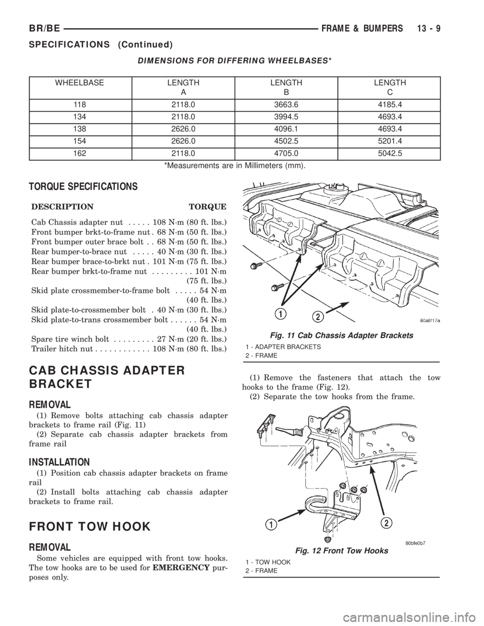
CAB CHASSIS ADAPTER
BRACKET
REMOVAL
(1) Remove bolts attaching cab chassis adapter
brackets to frame rail (Fig. 11)
(2) Separate cab chassis adapter brackets from
frame rail
INSTALLATION
(1) Position cab chassis adapter brackets on frame
rail
(2) Install bolts attaching cab chassis adapter
brackets to frame rail.
FRONT TOW HOOK
REMOVAL
Some vehicles are equipped with front tow hooks.
The tow hooks are to be used forEMERGENCYpur-
poses only.(1) Remove the fasteners that attach the tow
hooks to the frame (Fig. 12).
(2) Separate the tow hooks from the frame.
Fig. 11 Cab Chassis Adapter Brackets
1 - ADAPTER BRACKETS
2 - FRAME
Fig. 12 Front Tow Hooks
1 - TOW HOOK
2 - FRAME
BR/BEFRAME & BUMPERS 13 - 9
SPECIFICATIONS (Continued)
Page 1507 of 2889
(6)Open fuel fill door and remove screws mounting
fuel filler tube assembly to body. Do not disconnect
rubber fuel fill or vent hoses from tank at this time.
(7) Place a transmission jack under center of fuel
tank. Apply a slight amount of pressure to fuel tank
with transmission jack.
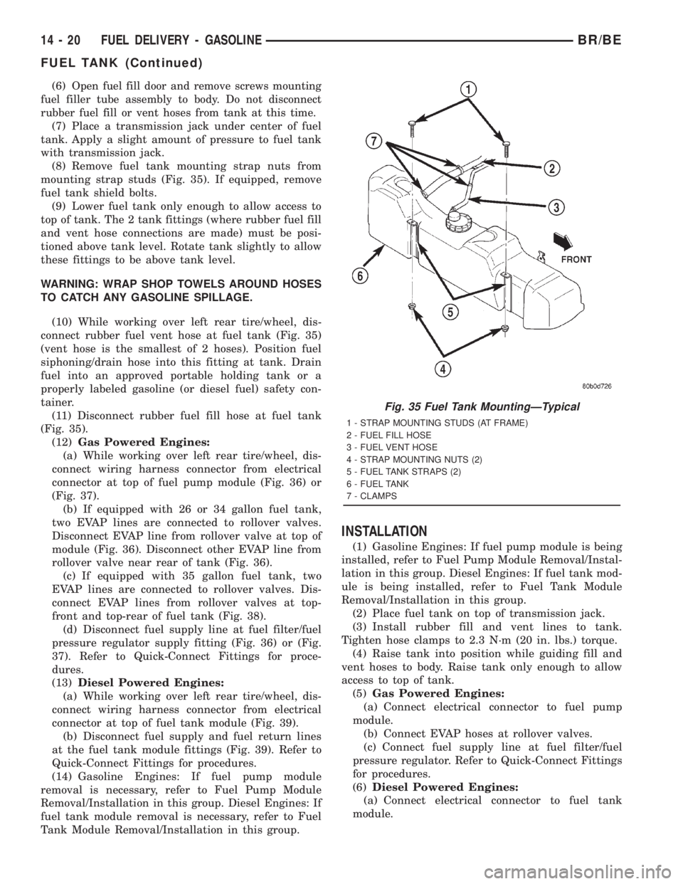
(8) Remove fuel tank mounting strap nuts from
mounting strap studs (Fig. 35). If equipped, remove
fuel tank shield bolts.
(9) Lower fuel tank only enough to allow access to
top of tank. The 2 tank fittings (where rubber fuel fill
and vent hose connections are made) must be posi-
tioned above tank level. Rotate tank slightly to allow
these fittings to be above tank level.
WARNING: WRAP SHOP TOWELS AROUND HOSES
TO CATCH ANY GASOLINE SPILLAGE.
(10) While working over left rear tire/wheel, dis-
connect rubber fuel vent hose at fuel tank (Fig. 35)
(vent hose is the smallest of 2 hoses). Position fuel
siphoning/drain hose into this fitting at tank. Drain
fuel into an approved portable holding tank or a
properly labeled gasoline (or diesel fuel) safety con-
tainer.
(11) Disconnect rubber fuel fill hose at fuel tank
(Fig. 35).
(12)Gas Powered Engines:
(a) While working over left rear tire/wheel, dis-
connect wiring harness connector from electrical
connector at top of fuel pump module (Fig. 36) or
(Fig. 37).
(b) If equipped with 26 or 34 gallon fuel tank,
two EVAP lines are connected to rollover valves.
Disconnect EVAP line from rollover valve at top of
module (Fig. 36). Disconnect other EVAP line from
rollover valve near rear of tank (Fig. 36).
(c) If equipped with 35 gallon fuel tank, two
EVAP lines are connected to rollover valves. Dis-
connect EVAP lines from rollover valves at top-
front and top-rear of fuel tank (Fig. 38).
(d) Disconnect fuel supply line at fuel filter/fuel
pressure regulator supply fitting (Fig. 36) or (Fig.
37). Refer to Quick-Connect Fittings for proce-
dures.
(13)Diesel Powered Engines:
(a) While working over left rear tire/wheel, dis-
connect wiring harness connector from electrical
connector at top of fuel tank module (Fig. 39).
(b) Disconnect fuel supply and fuel return lines
at the fuel tank module fittings (Fig. 39). Refer to
Quick-Connect Fittings for procedures.
(14) Gasoline Engines: If fuel pump module
removal is necessary, refer to Fuel Pump Module
Removal/Installation in this group. Diesel Engines: If
fuel tank module removal is necessary, refer to Fuel
Tank Module Removal/Installation in this group.
INSTALLATION
(1) Gasoline Engines: If fuel pump module is being
installed, refer to Fuel Pump Module Removal/Instal-
lation in this group. Diesel Engines: If fuel tank mod-
ule is being installed, refer to Fuel Tank Module
Removal/Installation in this group.
(2) Place fuel tank on top of transmission jack.
(3) Install rubber fill and vent lines to tank.
Tighten hose clamps to 2.3 N´m (20 in. lbs.) torque.
(4) Raise tank into position while guiding fill and
vent hoses to body. Raise tank only enough to allow
access to top of tank.
(5)Gas Powered Engines:
(a) Connect electrical connector to fuel pump
module.
(b) Connect EVAP hoses at rollover valves.
(c) Connect fuel supply line at fuel filter/fuel
pressure regulator. Refer to Quick-Connect Fittings
for procedures.
(6)Diesel Powered Engines:
(a) Connect electrical connector to fuel tank
module.
Fig. 35 Fuel Tank MountingÐTypical
1 - STRAP MOUNTING STUDS (AT FRAME)
2 - FUEL FILL HOSE
3 - FUEL VENT HOSE
4 - STRAP MOUNTING NUTS (2)
5 - FUEL TANK STRAPS (2)
6 - FUEL TANK
7 - CLAMPS
14 - 20 FUEL DELIVERY - GASOLINEBR/BE
FUEL TANK (Continued)
Page 1518 of 2889
(23) Inspect for exhaust system restrictions such
as pinched exhaust pipes, collapsed muffler or
plugged catalytic convertor.
(24) If equipped with automatic transmission, ver-
ify that electrical harness is firmly connected to park/
neutral switch. Refer to 21, Automatic Transmission.
(25) Verify electrical harness is firmly connected to
rear wheel speed sensor. Verify rear wheel speed sen-sor is firmly attached to rear axle with proper air
gap. Refer to 5, Brakes for information.
(26) If equipped with 4±wheel antilock brake sys-
tem, verify electrical harness is firmly connected to
each front wheel speed sensor. Verify both front
wheel speed sensors are firmly attached. Refer to 5,
Brakes for information.
(27) Verify that fuel pump/gauge sender unit wire
connector is firmly connected to harness connector.
(28) Inspect fuel hoses at fuel pump/gauge sender
unit for cracks or leaks.
(29) Inspect transmission torque convertor housing
(automatic transmission) or clutch housing (manual
transmission) for damage to timing ring on drive
plate/flywheel.
(30) Verify that battery cable and solenoid feed
wire connections to the starter solenoid are tight and
clean. Inspect for chaffed wires or wires rubbing up
against other components.
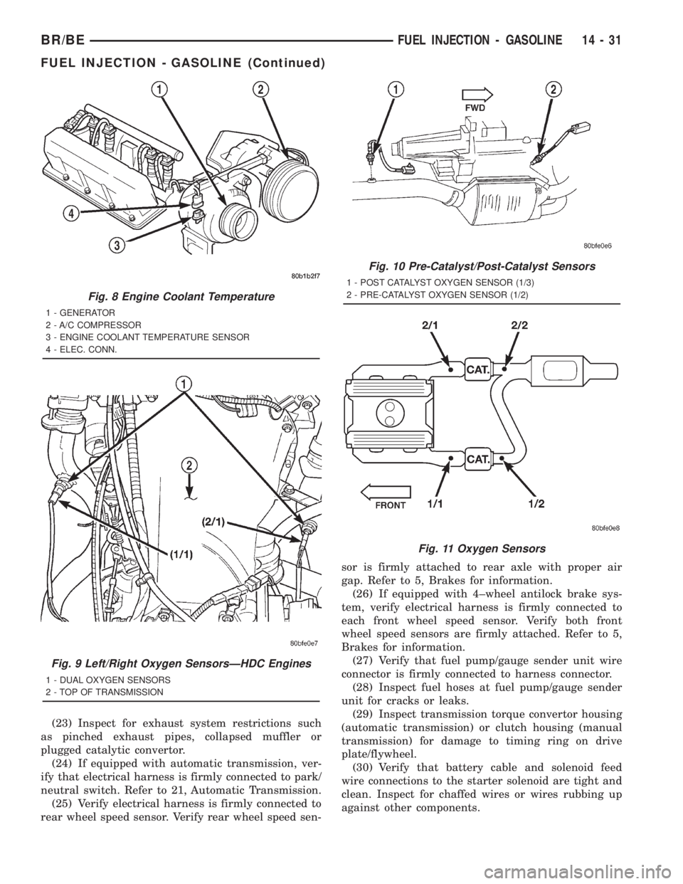
Fig. 8 Engine Coolant Temperature
1 - GENERATOR
2 - A/C COMPRESSOR
3 - ENGINE COOLANT TEMPERATURE SENSOR
4 - ELEC. CONN.
Fig. 9 Left/Right Oxygen SensorsÐHDC Engines
1 - DUAL OXYGEN SENSORS
2 - TOP OF TRANSMISSION
Fig. 10 Pre-Catalyst/Post-Catalyst Sensors
1 - POST CATALYST OXYGEN SENSOR (1/3)
2 - PRE-CATALYST OXYGEN SENSOR (1/2)
Fig. 11 Oxygen Sensors
BR/BEFUEL INJECTION - GASOLINE 14 - 31
FUEL INJECTION - GASOLINE (Continued)
Page 1521 of 2889
(25) Verify electrical harness is firmly connected to
rear wheel speed sensor. Verify rear wheel speed sen-
sor is firmly attached to rear axle with proper air
gap. Refer to 5, Brakes for information.
(26) If equipped with 4±wheel antilock brake sys-
tem, verify electrical harness is firmly connected to
each front wheel speed sensor. Verify both front
wheel speed sensors are firmly attached. Refer to 5,
Brakes for information.
(27) Verify that fuel pump/gauge sender unit wire
connector is firmly connected to harness connector.
(28) Inspect fuel hoses at fuel pump/gauge sender
unit for cracks or leaks.
(29) Inspect transmission torque convertor housing
(automatic transmission) or clutch housing (manual
transmission) for damage to timing ring on drive
plate/flywheel.
(30) Verify that battery cable and solenoid feed
wire connections to the starter solenoid are tight and
clean. Inspect for chaffed wires or wires rubbing up
against other components.
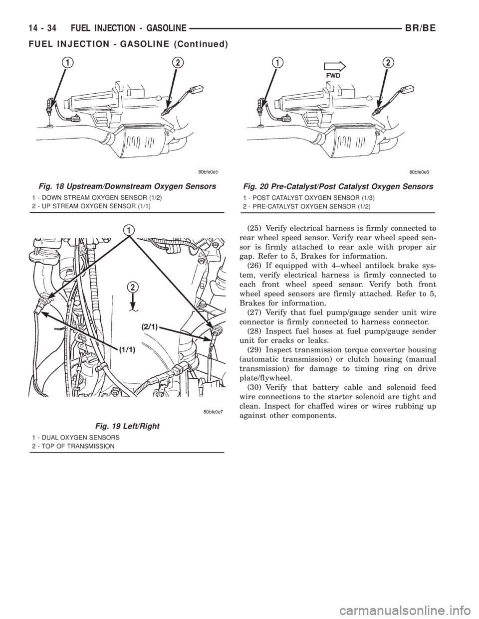
Fig. 18 Upstream/Downstream Oxygen Sensors
1 - DOWN STREAM OXYGEN SENSOR (1/2)
2 - UP STREAM OXYGEN SENSOR (1/1)
Fig. 19 Left/Right
1 - DUAL OXYGEN SENSORS
2 - TOP OF TRANSMISSION
Fig. 20 Pre-Catalyst/Post Catalyst Oxygen Sensors
1 - POST CATALYST OXYGEN SENSOR (1/3)
2 - PRE-CATALYST OXYGEN SENSOR (1/2)
14 - 34 FUEL INJECTION - GASOLINEBR/BE
FUEL INJECTION - GASOLINE (Continued)