2001 DODGE RAM wheel
[x] Cancel search: wheelPage 1525 of 2889
CRANKSHAFT POSITION
SENSOR
DESCRIPTION - 3.9L
The Crankshaft Position (CKP) sensor is located
near the outer edge of the flywheel (starter ringear).
DESCRIPTION - 5.2L/5.9L
The Crankshaft Position (CKP) sensor is located
near the outer edge of the flywheel (starter ringear).
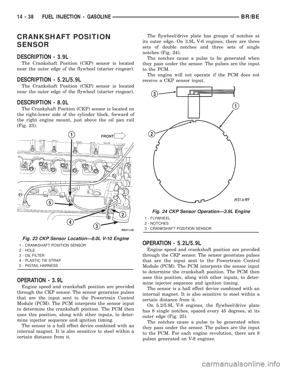
DESCRIPTION - 8.0L
The Crankshaft Position (CKP) sensor is located on
the right-lower side of the cylinder block, forward of
the right engine mount, just above the oil pan rail
(Fig. 23).
OPERATION - 3.9L
Engine speed and crankshaft position are provided
through the CKP sensor. The sensor generates pulses
that are the input sent to the Powertrain Control
Module (PCM). The PCM interprets the sensor input
to determine the crankshaft position. The PCM then
uses this position, along with other inputs, to deter-
mine injector sequence and ignition timing.
The sensor is a hall effect device combined with an
internal magnet. It is also sensitive to steel within a
certain distance from it.The flywheel/drive plate has groups of notches at
its outer edge. On 3.9L V-6 engines, there are three
sets of double notches and three sets of single
notches (Fig. 24).
The notches cause a pulse to be generated when
they pass under the sensor. The pulses are the input
to the PCM.
The engine will not operate if the PCM does not
receive a CKP sensor input.
OPERATION - 5.2L/5.9L
Engine speed and crankshaft position are provided
through the CKP sensor. The sensor generates pulses
that are the input sent to the Powertrain Control
Module (PCM). The PCM interprets the sensor input
to determine the crankshaft position. The PCM then
uses this position, along with other inputs, to deter-
mine injector sequence and ignition timing.
The sensor is a hall effect device combined with an
internal magnet. It is also sensitive to steel within a
certain distance from it.
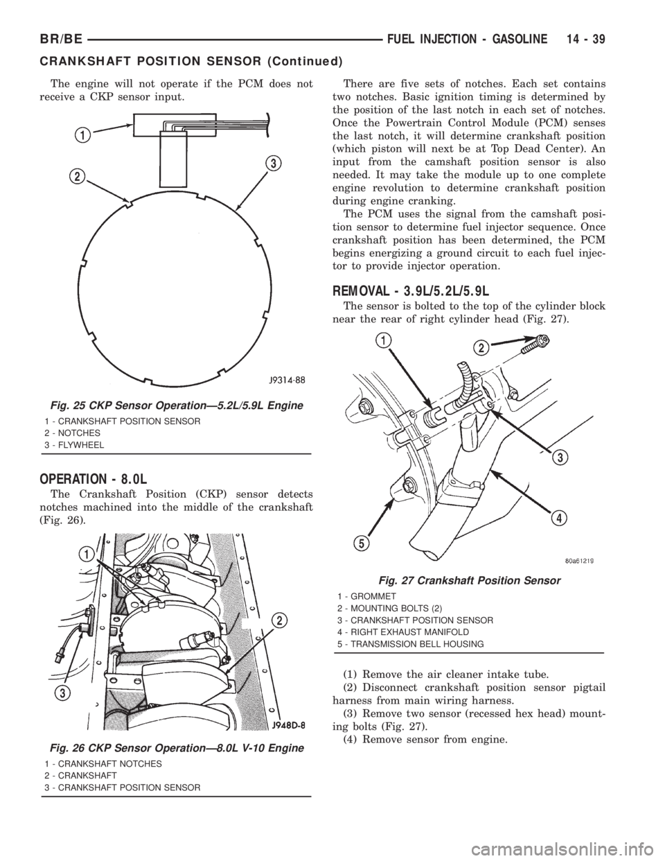
On 5.2/5.9L V-8 engines, the flywheel/drive plate
has 8 single notches, spaced every 45 degrees, at its
outer edge (Fig. 25).
The notches cause a pulse to be generated when
they pass under the sensor. The pulses are the input
to the PCM. For each engine revolution, there are 8
pulses generated on V-8 engines.
Fig. 23 CKP Sensor LocationÐ8.0L V-10 Engine
1 - CRANKSHAFT POSITION SENSOR
2 - HOLE
3 - OIL FILTER
4 - PLASTIC TIE STRAP
5 - PIGTAIL HARNESS
Fig. 24 CKP Sensor OperationÐ3.9L Engine
1 - FLYWHEEL
2 - NOTCHES
3 - CRANKSHAFT POSITION SENSOR
14 - 38 FUEL INJECTION - GASOLINEBR/BE
Page 1526 of 2889
The engine will not operate if the PCM does not
receive a CKP sensor input.
OPERATION - 8.0L
The Crankshaft Position (CKP) sensor detects
notches machined into the middle of the crankshaft
(Fig. 26).There are five sets of notches. Each set contains
two notches. Basic ignition timing is determined by
the position of the last notch in each set of notches.
Once the Powertrain Control Module (PCM) senses
the last notch, it will determine crankshaft position
(which piston will next be at Top Dead Center). An
input from the camshaft position sensor is also
needed. It may take the module up to one complete
engine revolution to determine crankshaft position
during engine cranking.
The PCM uses the signal from the camshaft posi-
tion sensor to determine fuel injector sequence. Once
crankshaft position has been determined, the PCM
begins energizing a ground circuit to each fuel injec-
tor to provide injector operation.
REMOVAL - 3.9L/5.2L/5.9L
The sensor is bolted to the top of the cylinder block
near the rear of right cylinder head (Fig. 27).
(1) Remove the air cleaner intake tube.
(2) Disconnect crankshaft position sensor pigtail
harness from main wiring harness.
(3) Remove two sensor (recessed hex head) mount-
ing bolts (Fig. 27).
(4) Remove sensor from engine.
Fig. 25 CKP Sensor OperationÐ5.2L/5.9L Engine
1 - CRANKSHAFT POSITION SENSOR
2 - NOTCHES
3 - FLYWHEEL
Fig. 26 CKP Sensor OperationÐ8.0L V-10 Engine
1 - CRANKSHAFT NOTCHES
2 - CRANKSHAFT
3 - CRANKSHAFT POSITION SENSOR
Fig. 27 Crankshaft Position Sensor
1 - GROMMET
2 - MOUNTING BOLTS (2)
3 - CRANKSHAFT POSITION SENSOR
4 - RIGHT EXHAUST MANIFOLD
5 - TRANSMISSION BELL HOUSING
BR/BEFUEL INJECTION - GASOLINE 14 - 39
CRANKSHAFT POSITION SENSOR (Continued)
Page 1557 of 2889
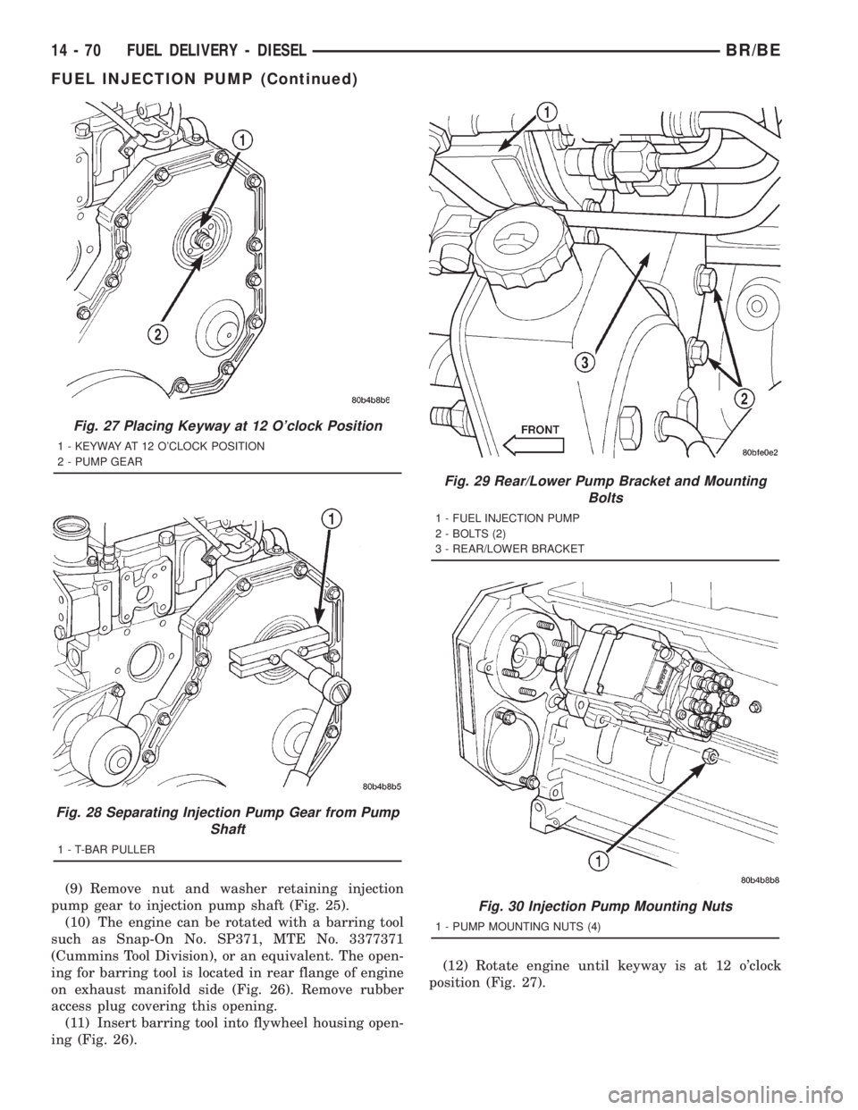
(9) Remove nut and washer retaining injection
pump gear to injection pump shaft (Fig. 25).
(10) The engine can be rotated with a barring tool
such as Snap-On No. SP371, MTE No. 3377371
(Cummins Tool Division), or an equivalent. The open-
ing for barring tool is located in rear flange of engine
on exhaust manifold side (Fig. 26). Remove rubber
access plug covering this opening.
(11) Insert barring tool into flywheel housing open-
ing (Fig. 26).(12) Rotate engine until keyway is at 12 o'clock
position (Fig. 27).
Fig. 27 Placing Keyway at 12 O'clock Position
1 - KEYWAY AT 12 O'CLOCK POSITION
2 - PUMP GEAR
Fig. 28 Separating Injection Pump Gear from Pump
Shaft
1 - T-BAR PULLER
Fig. 29 Rear/Lower Pump Bracket and Mounting
Bolts
1 - FUEL INJECTION PUMP
2 - BOLTS (2)
3 - REAR/LOWER BRACKET
Fig. 30 Injection Pump Mounting Nuts
1 - PUMP MOUNTING NUTS (4)
14 - 70 FUEL DELIVERY - DIESELBR/BE
FUEL INJECTION PUMP (Continued)
Page 1595 of 2889

DIAGNOSIS AND TESTING - POWER STEERING SYSTEM
There is some noise in all power steering systems. One of the most common is a hissing sound evident at a
standstill parking. Or when the steering wheel is at the end of it's travel. Hiss is a high frequency noise similar
to that of a water tap being closed slowly. The noise is present in all valves that have a high velocity fluid passing
through an orifice. There is no relationship between this noise and steering performance.
STEERING NOISE
CONDITION POSSIBLE CAUSES CORRECTION
OBJECTIONAL HISS OR
WHISTLE1. Steering intermediate shaft to dash panel
seal.1. Check and repair seal at dash
panel.
2. Noisy valve in power steering gear. 2. Repair steering gear.
RATTLE OR CLUNK 1. Gear mounting bolts loose. 1. Tighten bolts to specification.
2. Loose or damaged suspension
components.2. Inspect and repair suspension.
3. Loose or damaged steering linkage. 3. Inspect and repair steering
linkage.
4. Internal gear noise. 4. Repair steering gear.
5. Pressure hose in contact with other
components.5. Reposition hose.
6. Loose or damaged intermediate shaft or
column.6. Inspect and repair or replace.
CHIRP OR SQUEAL 1. Loose belt. 1. Adjust or replace.
WHINE OR GROWL 1. Low fluid level. 1. Fill to proper level.
2. Pressure hose in contact with other
components.2. Reposition hose.
3. Internal pump noise. 3. Replace pump.
SUCKING AIR SOUND 1. Loose return line clamp. 1. Replace clamp.
2. O-ring missing or damaged on hose
fitting.2. Replace o-ring.
3. Low fluid level. 3. Fill to proper level.
4. Air leak between pump and reservoir. 4. Repair as necessary.
5. Reservoir cap not installed correctly. 5. Install reservoir cap correctly.
SCRUBBING OR
KNOCKING1. Wrong tire size. 1. Verify tire size.
2. Wrong gear. 2. Verify gear.
19 - 2 STEERINGBR/BE
STEERING (Continued)
Page 1596 of 2889

BINDING AND STICKING
CONDITION POSSIBLE CAUSE CORRECTION
DIFFICULT TO TURN WHEEL
STICKS OR BINDS1. Low fluid level. 1. Fill to proper level.
2. Tire pressure. 2. Adjust tire pressure.
3. Steering components (ball
joints/tie rod ends).3. Lube, inspect and repair as
necessary.
4. Loose belt. 4. Adjust or replace.
5. Low pump pressure. 5. Pressure test and replace if
necessary.
6. Column shaft coupler binding. 6. Replace coupler.
7. Steering gear worn or out of
adjustment.7. Repair or replace gear.
INSUFFICIENT ASST. OR POOR RETURN TO CENTER
CONDITION POSSIBLE CAUSE CORRECTION
HARD TURNING OR MOMENTARY
INCREASE IN TURNING EFFORT1. Tire pressure. 1. Adjust tire pressure.
2. Low fluid level. 2. Fill to proper level.
3. Loose belt. 3. Adjust or replace.
4. Lack of lubrication. 4. Inspect and lubricate steering and
suspension compnents.
5. Low pump pressure. 5. Pressure test and repair as
necessary.
6. Internal gear leak. 6. Pressure and flow test, and repair
as necessary.
STEERING WHEEL DOES NOT
WANT TO RETURN TO CENTER
POSITION1. Tire pressure. 1. Adjust tire pressure.
2. Wheel alignment. 2. Align front end.
3. Lack of lubrication. 3. Inspect and lubricate steering and
suspension compnents.
4. High friction in steering gear. 4. Test and adjust gear as
necessary.
LOOSE STEERING AND VEHICLE LEAD
CONDITION POSSIBLE CAUSE CORRECTION
EXCESSIVE PLAY IN STEERING
WHEEL1. Worn or loose suspension or
steering components.1. Inspect and repair as necessary.
2. Worn or loose wheel bearings. 2. Inspect and repair or adjust
bearings.
3. Steering gear mounting. 3. Tighten gear mounting bolts to
specification.
4. Gear out of adjustment. 4. Adjust gear to specification.
5. Worn or loose steering coupler. 5. Inspect and replace as
necessary.
BR/BESTEERING 19 - 3
STEERING (Continued)
Page 1597 of 2889
CONDITION POSSIBLE CAUSE CORRECTION
VEHICLE PULLS OR LEADS TO
ONE SIDE.1. Tire Pressure. 1. Adjust tire pressure.
2. Radial tire lead. 2. Rotate tires.
3. Brakes dragging. 3. Repair as necessary.
4. Wheel alignment. 4. Align front end.
DIAGNOSIS AND TESTING - POWER STEERING
FLOW AND PRESSURE
The following procedure is used to test the opera-
tion of the power steering system on the vehicle. This
test will provide the flow rate of the power steering
pump along with the maximum relief pressure. Per-
form test any time a power steering system problem
is present. This test will determine if the power
steering pump or power steering gear is not function-
ing properly. The following pressure and flow test is
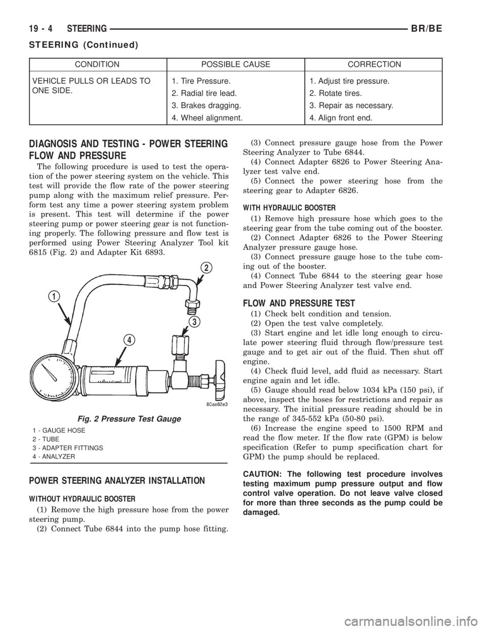
performed using Power Steering Analyzer Tool kit
6815 (Fig. 2) and Adapter Kit 6893.
POWER STEERING ANALYZER INSTALLATION
WITHOUT HYDRAULIC BOOSTER
(1) Remove the high pressure hose from the power
steering pump.
(2) Connect Tube 6844 into the pump hose fitting.(3) Connect pressure gauge hose from the Power
Steering Analyzer to Tube 6844.
(4) Connect Adapter 6826 to Power Steering Ana-
lyzer test valve end.
(5) Connect the power steering hose from the
steering gear to Adapter 6826.
WITH HYDRAULIC BOOSTER
(1) Remove high pressure hose which goes to the
steering gear from the tube coming out of the booster.
(2) Connect Adapter 6826 to the Power Steering
Analyzer pressure gauge hose.
(3) Connect pressure gauge hose to the tube com-
ing out of the booster.
(4) Connect Tube 6844 to the steering gear hose
and Power Steering Analyzer test valve end.
FLOW AND PRESSURE TEST
(1) Check belt condition and tension.
(2) Open the test valve completely.
(3) Start engine and let idle long enough to circu-
late power steering fluid through flow/pressure test
gauge and to get air out of the fluid. Then shut off
engine.
(4) Check fluid level, add fluid as necessary. Start
engine again and let idle.
(5) Gauge should read below 1034 kPa (150 psi), if
above, inspect the hoses for restrictions and repair as
necessary. The initial pressure reading should be in
the range of 345-552 kPa (50-80 psi).
(6) Increase the engine speed to 1500 RPM and
read the flow meter. If the flow rate (GPM) is below
specification (Refer to pump specification chart for
GPM) the pump should be replaced.
CAUTION: The following test procedure involves
testing maximum pump pressure output and flow
control valve operation. Do not leave valve closed
for more than three seconds as the pump could be
damaged.
Fig. 2 Pressure Test Gauge
1 - GAUGE HOSE
2 - TUBE
3 - ADAPTER FITTINGS
4 - ANALYZER
19 - 4 STEERINGBR/BE
STEERING (Continued)
Page 1598 of 2889
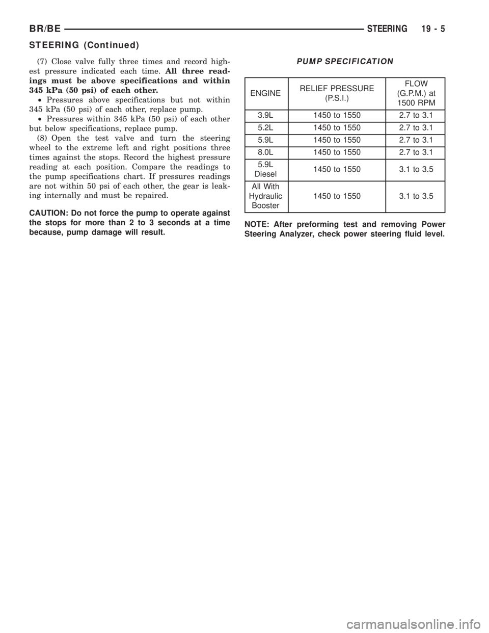
(7) Close valve fully three times and record high-
est pressure indicated each time.All three read-
ings must be above specifications and within
345 kPa (50 psi) of each other.
²Pressures above specifications but not within
345 kPa (50 psi) of each other, replace pump.
²Pressures within 345 kPa (50 psi) of each other
but below specifications, replace pump.
(8) Open the test valve and turn the steering
wheel to the extreme left and right positions three
times against the stops. Record the highest pressure
reading at each position. Compare the readings to
the pump specifications chart. If pressures readings
are not within 50 psi of each other, the gear is leak-
ing internally and must be repaired.
CAUTION: Do not force the pump to operate against
the stops for more than 2 to 3 seconds at a time
because, pump damage will result.PUMP SPECIFICATION
ENGINERELIEF PRESSURE
(P.S.I.)FLOW
(G.P.M.) at
1500 RPM
3.9L 1450 to 1550 2.7 to 3.1
5.2L 1450 to 1550 2.7 to 3.1
5.9L 1450 to 1550 2.7 to 3.1
8.0L 1450 to 1550 2.7 to 3.1
5.9L
Diesel1450 to 1550 3.1 to 3.5
All With
Hydraulic
Booster1450 to 1550 3.1 to 3.5
NOTE: After preforming test and removing Power
Steering Analyzer, check power steering fluid level.
BR/BESTEERING 19 - 5
STEERING (Continued)
Page 1599 of 2889
COLUMN
TABLE OF CONTENTS
page page
COLUMN
DESCRIPTION............................6
OPERATION.............................6
REMOVAL...............................7
INSTALLATION............................8
SPECIFICATIONS.........................9
KEY-IN IGNITION SWITCH
DESCRIPTION............................9
DIAGNOSIS AND TESTING.................10
IGNITION SWITCH AND KEY LOCK
CYLINDER............................10
LOCK CYLINDER HOUSING
REMOVAL..............................10
INSTALLATION...........................11IGNITION SWITCH
DESCRIPTION...........................11
OPERATION.............................11
DIAGNOSIS AND TESTING.................11
IGNITION SWITCH......................11
REMOVAL..............................12
INSTALLATION...........................12
GEAR SHIFT LEVER
REMOVAL..............................13
INSTALLATION...........................13
STEERING WHEEL
REMOVAL..............................13
INSTALLATION...........................13
COLUMN
DESCRIPTION
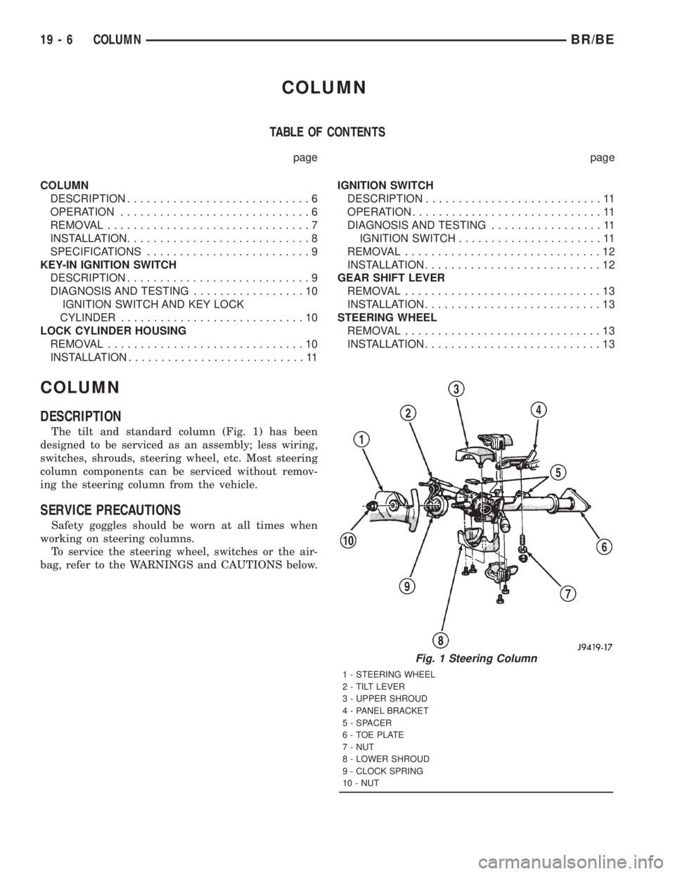
The tilt and standard column (Fig. 1) has been
designed to be serviced as an assembly; less wiring,
switches, shrouds, steering wheel, etc. Most steering
column components can be serviced without remov-
ing the steering column from the vehicle.
SERVICE PRECAUTIONS
Safety goggles should be worn at all times when
working on steering columns.
To service the steering wheel, switches or the air-
bag, refer to the WARNINGS and CAUTIONS below.
Fig. 1 Steering Column
1 - STEERING WHEEL
2 - TILT LEVER
3 - UPPER SHROUD
4 - PANEL BRACKET
5 - SPACER
6 - TOE PLATE
7 - NUT
8 - LOWER SHROUD
9 - CLOCK SPRING
10 - NUT
19 - 6 COLUMNBR/BE