2001 DODGE RAM check engine light
[x] Cancel search: check engine lightPage 400 of 2889
(10) Lift radiator straight up and out of engine
compartment. The bottom of the radiator is equipped
with two alignment dowels that fit into holes in the
lower radiator support panel (Fig. 42). Rubber bis-
cuits (insulators) are installed to these dowels. Take
care not to damage cooling fins or tubes on the radi-
ator and air conditioning condenser when removing.
CLEANING
Clean radiator fins are necessary for good heat
transfer. The radiator and air conditioning fins
should be cleaned when an accumulation of debris
has occurred. With the engine cold, apply cold water
and compressed air to the back (engine side) of the
radiator to flush the radiator and/or A/C condenser of
debris.
INSPECTION
Inspect the radiator side tanks for cracks, broken
or missing fittings also inspect the joint where the
tanks seam up to the radiator core for signs of leak-
age and/or deteriorating seals.
Inspect radiator core for corroded, bent or missing
cooling fins. Inspect the core for bent or damaged
cooling tubes.
INSTALLATION
(1) Position fan shroud over the fan blades rear-
ward towards engine.
(2) Install rubber insulators to alignment dowels
at lower part of radiator.
(3) Lower the radiator into position while guiding
the two alignment dowels into lower radiator sup-
port. Different alignment holes are provided in the
lower radiator support for each engine application.
(4) Install two upper radiator mounting bolts.
Tighten bolts to 11 N´m (95 in. lbs.) torque.
(5) Connect both radiator hoses and install hose
clamps.
(6) Connect transmission cooler lines to radiator
tank. Inspect quick connect fittings for debris and
install until an audible ªclickº is heard. Pull apart to
verify connection.
(7) Install windshield washer reservoir tank.
(8) Position fan shroud to flanges on sides of radi-
ator. Install fan shroud mounting bolts (Fig. 41).
Tighten bolts to 6 N´m (50 in. lbs.) torque.
(9) Install metal clips to top of fan shroud.
(10) Install coolant reserve/overflow tank hose to
radiator filler neck nipple.
(11) Install coolant reserve/overflow tank to fan
shroud (fits into T-slots on shroud).
(12) Install battery negative cables.
(13) Install positive battery cable to top of radia-
tor. Tighten radiator-to-battery cable mounting nuts.
(14) Position heater controls tofull heatposition.(15) Fill cooling system with coolant (Refer to 7 -
COOLING - STANDARD PROCEDURE).
(16) Operate engine until it reaches normal tem-
perature. Check cooling system and automatic trans-
mission (if equipped) fluid levels.
RADIATOR PRESSURE CAP
DESCRIPTION
Radiators are equipped with a pressure cap, which
releases pressure at some point within a range of
97-124 kPa (14-18 psi). The pressure relief point (in
pounds) is engraved on top of cap.
The cooling system will operate at pressures
slightly above atmospheric pressure. This results in a
higher coolant boiling point allowing increased radi-
ator cooling capacity.
A rubber gasket seals radiator filler neck to pre-
vent leakage. This is done to keep system under
pressure. It also maintains vacuum during coolant
cool-down allowing coolant to return from reserve/
overflow tank.
OPERATION
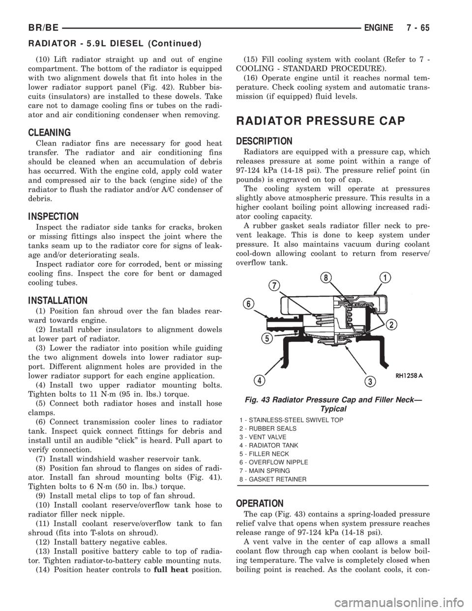
The cap (Fig. 43) contains a spring-loaded pressure
relief valve that opens when system pressure reaches
release range of 97-124 kPa (14-18 psi).
A vent valve in the center of cap allows a small
coolant flow through cap when coolant is below boil-
ing temperature. The valve is completely closed when
boiling point is reached. As the coolant cools, it con-
Fig. 43 Radiator Pressure Cap and Filler NeckÐ
Typical
1 - STAINLESS-STEEL SWIVEL TOP
2 - RUBBER SEALS
3 - VENT VALVE
4 - RADIATOR TANK
5 - FILLER NECK
6 - OVERFLOW NIPPLE
7 - MAIN SPRING
8 - GASKET RETAINER
BR/BEENGINE 7 - 65
RADIATOR - 5.9L DIESEL (Continued)
Page 402 of 2889
ket has swollen and prevents vent valve from open-
ing, replace cap.
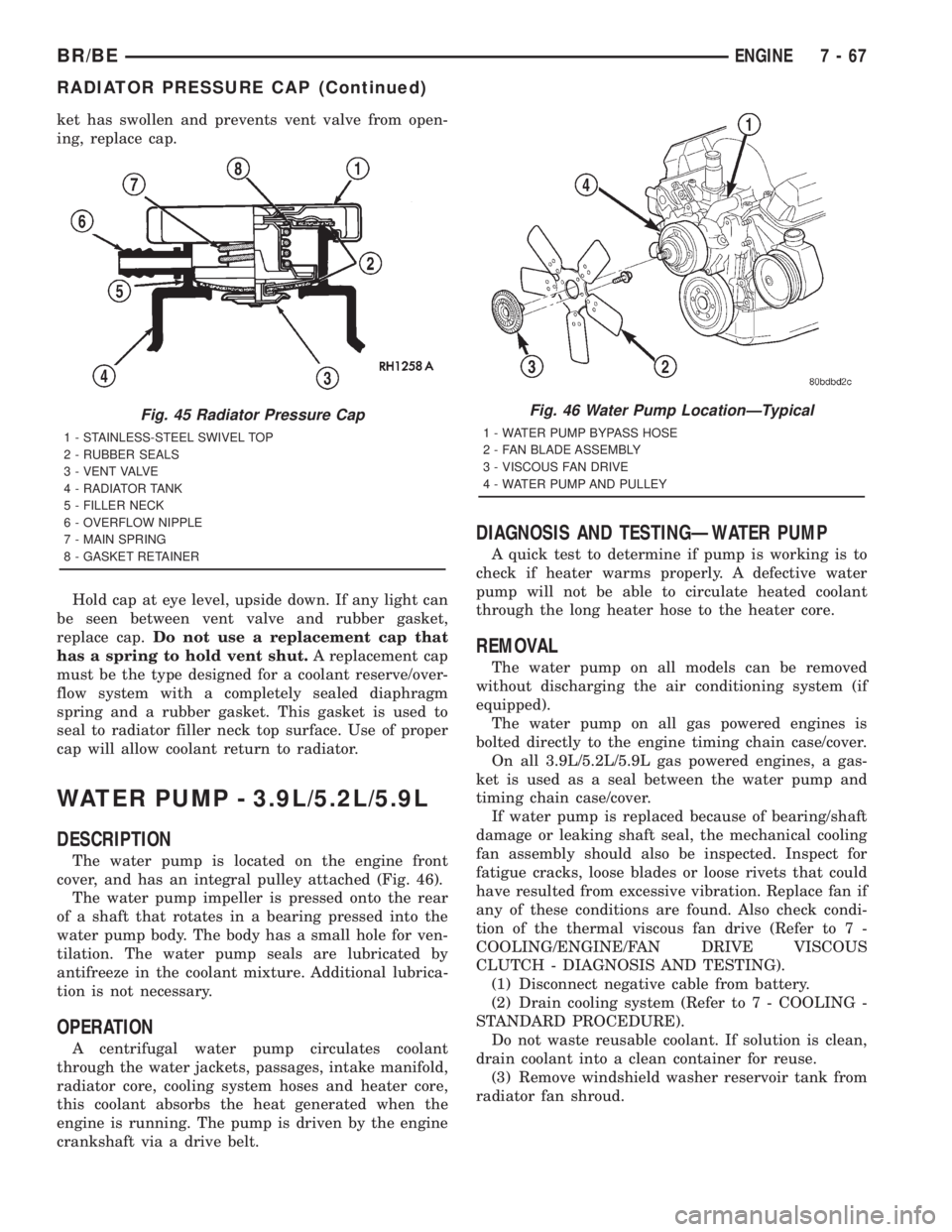
Hold cap at eye level, upside down. If any light can
be seen between vent valve and rubber gasket,
replace cap.Do not use a replacement cap that
has a spring to hold vent shut.A replacement cap
must be the type designed for a coolant reserve/over-
flow system with a completely sealed diaphragm
spring and a rubber gasket. This gasket is used to
seal to radiator filler neck top surface. Use of proper
cap will allow coolant return to radiator.
WATER PUMP - 3.9L/5.2L/5.9L
DESCRIPTION
The water pump is located on the engine front
cover, and has an integral pulley attached (Fig. 46).
The water pump impeller is pressed onto the rear
of a shaft that rotates in a bearing pressed into the
water pump body. The body has a small hole for ven-
tilation. The water pump seals are lubricated by
antifreeze in the coolant mixture. Additional lubrica-
tion is not necessary.
OPERATION
A centrifugal water pump circulates coolant
through the water jackets, passages, intake manifold,
radiator core, cooling system hoses and heater core,
this coolant absorbs the heat generated when the
engine is running. The pump is driven by the engine
crankshaft via a drive belt.
DIAGNOSIS AND TESTINGÐWATER PUMP
A quick test to determine if pump is working is to
check if heater warms properly. A defective water
pump will not be able to circulate heated coolant
through the long heater hose to the heater core.
REMOVAL
The water pump on all models can be removed
without discharging the air conditioning system (if
equipped).
The water pump on all gas powered engines is
bolted directly to the engine timing chain case/cover.
On all 3.9L/5.2L/5.9L gas powered engines, a gas-
ket is used as a seal between the water pump and
timing chain case/cover.
If water pump is replaced because of bearing/shaft
damage or leaking shaft seal, the mechanical cooling
fan assembly should also be inspected. Inspect for
fatigue cracks, loose blades or loose rivets that could
have resulted from excessive vibration. Replace fan if
any of these conditions are found. Also check condi-
tion of the thermal viscous fan drive (Refer to 7 -
COOLING/ENGINE/FAN DRIVE VISCOUS
CLUTCH - DIAGNOSIS AND TESTING).
(1) Disconnect negative cable from battery.
(2) Drain cooling system (Refer to 7 - COOLING -
STANDARD PROCEDURE).
Do not waste reusable coolant. If solution is clean,
drain coolant into a clean container for reuse.
(3) Remove windshield washer reservoir tank from
radiator fan shroud.
Fig. 45 Radiator Pressure Cap
1 - STAINLESS-STEEL SWIVEL TOP
2 - RUBBER SEALS
3 - VENT VALVE
4 - RADIATOR TANK
5 - FILLER NECK
6 - OVERFLOW NIPPLE
7 - MAIN SPRING
8 - GASKET RETAINER
Fig. 46 Water Pump LocationÐTypical
1 - WATER PUMP BYPASS HOSE
2 - FAN BLADE ASSEMBLY
3 - VISCOUS FAN DRIVE
4 - WATER PUMP AND PULLEY
BR/BEENGINE 7 - 67
RADIATOR PRESSURE CAP (Continued)
Page 447 of 2889
²Head/Park Lights-On Warning- The CTM
chime tone generator will generate repetitive chime
tones at a fast rate to announce that hard wired
inputs from the driver door ajar switch, headlamp
switch, and ignition switch indicate that the exterior
lamps are turned On with the driver side front door
opened and the ignition switch in the Off position.
The chimes will continue to sound until the exterior
lamps are turned Off, the driver side front door is
closed, or the ignition switch is turned to the On
position, whichever occurs first.
²Key-In-Ignition Warning- The BCM chime
tone generator will generate repetitive chime tones at
a fast rate to announce that hard wired inputs from
the driver door ajar switch, headlamp switch, and
ignition switch indicate that the key is in the ignition
lock cylinder with the driver side front door opened
and the ignition switch in the Off position. The
chimes will continue to sound until the key is
removed from the ignition lock cylinder, the driver
side front door is closed, or the ignition switch is
turned to the On position, whichever occurs first.
²Warning Chime Support- The CTM chime
tone generator will generate repetitive chime tones at
a slow rate to announce that a hard wired chime
request input has been received from the EMIC.
These chime tones provide an audible alert to the
vehicle operator that supplements certain visual indi-
cations displayed by the EMIC. Supplemented indica-
tions include the following:
²The ªAirbagº indicator is illuminated. The
chimes will continue to sound for a duration of about
four seconds each time the indicator is illuminated or
until the ignition switch is turned to the Off position,
whichever occurs first.
²The ªCheck Gagesº indicator is illuminated. The
chimes will continue to sound for a duration of about
two seconds each time the indicator is illuminated or
until the ignition switch is turned to the Off position,
whichever occurs first.
²The ªLow Fuelº indicator is illuminated. The
chimes will continue to sound for a duration of about
two seconds each time the indicator is illuminated or
until the ignition switch is turned to the Off position,
whichever occurs first.
²The ªLow Washº indicator is illuminated. The
chimes will continue to sound for a duration of about
two seconds each time the indicator is illuminated or
until the ignition switch is turned to the Off position,
whichever occurs first.
²The ªTrans Tempº indicator is illuminated (auto-
matic transmission only). The chimes will continue to
sound for a duration of about two seconds each time
the indicator is illuminated or until the ignition
switch is turned to the Off position, whichever occurs
first.²The vehicle is over a programmed speed value
(Middle East Gulf Coast Country (GCC) only). The
CTM chime tone generator will generate repetitive
chime tones at a slow rate to announce that the vehi-
cle speed exceeds a programmed value. The chimes
will continue to sound until the vehicle speed is
below the programmed value.
²The ªWater-In-Fuelº indicator is illuminated
(diesel engine only). The chimes will continue to
sound for a duration of about two seconds each time
the indicator is illuminated or until the ignition
switch is turned to the Off position, whichever occurs
first.
The CTM provides chime service for all available
features in the chime warning system. The CTM
relies upon hard wired inputs from the driver door
ajar switch, the EMIC, the headlamp switch, and the
key-in ignition switch (ignition switch) to provide
chime service for all of the chime warning system
features. Upon receiving the proper inputs, the CTM
activates the integral chime tone generator to pro-
vide the audible chime tone to the vehicle operator.
The chime tone generator in the CTM is capable of
producing repeated chime tones at two different
rates, slow or fast. The slow chime rate is about fifty
chime tones per minute, while the fast chime rate is
about 180 chime tones per minute. The internal pro-
gramming of the CTM and the EMIC determines the
priority of each chime tone request input that is
received, as well as the rate and duration of each
chime tone that is to be generated.
The hard wired chime warning system inputs to
the CTM and the EMIC, as well as other hard wired
circuits for this system may be diagnosed and tested
using conventional diagnostic tools and procedures.
See the owner's manual in the vehicle glove box for
more information on the features provided by the
chime warning system.
DIAGNOSIS AND TESTING - CHIME WARNING
SYSTEM
Refer to the appropriate wiring information. The
wiring information includes wiring diagrams, proper
wire and connector repair procedures, further details
on wire harness routing and retention, as well as
pin-out and location views for the various wire har-
ness connectors, splices and grounds. The hard wired
chime warning system inputs to the Central Timer
Module (CTM) and the Electro-Mechanical Instru-
ment Cluster (EMIC), as well as other hard wired
circuits for this system may be diagnosed and tested
using conventional diagnostic tools and procedures.
8B - 2 CHIME/BUZZERBR/BE
CHIME WARNING SYSTEM (Continued)
Page 510 of 2889
ENGINE STARTER MOTOR
DESCRIPTION
The starter motors used for the 5.9L diesel engine
and the 8.0L gasoline engine available in this model
are not interchangeable with each other, or with the
starter motors used for the other available engines.
The starter motors used for the 3.9L, 5.2L and the
5.9L gasoline engines available in this model are
interchangeable.
The starter motor for the 5.9L diesel engine is
mounted with three screws to the flywheel housing
on the left side of the engine. The starter motor for
the 8.0L gasoline engine is mounted with two screws
to the flange on the left rear corner of the engine
block, while the starter motors for all of the other
engines are mounted with one screw, a stud and a
nut to the manual transmission clutch housing or
automatic transmission torque converter housing and
are located on the left side of the engine.
Each of these starter motors incorporates several
of the same features to create a reliable, efficient,
compact, lightweight and powerful unit. The electric
motors of all of these starters have four brushes con-
tacting the motor commutator, and feature four elec-
tromagnetic field coils wound around four pole shoes.
The 3.9L, 5.2L, 5.9L and 8.0L gasoline engine starter
motors are rated at 1.4 kilowatts (about 1.9 horse-
power) output at 12 volts, while the 5.9L diesel
engine starter motor is rated at 2.7 kilowatts (about
3.6 horsepower) output at 12 volts.
All of these starter motors are serviced only as a
unit with their starter solenoids, and cannot be
repaired. If either component is faulty or damaged,
the entire starter motor and starter solenoid unit
must be replaced.
OPERATION
These starter motors are equipped with a gear
reduction (intermediate transmission) system. The
gear reduction system consists of a gear that is inte-
gral to the output end of the electric motor armature
shaft that is in continual engagement with a larger
gear that is splined to the input end of the starter
pinion gear shaft. This feature makes it possible to
reduce the dimensions of the starter. At the same
time, it allows higher armature rotational speed and
delivers increased torque through the starter pinion
gear to the starter ring gear.
The starter motors for all engines are activated by
an integral heavy duty starter solenoid switch
mounted to the overrunning clutch housing. This
electromechanical switch connects and disconnects
the feed of battery voltage to the starter motor, also
engaging and disengaging the starter pinion gear
with the starter ring gear.All starter motors use an overrunning clutch and
starter pinion gear unit to engage and drive a starter
ring gear that is integral to the flywheel (manual
transmission), torque converter or torque converter
drive plate (automatic transmission) mounted on the
rear crankshaft flange.
DIAGNOSIS AND TESTING - STARTER MOTOR
Correct starter motor operation can be confirmed
by performing the following free running bench test.
This test can only be performed with starter motor
removed from vehicle. Refer to Starter Specifications
for starter motor specifications.
(1) Remove starter motor from vehicle. Refer to
Starter MotorRemoval and Installation.
(2) Mount starter motor securely in a soft-jawed
bench vise. The vise jaws should be clamped on
mounting flange of starter motor. Never clamp on
starter motor by field frame.
(3) Connect suitable volt-ampere tester and 12-volt
battery to starter motor in series, and set ammeter to
100 ampere scale (250 ampere scale for diesel engine
starters). See instructions provided by manufacturer
of volt-ampere tester being used.
(4) Install jumper wire from solenoid terminal to
solenoid battery terminal. The starter motor should
operate. If starter motor fails to operate, replace
faulty starter motor assembly.
(5) Adjust carbon pile load of tester to obtain free
running test voltage. Refer to Specifications for the
starter motor free running test voltage specifications.
(6) Note reading on ammeter and compare this
reading to free running test maximum amperage
draw. Refer to Specifications for starter motor free
running test maximum amperage draw specifica-
tions.
(7) If ammeter reading exceeds maximum amper-
age draw specification, replace faulty starter motor
assembly.
STARTER MOTOR SOLENOID
This test can only be performed with starter motor
removed from vehicle.
(1) Remove starter motor. Refer toStarter Motor
Removal and Installation.
(2) Disconnect wire from solenoid field coil termi-
nal.
(3) Check for continuity between solenoid terminal
and solenoid field coil terminal with continuity tester
(Fig. 7). There should be continuity. If OK, go to Step
4. If not OK, replace faulty starter motor assembly.
(4) Check for continuity between solenoid terminal
and solenoid case (Fig. 8). There should be continuity.
If not OK, replace faulty starter motor assembly.
BR/BESTARTING 8F - 39
Page 521 of 2889

OPERATION
The heated seat module receives fused battery cur-
rent through the energized heated seat relay in the
Junction Block (JB) only when the engine is running.
The heated seat switches receive battery current
through a fused ignition switch output (run) circuit
only when the ignition switch is in the On position.
The heated seat module shares a common ground cir-
cuit with each of the heated seat elements. The
heated seat elements will only operate when the sur-
face temperature of the seat cushion cover at the
heated seat sensors is below the designed tempera-
ture set points of the system.
The heated seat module will automatically turn off
the heated seat elements if it detects a short in the
heated seat element circuit or a heated seat sensor
value that is out of range. The heated seat system
will also be turned off automatically whenever the
ignition switch is turned to any position except On or
if the engine quits running. If the ignition switch is
turned to the Off position or if the engine quits run-
ning while a heated seat is turned ON, the heated
seat will remain Off after the engine is restarted
until a heated seat switch is depressed again.
The heated seat module monitors inputs from the
heated seat sensors and the heated seat switches. In
response to these inputs the heated seat module uses
its internal programming to control outputs to the
heated seat elements in both front seats and to con-
trol the heated seat LED indicator lamps located in
both of the heated seat switches. The heated seat
module is also programmed to provide a self-diagnos-
tic capability. When the module detects certain fail-
ures within the heated seat system, it will provide a
visual indication of the failure by flashing the indica-
tor lamps in the heated seat switches.
DIAGNOSIS & TESTING - HEATED SEAT
SYSTEM
SELF-DIAGNOSIS
The heated seat system is capable of performing
some self-diagnostics. The following table depicts the
various failure modes which will be reported to the
vehicle operator or technician by flashing the individ-
ual heated seat switch Light Emitting Diode (LED)
indicator lamps. See the Heated Seat System Self-Di-
agnosis table for the diagnostic routines. The driver
side heated seat switch indicator lamps will flash if a
failure occurs in the driver side heated seat, and the
passenger side heated seat switch indicator lamps
will flash for a passenger side heated seat failure. If
a monitored heated seat system failure occurs, the
switch indicator lamps will flash at a pulse rate of
about one-half second on, followed by about one-half
second off for a duration of about one minute afterthe switch for the faulty heated seat is depressed in
either the Low or High direction. This process will
repeat every time the faulty heated seat switch is
actuated until the problem has been corrected.
Heated Seat System Self-Diagnosis
Monitored FailureSwitch High
Indicator LampSwitch Low
Indicator Lamp
Heated Seat
Element ShortedFlashing Flashing
Heated Seat
Element OpenFlashing Off
Heated Seat
Sensor Value Out
of RangeOff Flashing
TESTING
Refer toPower Seatin the index of this service
manual for the location of complete heated seat sys-
tem wiring diagrams. Before testing the individual
components in the heated seat system, perform the
following preliminary checks:
WARNING: ON VEHICLES EQUIPPED WITH AIR-
BAGS, DISABLE THE AIRBAG SYSTEM BEFORE
ATTEMPTING ANY STEERING WHEEL, STEERING
COLUMN, OR INSTRUMENT PANEL COMPONENT
DIAGNOSIS OR SERVICE. DISCONNECT AND ISO-
LATE THE BATTERY NEGATIVE (GROUND) CABLE,
THEN WAIT TWO MINUTES FOR THE AIRBAG SYS-
TEM CAPACITOR TO DISCHARGE BEFORE PER-
FORMING FURTHER DIAGNOSIS OR SERVICE. THIS
IS THE ONLY SURE WAY TO DISABLE THE AIRBAG
SYSTEM. FAILURE TO TAKE THE PROPER PRE-
CAUTIONS COULD RESULT IN ACCIDENTAL AIR-
BAG DEPLOYMENT AND POSSIBLE PERSONAL
INJURY.
²If the heated seat switch back lighting and the
cluster illumination lamps do not illuminate with the
headlamps or park lamps turned On, refer toInstru-
ment Clusterin the index of this service manual for
the location of the proper cluster illumination lamps
diagnosis and testing procedures. If the heated seat
switch back lighting does not illuminate, but the
cluster illumination lamps do illuminate with the
headlamps or park lamps turned On, refer to
Heated Seat Switchin this section for the location
of the proper heated seat switch diagnosis and test-
ing procedure.
²If a single indicator lamp for one heated seat
switch does not operate and the heated seat elements
do heat, refer toHeated Seat Switchin this section
for the location of the proper heated seat switch diag-
nosis and testing procedure.
8G - 6 HEATED SEAT SYSTEMBR/BE
HEATED SEAT SYSTEM (Continued)
Page 549 of 2889

removed). Then continue to slowly rotate engine
clockwise until indicating mark (Fig. 18) is aligned to
0 degree (TDC) mark on timing chain cover.
(1) Clean top of cylinder block for a good seal
between distributor base and block.
(2) Lightly oil the rubber o-ring seal on the distrib-
utor housing.
(3) Install rotor to distributor shaft.
(4) Position distributor into engine to its original
position. Engage tongue of distributor shaft with slot
in distributor oil pump drive gear. Position rotor to
the number one spark plug cable position.
(5) Install distributor holddown clamp and clamp
bolt. Do not tighten bolt at this time.(6) Rotate the distributor housing until rotor is
aligned to CYL. NO. 1 alignment mark on the cam-
shaft position sensor (Fig. 19) .
(7) Tighten clamp holddown bolt (Fig. 20) to 22.5
N´m (200 in. lbs.) torque.
(8) Connect camshaft position sensor wiring har-
ness to main engine harness.
(9) Install distributor cap. Tighten mounting
screws.
(10) Refer to the following, Checking Distributor
Position.
Checking Distributor Position
To verify correct distributor rotational position, the
DRB scan tool must be used.
WARNING: WHEN PERFORMING THE FOLLOWING
TEST, THE ENGINE WILL BE RUNNING. BE CARE-
FUL NOT TO STAND IN LINE WITH THE FAN
BLADES OR FAN BELT. DO NOT WEAR LOOSE
CLOTHING.
(1) Connect DRB scan tool to data link connector.
The data link connector is located in passenger com-
partment, below and to left of steering column.
(2) Gain access to SET SYNC screen on DRB.
(3) Follow directions on DRB screen and start
engine. Bring to operating temperature (engine must
be in ªclosed loopº mode).
(4) With engine running atidle speed, the words
IN RANGE should appear on screen along with 0É.
This indicates correct distributor position.
(5) If a plus (+) or a minus (-) is displayed next to
degree number, and/or the degree displayed is not
zero, loosen but do not remove distributor holddown
clamp bolt. Rotate distributor until IN RANGE
appears on screen. Continue to rotate distributor
until achieving as close to 0É as possible. After
adjustment, tighten clamp bolt to 22.5 N´m (200 in.
lbs.) torque.
The degree scale on SET SYNC screen of DRB is
referring to fuel synchronization only.It is not
referring to ignition timing.Because of this, do
not attempt to adjust ignition timing using this
method. Rotating distributor will have no effect on
ignition timing. All ignition timing values are con-
trolled by powertrain control module (PCM).
After testing, install air cleaner assembly.
DISTRIBUTOR CAP
DIAGNOSIS AND TESTING - DISTRIBUTOR
CAP
Remove the distributor cap and wipe it clean with
a dry lint free cloth. Visually inspect the cap for
cracks, carbon paths, broken towers or damaged
Fig. 19 Rotor Alignment Mark
1 - CAMSHAFT POSITION SENSOR ALIGNMENT MARK
2 - ROTOR
3 - DISTRIBUTOR
Fig. 20 Distributor Holddown Clamp
1 - CLAMP BOLT
2 - HOLDDOWN CLAMP
3 - DISTRIBUTOR HOUSING
8I - 12 IGNITION CONTROLBR/BE
DISTRIBUTOR (Continued)
Page 553 of 2889
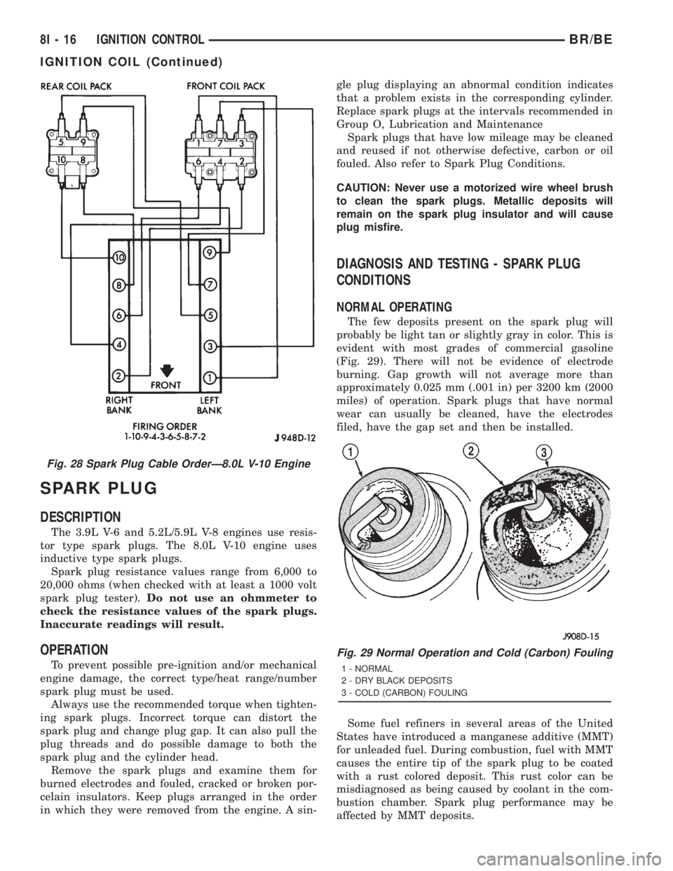
SPARK PLUG
DESCRIPTION
The 3.9L V-6 and 5.2L/5.9L V-8 engines use resis-
tor type spark plugs. The 8.0L V-10 engine uses
inductive type spark plugs.
Spark plug resistance values range from 6,000 to
20,000 ohms (when checked with at least a 1000 volt
spark plug tester).Do not use an ohmmeter to
check the resistance values of the spark plugs.
Inaccurate readings will result.
OPERATION
To prevent possible pre-ignition and/or mechanical
engine damage, the correct type/heat range/number
spark plug must be used.
Always use the recommended torque when tighten-
ing spark plugs. Incorrect torque can distort the
spark plug and change plug gap. It can also pull the
plug threads and do possible damage to both the
spark plug and the cylinder head.
Remove the spark plugs and examine them for
burned electrodes and fouled, cracked or broken por-
celain insulators. Keep plugs arranged in the order
in which they were removed from the engine. A sin-gle plug displaying an abnormal condition indicates
that a problem exists in the corresponding cylinder.
Replace spark plugs at the intervals recommended in
Group O, Lubrication and Maintenance
Spark plugs that have low mileage may be cleaned
and reused if not otherwise defective, carbon or oil
fouled. Also refer to Spark Plug Conditions.
CAUTION: Never use a motorized wire wheel brush
to clean the spark plugs. Metallic deposits will
remain on the spark plug insulator and will cause
plug misfire.
DIAGNOSIS AND TESTING - SPARK PLUG
CONDITIONS
NORMAL OPERATING
The few deposits present on the spark plug will
probably be light tan or slightly gray in color. This is
evident with most grades of commercial gasoline
(Fig. 29). There will not be evidence of electrode
burning. Gap growth will not average more than
approximately 0.025 mm (.001 in) per 3200 km (2000
miles) of operation. Spark plugs that have normal
wear can usually be cleaned, have the electrodes
filed, have the gap set and then be installed.
Some fuel refiners in several areas of the United
States have introduced a manganese additive (MMT)
for unleaded fuel. During combustion, fuel with MMT
causes the entire tip of the spark plug to be coated
with a rust colored deposit. This rust color can be
misdiagnosed as being caused by coolant in the com-
bustion chamber. Spark plug performance may be
affected by MMT deposits.
Fig. 28 Spark Plug Cable OrderÐ8.0L V-10 Engine
Fig. 29 Normal Operation and Cold (Carbon) Fouling
1 - NORMAL
2 - DRY BLACK DEPOSITS
3 - COLD (CARBON) FOULING
8I - 16 IGNITION CONTROLBR/BE
IGNITION COIL (Continued)
Page 557 of 2889
With the engine running, remove spark plug cable
from spark plug (one at a time) and hold next to a
good engine ground. If the cable and spark plug are
in good condition, the engine rpm should drop and
the engine will run poorly. If engine rpm does not
drop, the cable and/or spark plug may not be operat-
ing properly and should be replaced. Also check
engine cylinder compression.
With the engine not running, connect one end of a
test probe to a good ground. Start the engine and run
the other end of the test probe along the entire
length of all spark plug cables. If cables are cracked
or punctured, there will be a noticeable spark jump
from the damaged area to the test probe. The cable
running from the ignition coil to the distributor cap
can be checked in the same manner. Cracked, dam-
aged or faulty cables should be replaced with resis-
tance type cable. This can be identified by the words
ELECTRONIC SUPPRESSION printed on the cable
jacket.
Use an ohmmeter to test for open circuits, exces-
sive resistance or loose terminals. If equipped,
remove the distributor cap from the distributor.Do
not remove cables from cap.Remove cable from
spark plug. Connect ohmmeter to spark plug termi-
nal end of cable and to corresponding electrode in
distributor cap. Resistance should be 250 to 1000
Ohms per inch of cable. If not, remove cable from dis-
tributor cap tower and connect ohmmeter to the ter-
minal ends of cable. If resistance is not within
specifications as found in the SPARK PLUG CABLE
RESISTANCE chart, replace the cable. Test all spark
plug cables in this manner.
SPARK PLUG CABLE RESISTANCE
MINIMUM MAXIMUM
250 Ohms Per Inch 1000 Ohms Per Inch
3000 Ohms Per Foot 12,000 Ohms Per Foot
To test ignition coil-to-distributor cap cable, do not
remove the cable from the cap. Connect ohmmeter to
rotor button (center contact) of distributor cap and
terminal at ignition coil end of cable. If resistance is
not within specifications as found in the Spark Plug
Cable Resistance chart, remove the cable from the
distributor cap. Connect the ohmmeter to the termi-
nal ends of the cable. If resistance is not within spec-
ifications as found in the Spark Plug Cable
Resistance chart, replace the cable. Inspect the igni-
tion coil tower for cracks, burns or corrosion.
REMOVAL
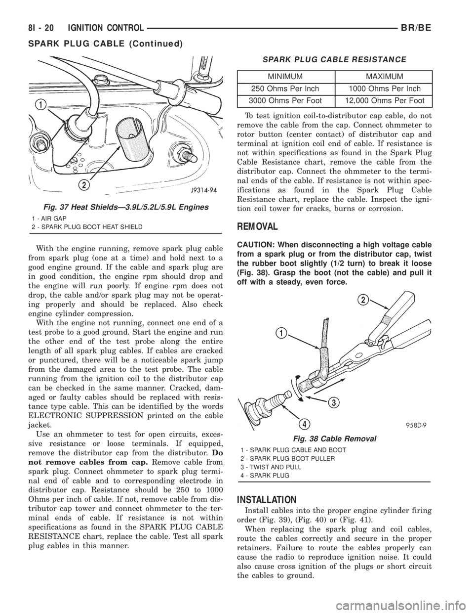
CAUTION: When disconnecting a high voltage cable
from a spark plug or from the distributor cap, twist
the rubber boot slightly (1/2 turn) to break it loose
(Fig. 38). Grasp the boot (not the cable) and pull it
off with a steady, even force.
INSTALLATION
Install cables into the proper engine cylinder firing
order (Fig. 39), (Fig. 40) or (Fig. 41).
When replacing the spark plug and coil cables,
route the cables correctly and secure in the proper
retainers. Failure to route the cables properly can
cause the radio to reproduce ignition noise. It could
also cause cross ignition of the plugs or short circuit
the cables to ground.
Fig. 37 Heat ShieldsÐ3.9L/5.2L/5.9L Engines
1 - AIR GAP
2 - SPARK PLUG BOOT HEAT SHIELD
Fig. 38 Cable Removal
1 - SPARK PLUG CABLE AND BOOT
2 - SPARK PLUG BOOT PULLER
3 - TWIST AND PULL
4 - SPARK PLUG
8I - 20 IGNITION CONTROLBR/BE
SPARK PLUG CABLE (Continued)